
In modern heavy-duty machinery, such as naval propulsion systems, the demand for high-power, high-speed transmission has led to the widespread adoption of herringbone gears. These gears are renowned for their exceptional load-carrying capacity, smooth operation, and ability to cancel axial forces. However, under severe operating conditions, herringbone gears can experience significant dynamic issues, including vibration and noise, which compromise system reliability and performance. As a result, there is a pressing need to develop effective vibration control strategies, with tooth surface modification emerging as a key technique. To validate the efficacy of such modifications, accurate vibration testing is essential. Open-loop test benches, while direct, are often energy-intensive and costly. In contrast, closed power flow test benches offer a sustainable alternative by recirculating energy within the system, enabling stable loading and reduced power consumption. In this article, I will explore the feasibility of using a closed power flow test bench for vibration testing of herringbone gears with tooth surface modification. Through detailed modeling and analysis, I aim to demonstrate that the influence of accompanying gears on the test results is minimal, making this approach practical for evaluating vibration reduction in modified herringbone gears.
Herringbone gears, characterized by their double-helical structure, are integral to many industrial applications due to their superior performance. The unique geometry allows for balanced axial forces, reducing bearing loads and enhancing durability. However, the dynamic behavior of herringbone gears is complex, involving coupling between bending, torsion, and axial vibrations. Tooth surface modification, such as tip and root relief or lead crowning, is commonly employed to mitigate meshing impacts, lower noise, and improve load distribution. Validating these modifications requires precise measurement of relative vibration acceleration along the meshing line. Traditional vibration testing methods often rely on open-loop setups, which are resource-intensive. The closed power flow test bench, by contrast, creates a self-contained energy loop, where power is circulated between driving and loading units, minimizing external energy input. This design not only conserves energy but also provides consistent loading conditions, which is crucial for repeatable vibration measurements. In this context, I have developed a specialized test bench for herringbone gears, focusing on assessing the impact of tooth surface modifications on dynamic response.
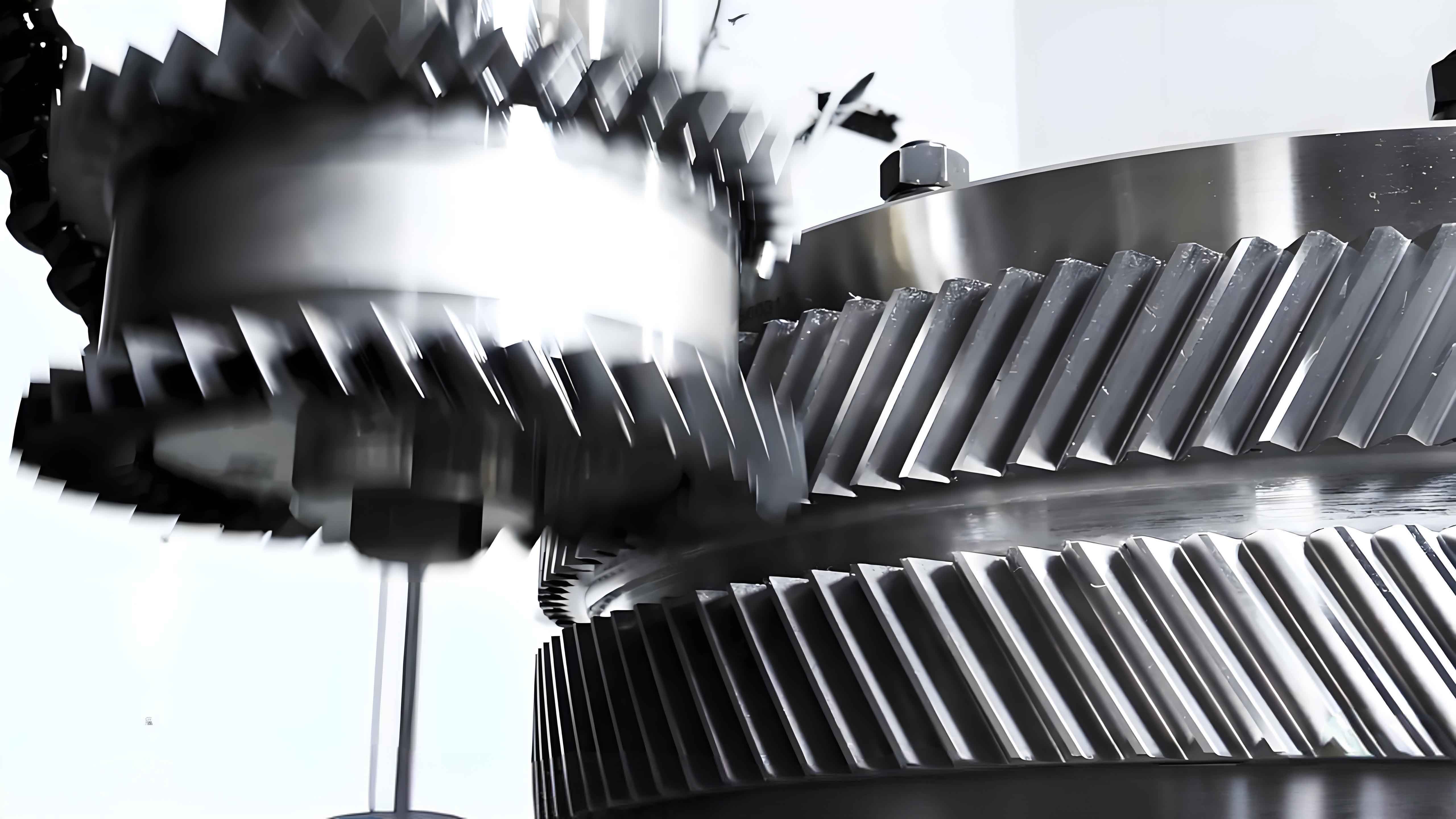
The closed power flow test bench for herringbone gears consists of two main sections: the test gearbox and the accompanying gearbox. These are connected via torsion shafts that facilitate power circulation and loading. A schematic of the power flow is shown, illustrating how torque is applied through a loading mechanism on the torsion shaft. When the system operates under steady conditions, the power flows in a closed loop, typically from the driving motor through the test herringbone gears, then to the accompanying herringbone gears, and back. This setup allows for controlled vibration testing under various loads and speeds. For instance, in our configuration, the test herringbone gears act as a reduction stage, with the accompanying gears providing the necessary reaction torque. The key components include herringbone gear pairs, support bearings, torsion shafts with adjustable stiffness, and sensors such as rotary encoders to measure angular displacement and compute relative vibration acceleration. The design prioritizes minimizing external influences, but the presence of accompanying gears inevitably introduces some coupling effects on the test gear vibration. Therefore, it is critical to quantify this influence to ensure the validity of test results, especially when evaluating subtle effects like tooth surface modification.
To analyze the dynamic behavior, I established a comprehensive vibration model for the herringbone gear system within the closed power flow test bench. This model accounts for the test herringbone gears, accompanying herringbone gears, and the torsion shafts, resulting in a 24-degree-of-freedom (DOF) coupled bending-torsion-axial vibration system. Each herringbone gear pair is modeled considering left and right helical segments, with coupling through the gear body. The equations of motion are derived based on Newton’s second law, incorporating meshing forces, support stiffness, and damping. For a single herringbone gear pair, the dynamic meshing forces along the line of action and axial direction are expressed as functions of relative displacement and time-varying mesh stiffness. The overall system model integrates multiple gear pairs connected by torsion shafts, whose stiffness and damping parameters significantly affect the dynamic response. The governing equations for the test and accompanying gears can be summarized in a matrix form, but for clarity, I present key equations below.
The dynamic meshing force for a herringbone gear pair along the line of action is given by:
$$F_{y}(t) = k_m(t) \cdot \delta_y(t) + c_m \cdot \dot{\delta}_y(t)$$
where \( k_m(t) \) is the time-varying mesh stiffness, \( c_m \) is the meshing damping coefficient, and \( \delta_y(t) \) is the relative displacement along the meshing line. For herringbone gears, the mesh stiffness varies with tooth engagement and modification profiles. Similarly, the axial force component is:
$$F_{z}(t) = k_a \cdot \delta_z(t) + c_a \cdot \dot{\delta}_z(t)$$
where \( k_a \) and \( c_a \) represent axial stiffness and damping, respectively. The equations of motion for a gear body in the system include translational and rotational DOFs. For instance, for the test pinion (left segment), the equations are:
$$m_{p1} \ddot{y}_{p1} + c_{p1y} \dot{y}_{p1} + k_{p1y} y_{p1} = -F_{y1}$$
$$m_{p1} \ddot{z}_{p1} + c_{p12z} (\dot{z}_{p1} – \dot{z}_{p2}) + k_{p12z} (z_{p1} – z_{p2}) = -F_{z1}$$
$$I_{p1} \ddot{\theta}_{p1} = -F_{y1} R_p + T_{p1} – F_{s1} R_p – k_{TSH} (\theta_{p1} – \theta_{p2}) – c_{TSH} (\dot{\theta}_{p1} – \dot{\theta}_{p2})$$
Here, \( m_{p1} \), \( I_{p1} \), \( y_{p1} \), \( z_{p1} \), and \( \theta_{p1} \) are mass, moment of inertia, translational displacements, and rotational displacement of the pinion. \( R_p \) is the pitch radius, \( T_{p1} \) is external torque, \( F_{s1} \) is shock force, and \( k_{TSH} \), \( c_{TSH} \) are torsion shaft stiffness and damping. Similar equations apply to other gears, forming a system of 24 equations. The parameters for the test bench and herringbone gears are summarized in Table 1.
| Parameter | Pinion | Gear |
|---|---|---|
| Load Torque (N·m) | — | 828 |
| Input Speed (r/min) | 2000 | — |
| Torsion Shaft Length (mm) | 800 | 1000 |
| Torsion Shaft Diameter (mm) | 21 | 29 |
| Normal Module (mm) | 6 | 6 |
| Pressure Angle (degrees) | 20 | 20 |
| Helix Angle (degrees) | 24.43 | -24.43 |
| Number of Teeth | 17 | 44 |
| Face Width (mm) | 55 | 55 |
| Relief Groove Width (mm) | 58 | 58 |
| Mean Mesh Stiffness (N/m) | 2.3 × 10⁹ | 2.3 × 10⁹ |
| Mesh Damping Coefficient | 0.1 | 0.1 |
The time-varying mesh stiffness for herringbone gears is computed using load tooth contact analysis (LTCA), which accounts for tooth flexibility and contact patterns. For modified herringbone gears, the stiffness profile changes due to altered tooth geometry. In our case, a three-dimensional tooth surface modification is applied, involving tip relief, root relief, and lead crowning. The modification amounts vary along the tooth profile and face width, as described by parametric curves. This modification aims to reduce vibration by smoothing the meshing process. To evaluate its effectiveness, I performed numerical simulations using the 24-DOF model. First, I analyzed a single herringbone gear pair without accompanying gears to establish a baseline. The relative vibration acceleration along the meshing line was computed for both standard and modified herringbone gears. The results showed a significant reduction in vibration for the modified case, with a calculated damping rate of 18.2%. This demonstrates the potential of tooth surface modification for vibration control in herringbone gears.
Next, I incorporated the accompanying gears and torsion shafts into the model to assess their influence on the test herringbone gears. The accompanying gears are standard involute herringbone gears, while the test gears are modified. The torsion shaft stiffness values are designed based on power transmission requirements, with a typical ratio of \( k_{TSH} / k_{TSL} = (1/i)^{4/3} \), where \( i \) is the gear ratio. In our test bench, the torsion shafts are made of spring steel 60SiMn, with calculated stiffness values of \( 1.78 \times 10^3 \, \text{N·m/rad} \) for the high-speed shaft and \( 8.09 \times 10^3 \, \text{N·m/rad} \) for the low-speed shaft. The system equations were solved numerically using time-domain integration methods, considering operational conditions such as 2000 r/min input speed and 828 N·m load torque. The relative vibration acceleration of the test herringbone gears was computed under different torsion shaft stiffness scenarios to isolate the effect of accompanying gears.
The results indicate that the presence of accompanying gears does affect the vibration measurements, but the extent is minimal. For instance, when the torsion shaft stiffness varies from \( 1 \times 10^3 \, \text{N·m/rad} \) to \( 8 \times 10^3 \, \text{N·m/rad} \), the influence of accompanying gears on the test herringbone gears’ vibration acceleration increases from 1.12% to 3.02%. This is quantified as the percentage deviation in vibration amplitude compared to the single gear pair model. At the actual design stiffness, the maximum influence is only 1.35%, which is substantially lower than the 18.2% vibration reduction achieved through tooth surface modification. Therefore, the closed power flow test bench is feasible for vibration testing of modified herringbone gears, as the accompanying gear effect is negligible relative to the modification impact. To further illustrate, Table 2 summarizes the vibration acceleration values under different conditions.
| Condition | Vibration Acceleration (m/s²) | Influence from Accompanying Gears |
|---|---|---|
| Single Pair, Standard Teeth | 12.45 | — |
| Single Pair, Modified Teeth | 10.18 | — |
| Closed Loop, Modified Teeth (Low Stiffness) | 10.30 | 1.12% |
| Closed Loop, Modified Teeth (High Stiffness) | 10.50 | 3.02% |
| Closed Loop, Modified Teeth (Design Stiffness) | 10.32 | 1.35% |
The relationship between torsion shaft stiffness and the influence of accompanying gears can be expressed mathematically. Assuming linear behavior, the coupled vibration response \( X \) of the test herringbone gears can be modeled as:
$$X = X_0 + \Delta X(k_{TS})$$
where \( X_0 \) is the response without accompanying gears, and \( \Delta X \) is the perturbation due to coupling, which increases with torsion shaft stiffness \( k_{TS} \). From our analysis, \( \Delta X \) is proportional to \( k_{TS} \) within the range considered, as shown in the following approximate relation:
$$\Delta X \approx \alpha \cdot k_{TS}$$
with \( \alpha \) being a constant derived from system parameters. This underscores the importance of designing torsion shafts with low stiffness to minimize coupling effects. In practice, the stiffness should be as low as possible while meeting strength, transmission stability, and layout constraints. For herringbone gear test benches, this design consideration is crucial to ensure accurate vibration measurements.
Beyond stiffness, other factors such as damping in the torsion shafts and support bearings also play a role in the dynamic response. The damping coefficients are typically estimated based on material properties and experimental data. In our model, we used values consistent with industrial practices for herringbone gears. Additionally, the meshing damping coefficient is set to 0.1, which accounts for energy dissipation at the tooth contact. The overall system damping helps attenuate vibrations, but it does not significantly alter the relative influence of accompanying gears. To further validate the model, I conducted sensitivity analyses on key parameters, including mesh stiffness variation, load torque, and rotational speed. The results confirm that the conclusions hold across a range of operating conditions, reinforcing the feasibility of the test bench for herringbone gears.
In terms of practical implementation, the test bench includes instrumentation for measuring vibration. Rotary encoders are attached to the gear shafts to capture angular displacements, which are then processed to compute relative vibration acceleration along the meshing line. The formula for relative vibration acceleration \( a(t) \) is derived from the angular positions \( \theta_p(t) \) and \( \theta_g(t) \) of the pinion and gear:
$$a(t) = R_p \ddot{\theta}_p(t) – R_g \ddot{\theta}_g(t)$$
where \( R_p \) and \( R_g \) are pitch radii. This acceleration is a direct indicator of meshing dynamics and is used to assess vibration reduction from tooth surface modification. The closed power flow design ensures stable loading, which is essential for repeatable measurements. Moreover, the test bench allows for easy swapping of herringbone gear sets, enabling comparative studies between standard and modified designs. This flexibility is valuable for research and development in gear technology.
The advantages of using herringbone gears in heavy-duty applications are well-documented, but their dynamic behavior requires careful analysis. Tooth surface modification is a proven method to enhance performance, but its validation demands precise testing. The closed power flow test bench offers a cost-effective and energy-efficient solution. Our work demonstrates that the influence of accompanying gears is minimal, making it a reliable tool for vibration testing. Future improvements could involve integrating real-time monitoring systems or exploring advanced modification profiles for herringbone gears. Additionally, the model can be extended to include nonlinear effects such as backlash or friction, which may further refine the accuracy of predictions.
In conclusion, the closed power flow test bench for herringbone gears with tooth surface modification is feasible for vibration testing. Through a detailed 24-DOF vibration model, I have shown that the influence of accompanying gears on test results is less than 1.35% under design conditions, which is negligible compared to the 18.2% vibration reduction achieved by modification. The torsion shaft stiffness should be minimized to further reduce coupling effects. This test bench provides a practical and sustainable approach for evaluating the dynamic performance of herringbone gears, contributing to the advancement of gear transmission technology. The insights gained from this study can guide the design of future test setups and help optimize herringbone gear systems for reduced vibration and noise.
To summarize the key equations and parameters, I present the following formulas that encapsulate the dynamic behavior of herringbone gears in the test bench. The overall system equation in matrix form is:
$$M \ddot{X} + C \dot{X} + K X = F(t)$$
where \( M \), \( C \), and \( K \) are mass, damping, and stiffness matrices, respectively, for the 24-DOF system. \( X \) is the displacement vector, and \( F(t) \) is the excitation force vector including meshing and external loads. For herringbone gears, the stiffness matrix \( K \) includes time-varying components due to mesh stiffness variation. The solution of this equation provides the vibration response used in our analysis. The feasibility of the test bench is thus underpinned by rigorous modeling and validation, ensuring that herringbone gears can be effectively tested for vibration characteristics in a closed power flow configuration.
Throughout this article, I have emphasized the importance of herringbone gears in modern machinery and the role of vibration testing in optimizing their design. The closed power flow test bench, with its energy-efficient design, represents a significant step forward in gear testing methodology. By quantifying and minimizing the influence of accompanying gears, we can confidently use this setup to evaluate tooth surface modifications and other vibration control strategies for herringbone gears. This work contributes to the broader goal of enhancing the reliability and performance of gear transmission systems in demanding applications.