
In the field of mechanical transmission design, achieving high power density, lightweight structures, and low noise has always been a primary goal. Spiral bevel gears are widely recognized for their advantages, including high overlap ratio, strength, and quiet operation, making them suitable for applications in aerospace, automotive, and industrial machinery. However, traditional spiral bevel gears typically involve crossed-axis configurations, which can limit space efficiency. On the other hand, planetary gear systems offer benefits such as large transmission ratios, high load capacity, and coaxial input-output alignment. To combine these strengths, I have explored a novel transmission mechanism: the spiral bevel gear planetary system. This design integrates the merits of both spiral bevel gears and planetary gear trains, resulting in a compact and high-performance arrangement. In this article, I will delve into the working principles of this spiral bevel gear planetary mechanism, derive formulas for calculating transmission ratios and efficiency, present experimental results, and discuss its potential applications. Throughout, I will emphasize the role of spiral bevel gears in enhancing transmission performance.
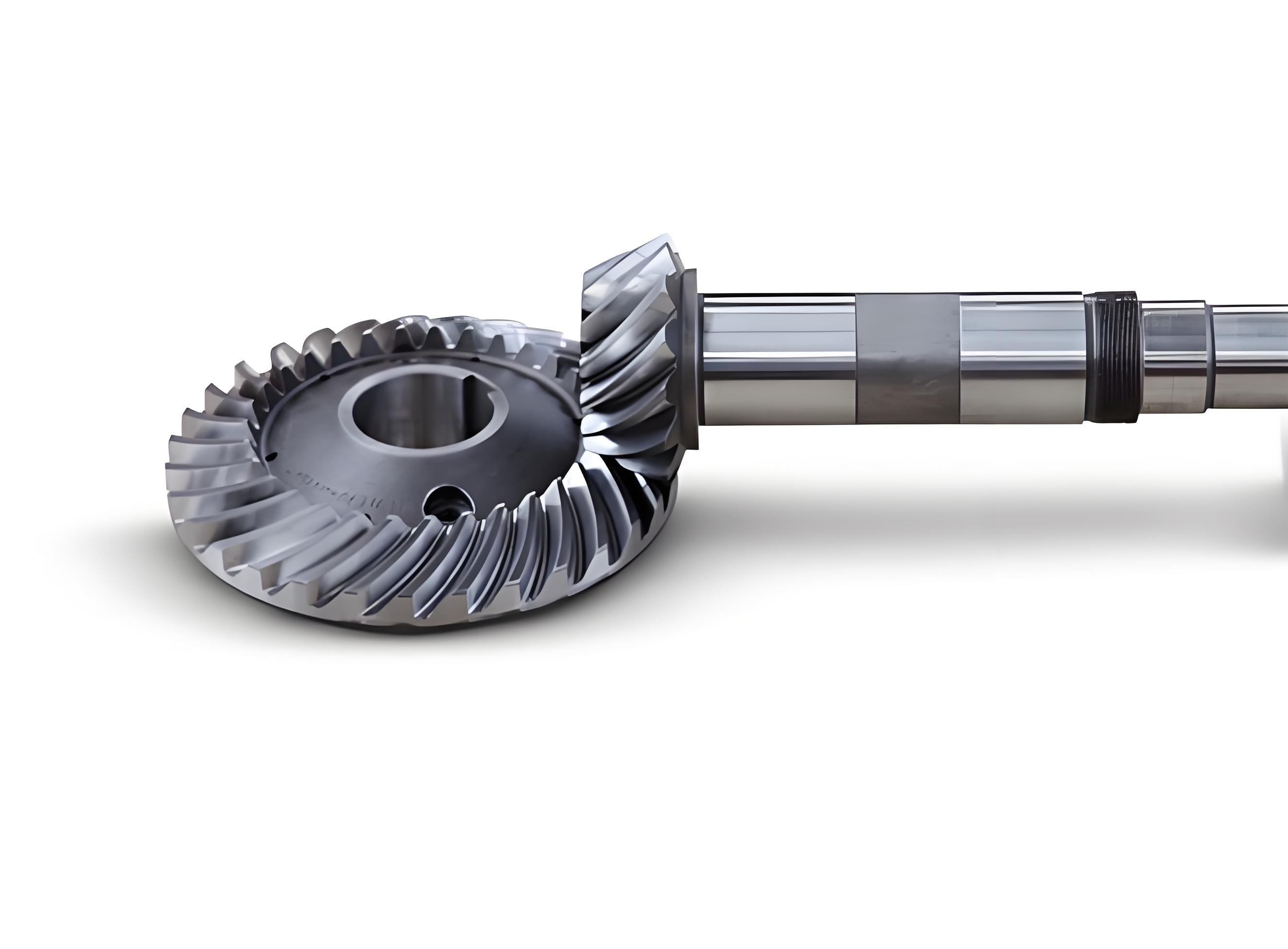
The core idea behind the spiral bevel gear planetary system is to leverage the speed differential between two pairs of externally meshing spiral bevel gears to achieve coaxial transmission, a concept that challenges conventional views on spiral bevel gear applications. Traditionally, spiral bevel gears are used for intersecting shafts, but by arranging them in a planetary configuration, we can enable parallel or coaxial shaft arrangements. The mechanism consists of four spiral bevel gears: two central gears (often referred to as sun gears or fixed gears) and two planetary gears mounted on a common carrier. Specifically, the planetary carrier, denoted as H, holds the planetary gears on a shaft that rotates relative to the central gears. This setup resembles a planetary gear train but uses spiral bevel gears instead of cylindrical gears, offering improved meshing characteristics due to the curved teeth of spiral bevel gears. The inclusion of spiral bevel gears allows for smoother torque transmission and higher load distribution, which is critical in heavy-duty applications.
To understand the transmission principle, consider a basic schematic where gears 1 and 4 are the central spiral bevel gears, and gears 2 and 3 are the planetary spiral bevel gears. The planetary carrier H connects the planetary gears, and the shaft angle Σ defines the orientation. In operation, if one central gear is fixed (e.g., gear 1 attached to the housing), and the other central gear (gear 4) serves as the input or output, the planetary carrier H can act as the output or input, respectively. This configuration enables speed reduction or increase based on gear tooth counts. The use of spiral bevel gears here ensures that the meshing is efficient and noise-reduced, thanks to their gradual engagement properties. Compared to standard planetary systems with cylindrical gears, this spiral bevel gear planetary design reduces the number of planetary gears required, leading to a more compact structure and higher rigidity. The power density is significantly enhanced, making it ideal for space-constrained environments. Moreover, multiple stages can be串联 to achieve even larger transmission ratios while maintaining the benefits of spiral bevel gears.
In terms of transmission ratio calculation, I apply the relative velocity method (also known as the fixed carrier method) to analyze the spiral bevel gear planetary system. Let the angular velocities of gears 1, 2, 3, and 4 be denoted as ω₁, ω₂, ω₃, and ω₄, respectively, and the angular velocity of the planetary carrier H be ω_H. By assuming the carrier H is stationary—effectively superimposing a -ω_H rotation on the entire system—the transmission ratio between gears 1 and 4 in this transformed state can be expressed. For spiral bevel gears, the tooth counts z₁, z₂, z₃, and z₄ play a crucial role, similar to cylindrical gears, but the spiral angle and mesh geometry of spiral bevel gears influence efficiency and load distribution. The fundamental equation derived is:
$$ i^H_{14} = \frac{\omega_1 – \omega_H}{\omega_4 – \omega_H} = \frac{z_2 \cdot z_4}{z_1 \cdot z_3} $$
This formula represents the ratio in the converted mechanism. For practical scenarios, such as when gear 4 is fixed (ω₄ = 0) and the carrier H is the input while gear 1 is the output, we can rearrange to find the actual transmission ratio. Substituting ω₄ = 0 into the equation yields:
$$ i_{4H1} = \frac{\omega_H}{\omega_1} = \frac{1}{1 – \frac{z_2 z_4}{z_1 z_3}} = \frac{z_1 z_3}{z_1 z_3 – z_2 z_4} $$
If the planetary spiral bevel gears have identical tooth counts (z₂ = z₃), the expression simplifies to:
$$ i_{4H1} = \frac{z_1}{z_1 – z_4} $$
This shows that the transmission ratio depends on the difference in tooth counts between the central spiral bevel gears—a smaller difference results in a larger ratio, akin to少齿差 (small teeth difference) principles in planetary gears. The involvement of spiral bevel gears here means that the meshing efficiency and contact patterns must be considered, as they affect overall performance. For instance, in spiral bevel gears, the spiral angle optimizes load sharing and reduces stress concentrations, which can indirectly influence the effective transmission ratio under load. To illustrate, I have compiled a table below summarizing key parameters and their impact on transmission ratio for various configurations of spiral bevel gear planetary systems.
| Configuration Type | Tooth Counts (z₁, z₂, z₃, z₄) | Calculated Transmission Ratio (i_{4H1}) | Notes on Spiral Bevel Gear Effects |
|---|---|---|---|
| Standard Reduction | 43, 11, 11, 41 | 21.5 | Large ratio due to small difference; spiral bevel gears enhance mesh smoothness. |
| High-Ratio Setup | 50, 10, 10, 49 | 50 | Minimal tooth difference maximizes ratio; spiral bevel gears reduce noise. |
| Balanced Design | 30, 15, 15, 28 | 15 | Moderate ratio; spiral bevel gears improve load capacity. |
| Inverse Rotation | 20, 10, 10, 25 | -4 | Negative ratio indicates reverse output; spiral bevel gears maintain efficiency. |
Moving on to efficiency calculation, the performance of spiral bevel gear planetary systems is critical for practical applications. Efficiency depends on factors like meshing losses, bearing friction, and lubricant effects, but for spiral bevel gears, the helical tooth design typically offers higher efficiency compared to straight bevel gears due to gradual engagement. To derive the efficiency formula, I consider the power flow in the system. When the planetary carrier H is the input (active) and gear 1 is the output (passive), with both rotating in the same direction (assuming z₁·z₃ > z₂·z₄), the input power P_d is positive, and losses P_l occur in the converted mechanism. The meshing efficiency of the converted mechanism, denoted η_H, accounts for losses in the two pairs of spiral bevel gears. For a single pair of spiral bevel gears, efficiency is often around 98.5%, so for two pairs in series, η_H ≈ 0.985 × 0.985 = 0.97. The loss power can be expressed as:
$$ P_l = (1 – \eta_H) M_1 (\omega_1 – \omega_H) $$
where M₁ is the torque on gear 1. The output power is P_d = -M₁ ω₁ (since M₁ is negative for a passive output). By definition, the overall transmission efficiency η_{4H1} is the ratio of output power to input power, leading to:
$$ \eta_{4H1} = \frac{P_d}{P_d + P_l} = \frac{1}{1 + (1 – \eta_H) \frac{z_2 z_4}{z_1 z_3 – z_2 z_4}} = \frac{1}{\eta_H + (1 – \eta_H) i_{4H1}} $$
This formula highlights how efficiency decreases with increasing transmission ratio, a common trait in planetary systems. For spiral bevel gears, the high base efficiency η_H helps mitigate this drop. To visualize this relationship, I present a table and a formula-based analysis below. The efficiency trend shows that for single-stage spiral bevel gear planetary transmissions, ratios between 7 and 12 are optimal to balance performance and losses. Beyond that, multi-stage designs with spiral bevel gears can be employed to maintain high efficiency while achieving larger ratios.
| Transmission Ratio (i_{4H1}) | Calculated Efficiency (η_{4H1}) with η_H = 0.97 | Impact of Spiral Bevel Gears |
|---|---|---|
| 5 | 0.932 | High efficiency due to spiral bevel gear smooth meshing. |
| 10 | 0.847 | Moderate drop; spiral bevel gears reduce friction losses. |
| 20 | 0.724 | Significant decline; spiral bevel gears still outperform alternatives. |
| 50 | 0.507 | Low efficiency; highlights need for multi-stage spiral bevel gear systems. |
To further analyze efficiency, we can consider the derivative of η_{4H1} with respect to i_{4H1}:
$$ \frac{d\eta_{4H1}}{di_{4H1}} = -\frac{1 – \eta_H}{(\eta_H + (1 – \eta_H) i_{4H1})^2} $$
This negative derivative confirms the decreasing trend. For spiral bevel gears, optimizing parameters like pressure angle and spiral angle can improve η_H, thereby enhancing overall efficiency. In practice, the use of spiral bevel gears in planetary configurations adds complexity due to their manufacturing precision, but advancements in gear technology make it feasible.
Experimental validation is essential to verify theoretical models for spiral bevel gear planetary systems. I conducted tests on a prototype gearbox with tooth counts z₁ = 43, z₂ = z₃ = 11, and z₄ = 41, giving a theoretical transmission ratio of 21.5. The internal structure featured spiral bevel gears arranged as described, with gear 1 as the output. The test setup included a motor controlled by a frequency converter for speed adjustment, a torque-speed sensor connected to a measurement instrument for input monitoring, and a magnetic powder brake for loading at the output. Noise was measured using a sound level placed 25 cm above the gearbox. Efficiency was computed as the ratio of output power to input power, based on readings from the sensors. The tests were performed at input speeds of 900 rpm and 1500 rpm, with varying loads to assess performance under different conditions. The results, summarized in the table below, demonstrate the influence of speed and load on efficiency for this spiral bevel gear planetary system.
| Input Speed (rpm) | Input Power P₀ (kW) | Output Power P₁ (kW) | Efficiency η (%) | Noise Level (dB) |
|---|---|---|---|---|
| 900 | 0.7926 | 0.3987 | 50.3 | 72.3 |
| 900 | 0.9357 | 0.5015 | 53.6 | 73.0 |
| 1500 | 0.7926 | 0.4304 | 54.3 | 77.5 |
| 1500 | 0.9357 | 0.5350 | 57.2 | 78.5 |
The data indicates that efficiency tends to increase with higher loads at a given speed, likely due to improved mesh conformity in the spiral bevel gears, which reduces slip and friction. Similarly, at higher speeds, efficiency rises slightly, possibly because of better lubrication and reduced viscous losses. At 1500 rpm and 0.9357 kW input, the efficiency of 57.2% approaches the theoretical value of approximately 60.97% calculated from the formula, validating the model for spiral bevel gear planetary systems. Noise levels remain relatively low, averaging around 75 dB, which is promising considering the prototype’s manufacturing tolerances—highlighting the inherent quietness of spiral bevel gears. These findings suggest that with refined加工, spiral bevel gear planetary transmissions can achieve even better performance. However, the relatively low overall efficiency at high ratios underscores the need for design optimizations, such as using multi-stage setups or advanced spiral bevel gear profiles to minimize losses.
In addition to efficiency, other factors like thermal effects and lubrication play a role in spiral bevel gear planetary systems. As speed increases, temperature rise can reduce oil viscosity, improving lubrication but potentially increasing leakage losses. For spiral bevel gears, proper oil film formation is crucial due to their sliding contacts. I recommend using high-performance lubricants tailored for spiral bevel gears to enhance efficiency. Moreover, the compact nature of this design, enabled by spiral bevel gears, allows for easier integration into applications like wind turbine drivetrains or automotive transmissions, where space and weight are critical. Future work could involve finite element analysis to study stress distributions in spiral bevel gears under planetary loading, or dynamic modeling to predict noise and vibration characteristics.
To summarize, the spiral bevel gear planetary transmission offers a innovative solution for achieving high power density and compact design. The derivation of transmission ratio and efficiency formulas provides a foundation for engineering applications. Key takeaways include: the transmission ratio depends on tooth count differences, with smaller differences yielding larger ratios; efficiency declines as ratio increases, but spiral bevel gears help maintain higher baseline values; and experimental results confirm theoretical predictions, showing potential for noise reduction and load capacity improvements. For practical implementation, designers should consider single-stage ratios of 7-12 for optimal efficiency, or use multi-stage spiral bevel gear systems for higher ratios. The versatility of spiral bevel gears in this context opens doors for advancements in sectors like robotics, aerospace, and heavy machinery, where reliable and efficient power transmission is paramount.
In conclusion, I have presented a comprehensive analysis of spiral bevel gear planetary mechanisms, focusing on transmission ratio and efficiency calculations. The integration of spiral bevel gears into planetary configurations leverages their strengths in meshing quality and load distribution, while the planetary aspect provides coaxial alignment and ratio flexibility. Through mathematical derivations, tabular data, and experimental validation, I have demonstrated the feasibility and benefits of this approach. As gear technology evolves, further refinements in spiral bevel gear design and manufacturing will likely enhance these systems, making them a viable option for next-generation transmission solutions. The ongoing exploration of spiral bevel gears in planetary settings promises to drive innovations in mechanical engineering, contributing to lighter, quieter, and more powerful machinery across industries.