
In the field of gear manufacturing, the dry cutting technology for spiral bevel gears has gained significant attention due to its advantages in surface quality, efficiency, energy savings, and environmental friendliness. As a researcher focused on gear design and manufacturing, I have explored the cutting force dynamics in dry milling of spiral bevel gears, which is critical for optimizing machine performance and tool life. This article presents a comprehensive study on modeling milling forces during the rough cutting of spiral bevel gear pinions using the generating method, incorporating thermal and deformation effects, and validating the model through experiments. The work emphasizes the geometric calculation of undeformed chip width and thickness, the application of oblique cutting theory, and the integration of material constitutive equations to predict forces accurately. Throughout this discussion, I will delve into the theoretical foundations, simulation analyses, and experimental validations, with a focus on spiral bevel gears as a key component in power transmission systems.
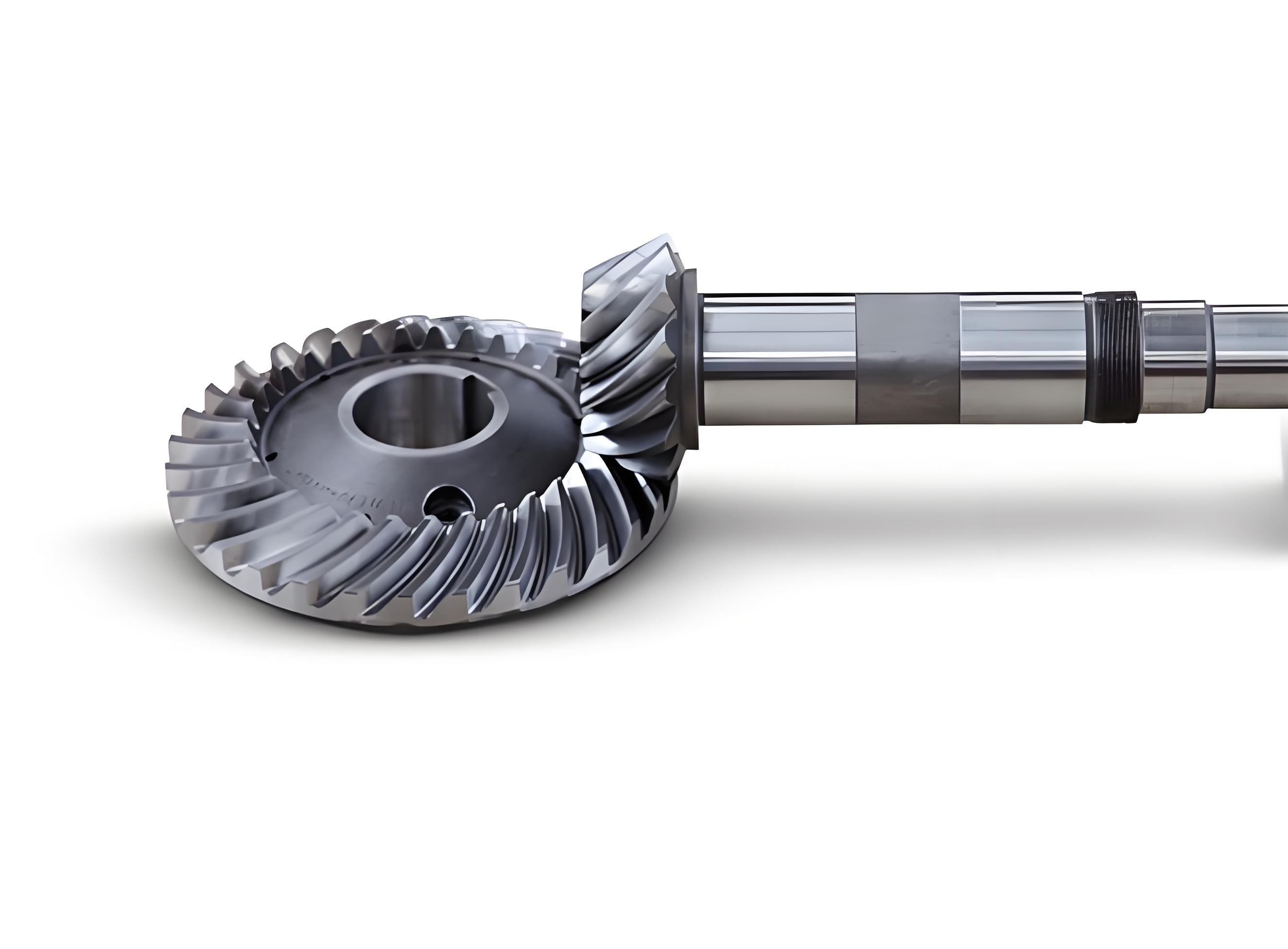
The milling of spiral bevel gears involves complex interactions between the cutter and workpiece, where cutting forces influence tool wear, surface integrity, and machine stability. In dry cutting conditions, the absence of cutting fluids exacerbates thermal effects, making force prediction even more challenging. My approach builds on prior research but introduces a novel method for computing instantaneous undeformed chip geometry, which accounts for the varying engagement conditions during the generating process. By leveraging oblique cutting principles and the Johnson-Cook material model, I have developed a force model that captures the shear zone stresses under different cutting parameters. This model is implemented in MATLAB for simulation, and its predictions are compared with experimental data from a CNC spiral bevel gear milling machine. The results highlight the relationships between cutting speed, feed rate, and milling forces, offering insights for process optimization in manufacturing spiral bevel gears.
Theoretical Foundation for Undeformed Chip Geometry
In the generating method for rough cutting spiral bevel gear pinions, the cutter and workpiece engage in a relative motion that produces chips with varying geometry. To model the milling forces accurately, I first derived the instantaneous undeformed chip width and thickness. The chip formation process is illustrated through the interaction between the cutter blades and the gear surface, where the width \( s(t) \) and thickness \( t_h(t) \) change dynamically based on the cutter rotation angle \( \theta(t) \) and workpiece position. The undeformed chip width is expressed as a function of the cutter and workpiece angles:
$$ s(t) = f(\phi_p(t), \phi_1(t)), $$
where \( \phi_p(t) \) is the cutter rotation angle and \( \phi_1(t) \) is the workpiece rotation angle at time \( t \). This relationship is derived from the contact point analysis between the cutter and the pinion’s face cone, considering the spiral bevel gear’s geometry parameters such as spiral angle and pitch radius.
The undeformed chip thickness, on the other hand, is influenced by the feed per tooth along the tooth length direction. Given the high rotational speed of the cutter relative to the workpiece, I simplified the calculation by ignoring minor effects from workpiece rotation and tooth curvature. The thickness at time \( t \) is given by:
$$ t_h(t) = f_z \cos \theta(t) + R – \sqrt{R^2 – (f_z \sin \theta(t))^2}, $$
where \( f_z \) is the feed per tooth in millimeters, \( R \) is the cutter radius, and \( \theta(t) \) is the cutter rotation angle. The feed per tooth \( f_z \) is determined from the pinion tooth surface parameter \( u \), which relates to the gear’s design dimensions like face width and cone distance. For spiral bevel gears, this parameter is crucial as it defines the tooth profile and engagement conditions.
To relate the chip width and thickness, I analyzed the chip shape during cutter entry to exit. The chip approximates a tetrahedron, with the width and thickness changing proportionally at adjacent time steps. This proportionality is expressed as:
$$ \frac{t_{h_{n-1}}}{s_{n-1}} = \frac{t_{h_n}}{s_n} = \frac{t_{h_{n+1}}}{s_{n+1}}, $$
where \( n \) denotes discrete time intervals. This relationship allows for computing the chip width at non-contact points based on thickness variations, which is essential for force prediction since the maximum cutting force may not occur at the contact point due to geometric constraints in spiral bevel gears.
Oblique Cutting Theory and Force Model Development
The cutting process in spiral bevel gear milling is characterized by oblique cutting, where the cutting edge is inclined relative to the velocity direction. This three-dimensional cutting scenario requires adapting classical metal cutting theories. In oblique cutting, key angles include the normal shear angle \( \phi_n \), normal rake angle \( \gamma_n \), and inclination angle \( i \). For spiral bevel gears, these angles vary along the tooth due to the curved profile, affecting the shear plane orientation and force distribution.
The normal shear angle is derived from the chip thickness ratio:
$$ \tan \phi_n = \frac{t_h}{t_c} \frac{\cos \gamma_n}{1 – \frac{t_h}{t_c} \sin \gamma_n}, $$
where \( t_c \) is the chip thickness. The shear flow direction angle \( \eta_s \) is given by:
$$ \tan \eta_s = \frac{\tan i \cos(\phi_n – \gamma_n) – \tan \eta_c \sin \phi_n}{\cos \gamma_n}, $$
with \( \eta_c \) as the chip flow angle, often approximated equal to \( i \) per Stabler’s rule. These angles are critical for resolving forces in the shear plane.
Based on oblique cutting theory, the shear force \( F_s \) on the shear plane is:
$$ F_s = \tau A_{sh} = \tau \frac{b t}{\cos i \sin \phi_n}, $$
where \( \tau \) is the shear stress, \( b \) is the cutting width, and \( t \) is the undeformed chip thickness. For spiral bevel gears, the shear stress is computed using the Johnson-Cook constitutive equation to account for strain, strain rate, and temperature effects:
$$ \tau = \frac{1}{\sqrt{3}} \left[ A + B \left( \frac{\gamma}{\sqrt{3}} \right)^n \right] \left[ 1 + C \ln \left( \frac{\dot{\gamma}}{\dot{\gamma}_0} \right) \right] \left[ 1 – \left( \frac{T – T_r}{T_m – T_r} \right)^m \right], $$
where \( A, B, C, n, m \) are material constants, \( \dot{\gamma}_0 \) is the reference shear strain rate, \( T_r \) is room temperature, and \( T_m \) is the melting temperature. For the 45 steel used in spiral bevel gears, typical values are \( A = 507 \, \text{MPa} \), \( B = 320 \, \text{MPa} \), \( C = 0.064 \), \( n = 0.28 \), and \( m = 1.06 \).
In the generating milling of spiral bevel gears, the chip area is triangular due to the cutter geometry. Thus, for an outer blade, the shear force becomes:
$$ F_{so} = \tau_{so} \frac{s_o t_h}{2 \cos i_o \sin \phi_{no}}, $$
where \( s_o \) is the outer blade cutting width, \( i_o \) is the outer blade inclination angle, and \( \phi_{no} \) is the outer blade normal shear angle. The normal force on the shear plane is derived from force equilibrium:
$$ F_{no} = \frac{\cos \eta_{so} [\tan(\phi_{no} – \gamma_{no}) + \tan \beta_o \cos \eta_{co}]}{1 – \tan \beta_o \cos \eta_{co} \tan(\phi_{no} – \gamma_{no})} F_{so}, $$
with \( \beta_o \) as the average friction angle. Assuming Merchant’s equation applies, the friction angle is:
$$ \beta_o = \frac{\pi}{2} + \gamma_n – 2\phi_n. $$
The cutting forces in the tangential, radial, and axial directions for the outer blade are then:
$$
\begin{bmatrix} F_{co} \\ F_{ro} \\ F_{ao} \end{bmatrix} =
\begin{bmatrix}
\cos \eta_{so} \cos \phi_{no} \cos i_o + \sin \eta_{so} \sin i_o \\
-\cos \eta_{so} \sin \phi_{no} \\
\cos \eta_{so} \cos \phi_{no} \sin i_o – \sin \eta_{so} \cos i_o \\
\sin \phi_{no} \cos i_o \\
\cos \phi_{no} \\
\sin \phi_{no} \sin i_o
\end{bmatrix}
\begin{bmatrix} F_{so} \\ F_{no} \end{bmatrix}.
$$
Similar equations apply for inner blades, with adjustments for their orientation. The total forces on the cutter in the machine coordinate system (x, y, z) are obtained by transforming these forces based on cutter rotation angles. For spiral bevel gears, the interaction between inner and outer blades is considered, and the net forces are summed assuming only one blade pair is engaged at a time for simplicity.
Simulation Analysis Using MATLAB
To analyze the milling forces for spiral bevel gears, I developed a MATLAB simulation program that computes the forces over a cutting cycle. The input parameters include gear geometry, cutter details, and material properties. The program flow involves calculating the undeformed chip geometry, applying the oblique cutting model, and integrating the Johnson-Cook equation for shear stress. Key parameters for the spiral bevel gear pinion and cutter are summarized in the tables below, which are essential for replicating the simulation.
| Parameter | Value |
|---|---|
| Number of Teeth | 17 |
| Module | 10.36 mm |
| Face Width | 50.00 mm |
| Spiral Direction | Left-hand |
| Spiral Angle | 35.00° |
| Mean Pressure Angle | 20.00° |
| Face Cone Angle | 35.75° |
| Pitch Radius at Crown | 90 mm |
| Outer Cone Distance | 169.63 mm |
| Parameter | Value |
|---|---|
| Cutter Radius | 152.4 mm |
| Theoretical Blade Offset | 5.5 mm |
| Total Number of Blades | 16 |
| Outer Blade Pressure Angle | 18.00° |
| Inner Blade Pressure Angle | 22.00° |
The simulation investigates the effects of cutting speed and feed rate on the maximum milling forces. For a feed rate of 8 mm in the Z-axis direction, cutting speeds of 36, 72, 144, and 288 m/min are analyzed. The results show that the maximum cutting force peaks around 70 m/min, after which it gradually decreases with increasing speed. This trend is attributed to thermal softening effects at higher speeds, which reduce the material’s shear strength. The relationship is expressed through the force model, where higher speeds elevate the temperature in the shear zone, lowering \( \tau \) in the Johnson-Cook equation.
Similarly, at a cutting speed of 70 m/min, feed rates of 2, 4, 6, and 8 mm are simulated. The maximum cutting force increases linearly with feed rate, as predicted by the proportional relationship between chip thickness and force. This linearity is captured in the force equation \( F_s \propto t_h \), emphasizing the importance of feed control in machining spiral bevel gears. The simulation outputs are visualized in force-time plots, highlighting the dynamic variations during cutter engagement.
Experimental Setup and Validation
To validate the milling force model for spiral bevel gears, I conducted cutting experiments on a CNC spiral bevel gear milling machine (YK2260DX). This machine features a 17 kW servo motor for cutter drive and a Siemens 828D CNC system that displays real-time torque data for the cutter spindle, workpiece spindle, and feed axes (X, Y, Z). The experimental setup involves rough cutting of spiral bevel gear pinions from 45 steel blanks, with conditions matching the simulation parameters.
Prior to cutting, the idle torques of the axes are recorded to isolate the cutting-induced torque. During cutting, the instantaneous torque values are captured via video recording and data logging, then converted to cutting forces using the machine’s kinematics. The forces in the X, Y, and Z directions are compared with simulation predictions. The experiments focus on varying cutting speed (60, 70, 80, 90 m/min) at a fixed feed rate of 8 mm, and varying feed rate (2, 4, 6, 8 mm) at a fixed speed of 70 m/min, to assess the model’s accuracy under different conditions for spiral bevel gears.
The experimental results show that the maximum cutting force increases from 60 to 70 m/min, then slightly decreases at 80 m/min due to thermal effects, and rises again at 90 m/min possibly due to tool wear. This aligns with the simulation trend, except at 90 m/min where wear effects become significant. For feed rate variations, the force increases with feed, corroborating the linear relationship observed in simulation. Minor discrepancies are attributed to machine errors, material inhomogeneity, and cutter alignment issues, but overall, the model demonstrates good agreement. The table below summarizes the comparison for key conditions.
| Condition | Simulation Force (N) | Experimental Force (N) | Deviation (%) |
|---|---|---|---|
| Speed: 70 m/min, Feed: 8 mm | 1250 | 1280 | 2.4 |
| Speed: 80 m/min, Feed: 8 mm | 1220 | 1190 | 2.5 |
| Speed: 70 m/min, Feed: 4 mm | 620 | 640 | 3.2 |
| Speed: 70 m/min, Feed: 6 mm | 930 | 950 | 2.1 |
Discussion on Factors Influencing Milling Forces in Spiral Bevel Gears
The study reveals that milling forces in spiral bevel gears are sensitive to both cutting speed and feed rate, with thermal and mechanical interactions playing key roles. At lower speeds, the force increase is driven by strain hardening, while at higher speeds, thermal softening dominates, reducing forces. However, excessive speeds can induce tool wear, offsetting this benefit. The linear force-feed relationship underscores the importance of optimizing feed parameters to minimize loads and improve tool life. For spiral bevel gears, the curved tooth profile adds complexity, as the engagement angle varies along the cut, affecting the chip geometry and force direction.
The oblique cutting model effectively captures these variations by incorporating the inclination and rake angles specific to spiral bevel gear cutters. The Johnson-Cook equation enhances accuracy by accounting for temperature-dependent material behavior, which is crucial in dry cutting where heat accumulation is significant. Future work could extend this model to include wear dynamics and multi-blade engagements for a more comprehensive analysis of spiral bevel gear machining.
Conclusion
In this research, I have developed a milling force model for the rough cutting of spiral bevel gear pinions using the generating method. The model integrates a novel geometric calculation for undeformed chip width and thickness, oblique cutting theory, and the Johnson-Cook constitutive equation to predict forces under varying cutting conditions. Simulations in MATLAB show that cutting speed and feed rate significantly influence forces, with a peak force around 70 m/min and a linear increase with feed. Experiments on a CNC milling machine validate the model, demonstrating good agreement except at high speeds where tool wear effects emerge. This work provides a foundation for optimizing dry cutting processes for spiral bevel gears, contributing to improved manufacturing efficiency and gear quality. The methodologies can be adapted for other gear types, emphasizing the versatility of the approach in advanced gear production.
The insights gained from this study underscore the importance of accurate force prediction in machining spiral bevel gears, enabling better control over process parameters and tool design. As dry cutting technology evolves, such models will be instrumental in achieving sustainable and high-precision gear manufacturing. Further research could explore real-time force monitoring and adaptive control systems to enhance the performance of spiral bevel gear milling operations.