
In the field of mechanical transmission, particularly in aerospace and automotive industries, spiral bevel gears play a critical role due to their high load-carrying capacity, smooth operation, and low noise characteristics. These gears are essential for transmitting power and motion between intersecting shafts, often under demanding conditions. However, during operation, spiral bevel gears can experience abnormal vibrations caused by internal and external excitations, leading to potential failures or excessive wear. Therefore, understanding the vibration mechanisms and modal characteristics of spiral bevel gear systems is paramount for designing reliable and efficient transmissions. This study focuses on developing a comprehensive methodology for system-level modal analysis of spiral bevel gears, incorporating precise tooth surface modeling, pre-stressed modal analysis, experimental validation, and sensitivity studies.
The modal analysis of gear systems has been extensively researched for spur and helical gears, but studies on spiral bevel gears remain limited. Traditional approaches often simplify gear interactions through bonded contacts or use theoretical tooth surfaces that deviate from actual geometries, leading to inaccuracies in modal predictions. To address this gap, we propose a novel framework that integrates accurate tooth surface modeling based on design and machining parameters, finite element analysis (FEA) for static and dynamic assessments, and experimental correlation. This approach ensures a realistic representation of gear meshing behavior, which is crucial for predicting system-level vibrations and avoiding resonance issues.
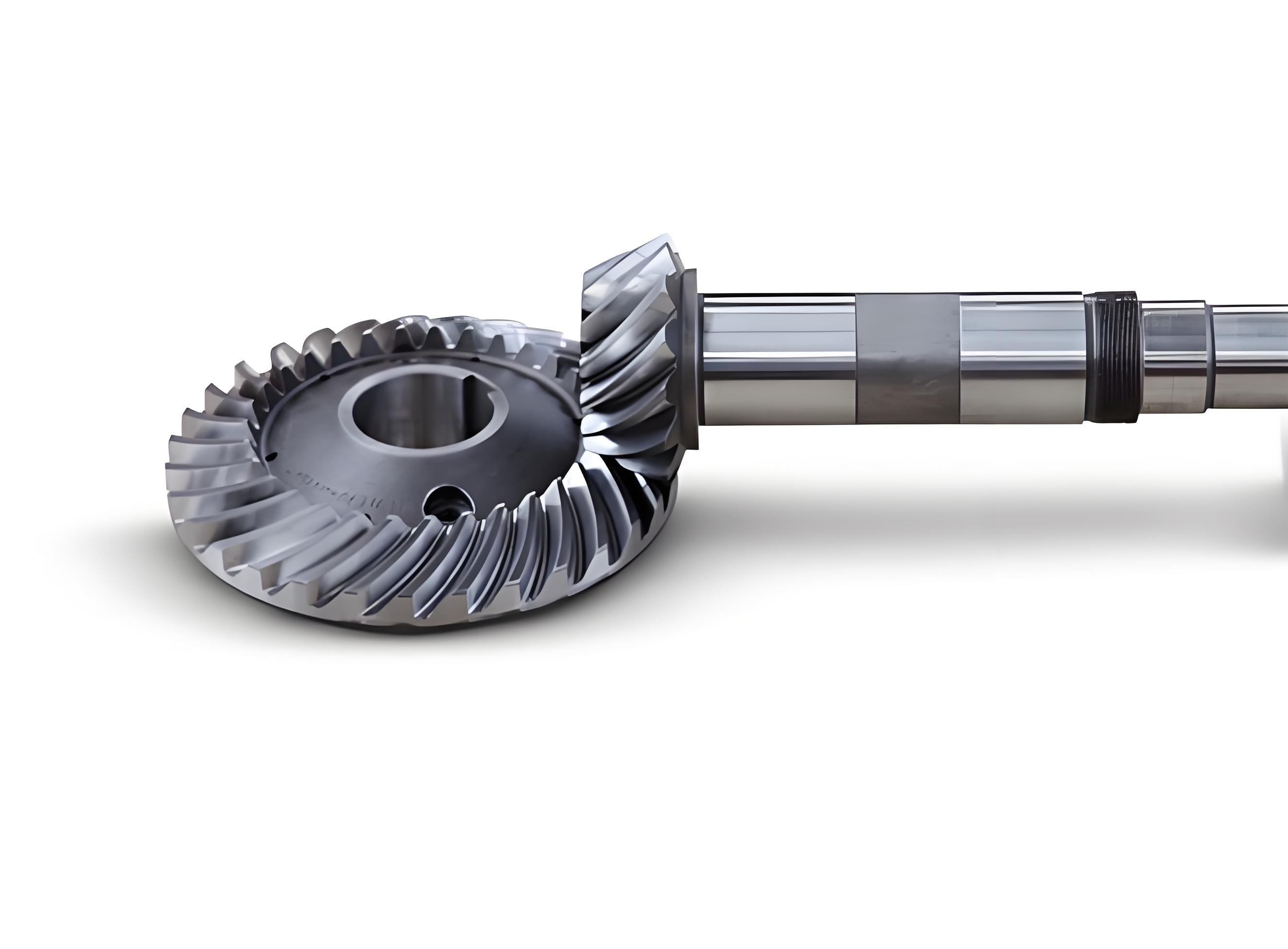
Accurate modeling of spiral bevel gears is foundational to this research. Unlike spur gears, the tooth surfaces of spiral bevel gears are complex and result from a combination of design parameters and machining settings. We start by obtaining tooth surface points using simulation software based on design and machining parameters, as detailed in the following tables. The design parameters, such as number of teeth, module, spiral angle, and pressure angle, define the macro-geometry, while machining parameters, including cutter settings and machine tool adjustments, influence the micro-geometry and contact patterns.
| Parameter | Pinion | Gear |
|---|---|---|
| Number of Teeth | 35 | 37 |
| Module (mm) | 3.2 | 3.2 |
| Mid Spiral Angle (°) | 35 | 35 |
| Normal Pressure Angle (°) | 20 | 20 |
| Shaft Angle (°) | 80 | 80 |
| Face Width (mm) | 24 | 24 |
| Hand of Spiral | Right | Left |
| Outer Cone Distance (mm) | 89.634 | 89.634 |
| Pitch Cone Angle (°) | 38.6648 | 41.3352 |
| Face Angle (°) | 40.859 | 43.3855 |
| Root Angle (°) | 36.6145 | 39.141 |
| Dedendum (mm) | 3.434 | 3.209 |
| Addendum (mm) | 2.607 | 2.833 |
| Parameter | Gear (Concave Side) | Pinion (Convex Side) | Pinion (Concave Side) |
|---|---|---|---|
| Blank Swivel Angle (°) | 61.7443 | 60.265 | 61.5715 |
| Offset (mm) | 0 | 0 | 0 |
| Machine Center to Workpiece Reference (mm) | 0 | -5.42884 | 7.81848 |
| Blank Tilt Angle (°) | 39.3737 | 36.62 | 36.62 |
| Second-Order Modification Coefficient | -0.0129735 | -0.067056 | 0.047363 |
| Third-Order Modification Coefficient | 0.0179555 | 0.0006225 | 0.0240835 |
| Cutter Radius (mm) | 70.30805 | 68.1639 | 74.78439 |
| Ratio of Roll | 1.478227 | 1.507862 | 1.709616 |
| Sliding Base (mm) | -0.21505 | 3.23934 | -4.66347 |
| Cutter Rotation Angle (°) | 206.44 | 27 | 25.5 |
| Cutter Tilt Angle (°) | -0.0561 | 0 | 0 |
| Inner Edge Angle (°) | 22.5016 | 21.45 | – |
| Inner Tip Radius p1 (mm) | 0.7 | 74.676 | – |
| Outer Edge Angle (°) | 20.8422 | – | 19.5 |
| Outer Tip Radius p2 (mm) | 0.7 | – | 79.121 |
| Blade Tip Width (mm) | 1.36 | – | – |
| Radius Rc (mm) | 76.2 | – | – |
The tooth surface points are exported as a grid, typically 7×9 points per tooth, and imported into CAD software to construct spline curves and mesh surfaces. This process yields a three-dimensional model with precise tooth geometry for both the pinion and gear. The gear shafts are modeled separately and assembled with the gear pair, considering material properties such as elastic modulus, density, and Poisson’s ratio for 9310 steel. The complete system model includes bearings represented by stiffness matrices at support locations, as the housing effects are simulated through equivalent spring constraints. The contact between gear teeth is defined with frictional properties to mimic real-world meshing conditions.
The meshing stiffness of spiral bevel gears is a key factor in dynamic behavior. It can be approximated using the potential energy method, where the total mesh stiffness \( k_m \) is derived from bending, shear, and compressive components. For a tooth pair in contact, the stiffness per unit face width can be expressed as:
$$ k_m = \frac{1}{\frac{1}{k_b} + \frac{1}{k_s} + \frac{1}{k_c}} $$
where \( k_b \) is the bending stiffness, \( k_s \) is the shear stiffness, and \( k_c \) is the contact stiffness. These are influenced by tooth geometry and load distribution. For spiral bevel gears, the time-varying mesh stiffness due to changing contact lines introduces excitations that affect modal responses. In our model, this is captured through the pre-stressed modal analysis, which accounts for the static load effects on the system’s natural frequencies and mode shapes.
Static analysis is performed to ensure proper contact between the spiral bevel gear teeth under a nominal torque of 100 N·m applied to the pinion. The contact pattern and stress distribution are evaluated to confirm normal meshing without edge loading or excessive stress concentrations. The maximum contact stress is found to be around 275 MPa, indicating satisfactory performance. This static solution serves as the pre-stress condition for subsequent modal analysis, as the gear mesh stiffness and system stiffness matrix are altered by the load.
Pre-stressed modal analysis extracts the natural frequencies and mode shapes of the spiral bevel gear system by solving the eigenvalue problem:
$$ (K – \omega_i^2 M) \phi_i = 0 $$
where \( K \) is the stiffness matrix including pre-stress effects, \( M \) is the mass matrix, \( \omega_i \) is the natural frequency in rad/s for the i-th mode, and \( \phi_i \) is the corresponding mode shape vector. The analysis covers frequencies up to 22 kHz, revealing numerous modes involving diametral and coupled vibrations. Unlike individual gear analyses, the system-level modes show interactions between the pinion and gear, leading to complex patterns such as combined diametral and umbrella modes. Selected modal frequencies and descriptions are summarized below.
| Mode Order | Frequency (Hz) | Description (Pinion/Gear) |
|---|---|---|
| 1 | 4063.9 / 4314.1 | First diametral / – |
| 2 | 5508.7 | – / First diametral |
| 3 | 5705.1 | Second diametral / First diametral |
| 4 | 6022.8 | Second diametral / – |
| 5 | 6172.5 | Second diametral / Second diametral |
| 6 | 6361.3 | Coupled / Second diametral |
| 7 | 6541.6 | Coupled / Second diametral |
| 8 | 6543.7 | Umbrella / Second diametral |
| 9 | 6559.5 | Coupled / Second diametral |
| 10 | 7241.3 | Second diametral / Second diametral |
| 11 | 8159.7 | – / Umbrella |
| 12 | 8778.6 | Coupled (Umbrella + Diametral) / Umbrella + Diametral |
| 13 | 12048 | Third diametral / Third diametral |
| 14 | 12220 | Third diametral / Third diametral |
| 15 | 12650 | Torsional / Third diametral |
| 16 | 12849 / 12926 | – / Third diametral |
| 17 | 13731 | Third diametral / Coupled |
| 18 | 17644 / 17729 | Umbrella / – |
| 19 | 19360 / 19458 | Fourth diametral / Fourth diametral |
| 20 | 20853 / 21082 | – / Fourth diametral |
Experimental validation is conducted on a spiral bevel gearbox test rig representing an aero-engine application. The setup includes the gear pair, shafts, and supports with stiffness values matching the simulation inputs. A torque of 100 N·m is applied via a loading bar to engage the gears, followed by locking with fixtures for modal testing. The impact hammer method is used with multiple response points to capture frequency response functions (FRFs). The modal parameters are extracted using curve-fitting techniques, and the Modal Assurance Criterion (MAC) is applied to ensure orthogonality and reliability of the identified modes.
| Mode Order | Frequency (Hz) | Description (Pinion/Gear) |
|---|---|---|
| 1 | 4782 | First diametral + Bending / – |
| 2 | 5416 | Second diametral / – |
| 3 | 5760 | Second diametral / Second diametral |
| 4 | 6429 | Second diametral + Bending / – |
| 5 | 6633 | Second diametral + Bending / Second diametral + Bending |
| 6 | 6685 | Second diametral + Bending / Second diametral + Bending |
| 7 | 7562 | Umbrella + Bending / – |
| 8 | 11878 | Third diametral / – |
| 9 | 12558 | – / Third diametral |
| 10 | 17381 | Bending / – |
| 11 | 19159 | Fourth diametral + Bending / – |
| 12 | 20025 | Fourth diametral + Bending / – |
Comparing simulation and experimental results, the frequencies for diametral modes show discrepancies within 10.08%, which is acceptable for engineering applications. For instance, the first diametral mode of the pinion has a simulated frequency of 4314.1 Hz versus an experimental value of 4782 Hz, an error of 10.85%. The second diametral modes exhibit errors around 6-10%, while higher-order modes like the third and fourth diametral show better agreement with errors below 2.5%. The mode shapes correlate well, though some experimental modes include bending components due to fixture influences. This validation confirms that the pre-stressed modal analysis method based on accurate tooth surfaces is effective for predicting system-level dynamics of spiral bevel gears.
Sensitivity analysis is performed to assess the impact of different contact surfaces and loads on the modal characteristics of spiral bevel gears. In practice, both convex and concave sides of spiral bevel gears can be working surfaces, and operating loads may vary. Four cases are considered: Case 1 uses pinion convex against gear concave with 100 N·m torque; Case 2 uses pinion concave against gear convex with 50 N·m; Case 3 uses pinion concave against gear convex with 100 N·m; and Case 4 uses the same contact as Case 3 with 130 N·m. The results indicate that changing the contact surface significantly alters the modal frequencies and mode shapes, while load variations have a minor effect within the tested range.
| Mode Description | Frequency Case 1 (Hz) | Frequency Case 3 (Hz) | Error (%) |
|---|---|---|---|
| Pinion First Diametral | 4063.9 / 4314.1 | 4112.4 / 4315 | -1.18 / -0.02 |
| Gear First Diametral | 5508.7 | 5500.8 | 0.14 |
| Pinion Second Diametral | 5705.1 | 5644.8 | 1.07 |
| Coupled Mode | 6541.6 | 6536.9 | 0.07 |
| Umbrella Mode | 8159.7 | 7886 | 3.47 |
| Pinion Third Diametral | 12048 | 12060 | -0.10 |
| Pinion Fourth Diametral | 19360 / 19458 | 19364 / 19530 | -0.02 / -0.37 |
The contact surface sensitivity arises because different sides of spiral bevel gears have distinct curvature distributions and contact paths, leading to variations in mesh stiffness. The effective mesh stiffness \( k_{eff} \) for a given contact can be modeled as a function of the contact ellipse dimensions and pressure distribution, derived from Hertzian contact theory:
$$ k_{eff} = \frac{\pi E^* a b}{2(1 – \nu^2) \sqrt{a^2 + b^2}} $$
where \( E^* \) is the equivalent Young’s modulus, \( \nu \) is Poisson’s ratio, and \( a \) and \( b \) are the semi-axes of the contact ellipse. Changes in contact surface alter \( a \) and \( b \), thereby modifying \( k_{eff} \) and the system’s dynamic properties. This explains why modal frequencies shift noticeably between convex-concave and concave-convex engagements.
| Mode Description | Frequency Case 2 (50 N·m) (Hz) | Frequency Case 3 (100 N·m) (Hz) | Frequency Case 4 (130 N·m) (Hz) | Error Case 2 vs 3 (%) | Error Case 4 vs 3 (%) |
|---|---|---|---|---|---|
| Pinion First Diametral | 4104.3 / 4299.7 | 4112.4 / 4315 | 4122.5 / 4316.2 | -0.20 / -0.35 | 0.25 / 0.03 |
| Gear First Diametral | 5500.2 | 5500.8 | 5501.3 | -0.01 | 0.01 |
| Pinion Second Diametral | 5623 | 5644.8 | 5646.2 | -0.39 | 0.02 |
| Coupled Mode | 6536.3 | 6536.9 | 6537.1 | -0.01 | 0.00 |
| Umbrella Mode | 7878.1 | 7886 | 7889.3 | -0.10 | 0.04 |
| Pinion Third Diametral | 12052 | 12060 | 12063 | -0.07 | 0.02 |
| Pinion Fourth Diametral | 19360 / 19511 | 19364 / 19530 | 19366 / 19538 | -0.02 / -0.10 | 0.01 / 0.04 |
Load sensitivity is less pronounced because increasing torque primarily enlarges the contact area without drastically changing the mesh stiffness profile. The relationship between load \( F \) and contact semi-axis \( a \) can be expressed as \( a \propto F^{1/3} \) for elliptical contacts, implying that stiffness variations are sub-linear. Thus, within a typical operating range (e.g., 50 to 130 N·m), the natural frequency changes are below 2.5%, allowing engineers to neglect load effects in preliminary modal assessments for spiral bevel gears. However, for high-precision applications, it is advisable to conduct analyses at multiple load levels.
The dynamic response of spiral bevel gear systems can further be analyzed using the equation of motion:
$$ M \ddot{x} + C \dot{x} + K x = F(t) $$
where \( M \), \( C \), and \( K \) are the mass, damping, and stiffness matrices, respectively; \( x \) is the displacement vector; and \( F(t) \) is the time-varying excitation force from gear meshing. The natural frequencies \( \omega_i \) are the square roots of the eigenvalues of \( M^{-1}K \), and mode shapes are the eigenvectors. Damping ratios \( \zeta_i \) are estimated from experimental data or assumed based on material properties. For spiral bevel gears, the excitation \( F(t) \) includes components at the mesh frequency and its harmonics, which can coincide with natural frequencies to cause resonance. Therefore, accurate modal analysis helps in identifying critical speeds and designing avoidance strategies.
In conclusion, this study presents a robust methodology for system-level modal analysis of spiral bevel gears, emphasizing the importance of accurate tooth surface modeling and pre-stressed conditions. The proposed approach integrates finite element simulations with experimental validation, demonstrating good agreement for diametral and coupled modes. Sensitivity analyses reveal that spiral bevel gear systems are highly sensitive to contact surface variations due to changes in mesh stiffness, while load effects are negligible within typical operational ranges. These insights enable engineers to perform reliable vibration assessments and optimize gear designs for aerospace and other high-performance applications. Future work could explore nonlinear effects, such as backlash and time-varying mesh stiffness, in more detail to enhance predictive capabilities.
The methodology outlined here not only advances the understanding of spiral bevel gear dynamics but also provides a practical toolkit for modal analysis in engineering design. By leveraging precise modeling and comprehensive testing, we can mitigate vibration-related issues and improve the reliability and efficiency of gear transmissions. As spiral bevel gears continue to be integral components in advanced machinery, ongoing research into their dynamic behavior will remain crucial for innovation and performance enhancement.