
The design of spiral bevel gears is a cornerstone in the development of high-performance mechanical power transmission systems for intersecting or offset shafts. Their superior characteristics, including high load capacity, smooth operation, and significant overlap ratio, make them indispensable in demanding applications such as automotive differentials, helicopter rotor drives, heavy machinery, and precision machine tools. The performance, efficiency, noise level, and service life of these entire systems are profoundly influenced by the geometric accuracy and quality of the spiral bevel gears at their heart.
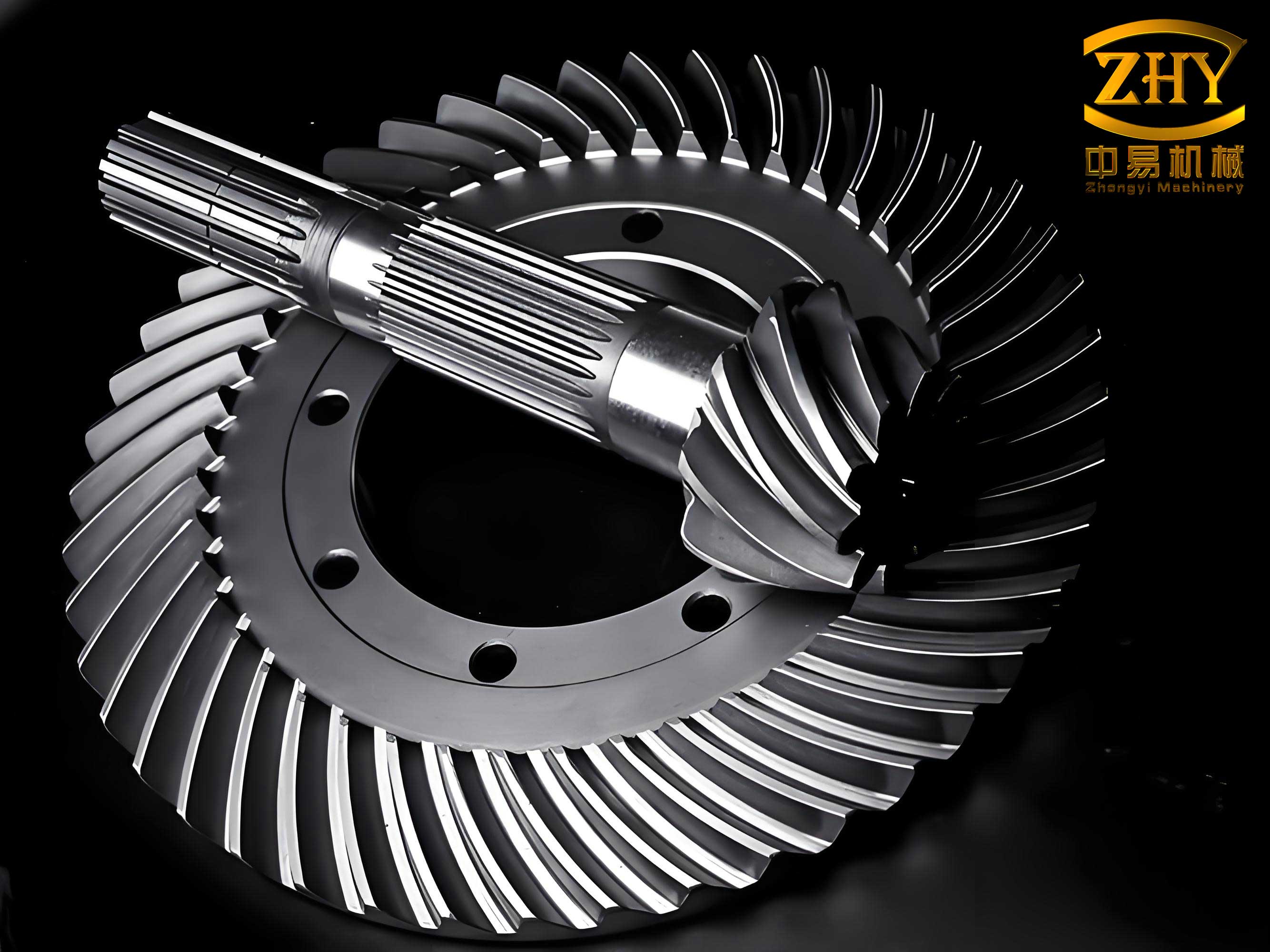
However, the design process for spiral bevel gears is notoriously complex and iterative. It is not a simple linear calculation but a multi-stage, knowledge-intensive endeavor requiring constant trade-offs and optimizations across multiple domains. The process typically involves a sequence of interdependent stages: initial parameter selection based on load requirements, material and heat treatment choice, preliminary geometric calculations, structural design, comprehensive strength analysis (contact and bending), and finally, detailed analysis of meshing characteristics, contact patterns, and noise. Each stage relies on the previous one’s outputs and provides feedback that may necessitate revisiting earlier decisions. This process is laden with intricate formulas, table lookups, chart interpretations, and empirical coefficient selections, demanding that engineers possess deep domain expertise, extensive practical experience, and creative problem-solving skills. Traditional manual methods are not only time-consuming and inefficient but also prone to inconsistencies, leading to prolonged development cycles and suboptimal designs. This context creates a compelling need for a systematic, intelligent, and automated approach to designing spiral bevel gears.
In response to these challenges, I have researched and developed an intelligent design system that synergistically integrates Knowledge-Based Engineering (KBE), parametric modeling, and advanced reasoning techniques. The core objective is to encapsulate valuable design knowledge—both explicit (standards, formulas) and tacit (expert heuristics, past successful cases)—within a computational framework. This system guides the engineer through the design process, automates routine calculations and checks, facilitates rapid exploration of design alternatives, and ultimately generates validated parametric models, thereby dramatically enhancing design efficiency, quality, and knowledge reuse.
Architecture of the Intelligent Design System for Spiral Bevel Gears
The proposed system is built upon a three-layer architecture that seamlessly connects knowledge management, intelligent reasoning, and automated geometry generation. This structure ensures a smooth flow from design intent to a manufacturable digital model.
The system architecture comprises the following core components:
- Knowledge Base Management System: This is the repository of all domain intelligence. It is further divided into:
- Database System: Manages static data (material properties, standard tolerances), process parameters, and explanatory information.
- Knowledge Base System: Stores the formalized design knowledge. This includes a Case Library of past successful spiral bevel gear designs, a Rule Base containing design rules and heuristics, and various Constraint Libraries defining geometric and functional limits.
- Inference Engine System: This is the “brain” of the system. It employs a hybrid reasoning model to solve new design problems by utilizing the stored knowledge. It consists of:
- A Case-Based Reasoning (CBR) engine for retrieving and adapting similar past solutions.
- A Rule-Based Reasoning (RBR) engine, powered by the CLIPS expert system shell, for logical deduction and calculation based on encoded rules.
- An Explanation Mechanism to justify the system’s recommendations.
- Parametric Modeling System: This subsystem translates the design parameters derived by the inference engine into precise geometry. It includes:
- A CAD Parametric Drawing module that generates 2D engineering drawings within AutoCAD using ObjectARX.
- A 3D Parametric Modeling module that creates fully defined solid models of the gear pair and assembly in a CAD environment like SolidWorks.
The user interacts with the system through a unified interface. A design request is processed by the inference engine, which searches the knowledge base. The resulting design solution is passed to the parametric modeling system for geometry generation and validation. Successful new designs are then stored back into the case library, enabling continuous learning and expansion of the system’s knowledge.
Key Technologies in the Intelligent Design System
The effectiveness of the system hinges on the robust implementation of several key technologies: the representation of diverse knowledge types, the mechanism for intelligently utilizing that knowledge (reasoning), and the method for converting symbolic design data into precise geometric models.
Knowledge Representation for Spiral Bevel Gears
The design knowledge for spiral bevel gears is multifaceted. It can be broadly categorized as shown in the table below:
| Knowledge Category | Description | Examples |
|---|---|---|
| Textual/Standard Knowledge | Explicit knowledge from published sources. | AGMA/ISO standards, design handbooks, material datasheets, company catalogs. |
| Procedural/Calculative Knowledge | Step-by-step processes, formulas, and algorithms. | Geometry calculation sequences, strength rating formulas (e.g., contact stress $ \sigma_H $, bending stress $ \sigma_F $), optimization procedures. |
| Heuristic/Expert Knowledge | Rules of thumb, experiential judgments, and best practices. | “For high-speed applications, use case-hardened steel.” “Limit the face width to 30% of the cone distance for stability.” |
| Case-Based/Instance Knowledge | Documented records of past successful designs. | Complete parameter sets, performance data, and CAD models of previously manufactured and validated spiral bevel gears. |
To effectively capture this spectrum, a hybrid knowledge representation scheme is employed:
- Production Rules: Ideal for representing heuristic and procedural knowledge. They follow the IF-THEN structure. In the CLIPS syntax, they are defined as:
(defrule rule-name "comment"
    (condition-1)
    (condition-2)
    ...
    =>
    (action-1)
    (action-2)
    ...)
Rules can be factual, calculative, or judgmental. For example, a judgmental rule for selecting the spiral angle $ \beta $ might be:
(defrule select-spiral-angle "Rule for selecting spiral angle based on application"
    (application-type high-speed)
    (module ?m&:(> ?m 3))
    =>
    (assert (spiral-angle 35)))
A calculative rule for determining the transverse contact ratio $ \epsilon_{\alpha} $ could be encapsulated as a function call:
(defrule calculate-transverse-contact-ratio (pinion-teeth ?z1) (gear-teeth ?z2) (pressure-angle ?alpha) (operating-center-distance ?a) ... => (bind ?epsilon_alpha (compute-epsilon-alpha ?z1 ?z2 ?alpha ?a ...)) (assert (transverse-contact-ratio ?epsilon_alpha))) - Object-Oriented Representation: Perfect for modeling case-based knowledge. Each successful design of spiral bevel gears is represented as an instance of a class. The class encapsulates all relevant attributes and methods. For instance, a C++ class structure might be:
class SpiralBevelGearCase {
private:
    // Design Requirements
    string application;
    double input_power;
    double input_speed;
    double gear_ratio;
    // Geometric Parameters
    int teeth_pinion, teeth_gear;
    double module_normal;
    double spiral_angle;
    double face_width;
    // Material & Process
    string material_pinion, material_gear;
    string heat_treatment;
    int quality_grade;
    // Performance Results
    double contact_safety_factor;
    double bending_safety_factor;
    string CAD_model_path;
public:
    // Methods for calculation, retrieval, similarity assessment
    double computeSimilarity(SpiralBevelGearCase ⌖);
    void adaptParameters(SpiralBevelGearCase ⌖);
    ...
};
Hybrid Reasoning Mechanism
The reasoning strategy combines the strengths of Case-Based Reasoning (CBR) and Rule-Based Reasoning (RBR) to efficiently navigate the solution space for new spiral bevel gear designs.
1. Case-Based Reasoning (CBR) Cycle: For a new design problem (target case), the system first searches the case library for the most similar past cases. The similarity between a target case $T$ and a source case $S$ in the library is computed using a weighted nearest-neighbor algorithm:
$$ \text{SIM}(T, S) = \frac{\sum_{i=1}^{n} w_i \cdot \text{sim}(t_i, s_i)}{\sum_{i=1}^{n} w_i} $$
where $n$ is the number of attributes used for retrieval, $w_i$ is the importance weight of the $i$-th attribute, and $\text{sim}(t_i, s_i)$ is a local similarity function for that attribute (e.g., a normalized difference for numerical parameters, exact match for categorical ones). Key retrieval attributes for spiral bevel gears include power, speed, ratio, and center distance.
If the similarity score of the best-matching case exceeds a predefined threshold, it is retrieved and presented to the designer. The system can then assist in adapting this case to meet the specific requirements of the new problem, providing a rapid and proven starting point.
2. Rule-Based Reasoning (RBR) with CLIPS: If no sufficiently similar case is found, or if certain aspects of a retrieved case need modification, the system switches to rule-based reasoning. The initial design requirements and parameters are asserted as facts into CLIPS’s working memory. The inference engine then uses the Rete pattern-matching algorithm to efficiently identify all rules whose conditions (left-hand sides) are satisfied by the current facts. The Rete algorithm’s strength is its network-based approach that stores partial matches, making it extremely fast even with thousands of rules—a necessity for the complex domain of spiral bevel gear design. Activated rules fire, executing their actions (right-hand sides), which may assert new facts, modify existing ones, or call external calculation functions. This forward-chaining process continues until no more rules are activated, culminating in a complete set of derived design parameters.
The hybrid process flow ensures efficiency and robustness: CBR provides quick, experiential solutions when available, while RBR offers a fundamental, rule-driven synthesis capability for novel or highly specific design challenges. The table below summarizes this hybrid approach.
| Aspect | Case-Based Reasoning (CBR) | Rule-Based Reasoning (RBR) | Hybrid Advantage |
|---|---|---|---|
| Basis | Past concrete instances (cases). | General principles and heuristics (rules). | Leverages both specific experience and general knowledge. |
| Strength | Fast, intuitive, good for routine/standard designs. | Systematic, exhaustive, good for novel or constrained problems. | Efficiently handles both routine and novel spiral bevel gear design tasks. |
| Process | RETRIEVE -> REUSE -> REVISE -> RETAIN. | Pattern Matching (Rete) -> Rule Activation -> Execution. | CBR retrieves a starting point; RBR refines and validates it. |
| Role in System | Primary search for initial solution; knowledge accumulation. | Detailed parameter calculation, constraint checking, adaptation logic. | Seamless handoff between reasoning modes provides guided, reliable design. |
Parametric Modeling and CAD Integration
Translating the symbolic design parameters generated by the inference engine into accurate, editable, and manufacturable geometry is a critical final step. The parametric modeling system addresses the unique challenge of spiral bevel gears, whose geometry is complex and not easily defined by simple, fixed topological sketches.
The system operates on two levels:
- 2D Drawing Generation: Using ObjectARX for AutoCAD customization, the system implements a knowledge-driven drawing generation module. It does not merely insert a static block; instead, it uses specific “CAD Drawing Rules” from the knowledge base to dynamically construct the gear’s detailed drawing. These rules define the sequence of geometric entities, their constraints (e.g., concentricity, tangency), and how they relate to the critical design parameters (module, pressure angle, spiral angle, number of teeth). This results in a fully parametric and associative 2D drawing that updates automatically if the underlying design parameters change.
- 3D Solid Modeling: The finalized parameters are then passed to a 3D CAD system like SolidWorks via its API. The system employs a feature-based parametric modeling approach. A master template or a series of macro-driven feature creation steps are used to construct the precise tooth geometry based on advanced generation principles (e.g., Gleason or Klingelnberg systems). The core formulas for generating the tooth flank coordinates are embedded here. For example, the basic relationship for calculating the pitch cone angle $ \delta $ for the pinion in a 90° shaft angle setup is:
$$ \delta_1 = \arctan\left(\frac{z_1}{z_2}\right) $$
where $z_1$ and $z_2$ are the numbers of teeth. The 3D model of the gear pair and their assembly is generated automatically, ready for downstream Finite Element Analysis (FEA) for stress verification or for export to CAM systems.
The integration ensures that the intelligent design process culminates in a precise digital twin of the spiral bevel gears, bridging the gap between conceptual design and manufacturing preparation.
System Implementation and Practical Workflow
The system is implemented using a client-server architecture. A backend database (e.g., Microsoft SQL Server) stores the case library, rule base, and material databases. The reasoning core, built around CLIPS, is integrated with a front-end application developed in a language like C++. This application manages the user interface, coordinates the hybrid inference process, and handles communication with the CAD systems via their respective APIs (ObjectARX for AutoCAD, SolidWorks API).
A typical design workflow for a new set of spiral bevel gears proceeds as follows:
- Input Design Requirements: The engineer specifies the operational conditions: input power $P$ (kW), input speed $n_1$ (rpm), gear ratio $i$, desired center distance $a$ (mm), operating environment, and any special constraints.
- Hybrid Inference Process:
- The system first computes similarity scores between the input requirements and all cases in the library.
- If a highly similar case exists (e.g., SIM > 0.85), it is retrieved. The engineer can review it and use the system’s adaptation rules to tweak parameters like face width or material grade.
- If no suitable case is found, the system initiates a rule-based session. Starting facts are created from the input. Rules fire to select materials, calculate approximate module $m_n$ from bending strength:
$$ m_n \geq \sqrt[3]{\frac{2 K T_1 Y_\epsilon Y_\beta}{\psi_d z_1^2} \cdot \frac{Y_{Fa} Y_{Sa}}{[\sigma_F]}} $$
and then proceed through a comprehensive sequence to determine all geometric parameters, safety factors for contact stress:
$$ \sigma_H = Z_H Z_E Z_\epsilon Z_\beta \sqrt{\frac{2 K T_1}{d_1^2 b} \cdot \frac{u+1}{u}} \leq [\sigma_H] $$
and other performance metrics.
- Design Validation & Iteration: The proposed design is evaluated against all constraints. If checks fail (e.g., safety factor too low), the inference engine suggests modifications (increase face width $b$, change material, adjust heat treatment) and re-runs the calculations.
- Automated Drawing and Modeling: Once a satisfactory design is confirmed, the engineer triggers the CAD modules. The 2D drawing is generated in AutoCAD with all standard views, dimensions, and a gear data table. Subsequently, the 3D parametric models of the pinion, gear, and their assembly are created in SolidWorks.
- Knowledge Retention: After final approval, the complete design, along with its performance data and associated model files, is stored as a new case in the library, enriching the system’s knowledge for future projects.
Conclusion
The development and application of this intelligent design system represent a significant advancement in the methodology for creating spiral bevel gears. By systematically capturing and formalizing the extensive and complex body of knowledge associated with their design—encompassing standards, analytical formulas, expert heuristics, and historical successes—the system transforms a traditionally manual, expertise-heavy, and iterative process into a streamlined, guided, and highly efficient digital workflow. The implementation of a hybrid CBR-RBR inference mechanism ensures both the rapid reuse of proven solutions and the robust synthesis of novel designs. The tight integration with industry-standard CAD platforms via parametric modeling closes the loop, ensuring that intelligent design decisions are directly and accurately manifested in manufacturable geometry.
Practical deployment in industrial settings has demonstrated tangible benefits: a drastic reduction in design cycle time, minimized human error, consistent adherence to design standards and best practices, and effective preservation of corporate design knowledge. Engineers are empowered to explore more design alternatives and optimize performance with greater confidence. This intelligent system, therefore, serves not just as a design automation tool, but as a collaborative partner that amplifies engineering expertise, ultimately leading to higher-performance, more reliable, and more competitively developed spiral bevel gears.