
In the evolving landscape of the automotive industry, awareness regarding noise pollution has deepened significantly. The noise emitted by a vehicle’s rear axle has consequently become a critical metric for assessing overall vehicle quality. As the primary transmission components within the axle, spiral bevel gears are central to this acoustic performance. Therefore, developing and implementing effective methods to mitigate their noise has become an imperative practical challenge for gear manufacturers. This analysis draws upon extensive production and testing experience, focusing on strategies for controlling and reducing noise in spiral bevel gears for light-truck rear axles.
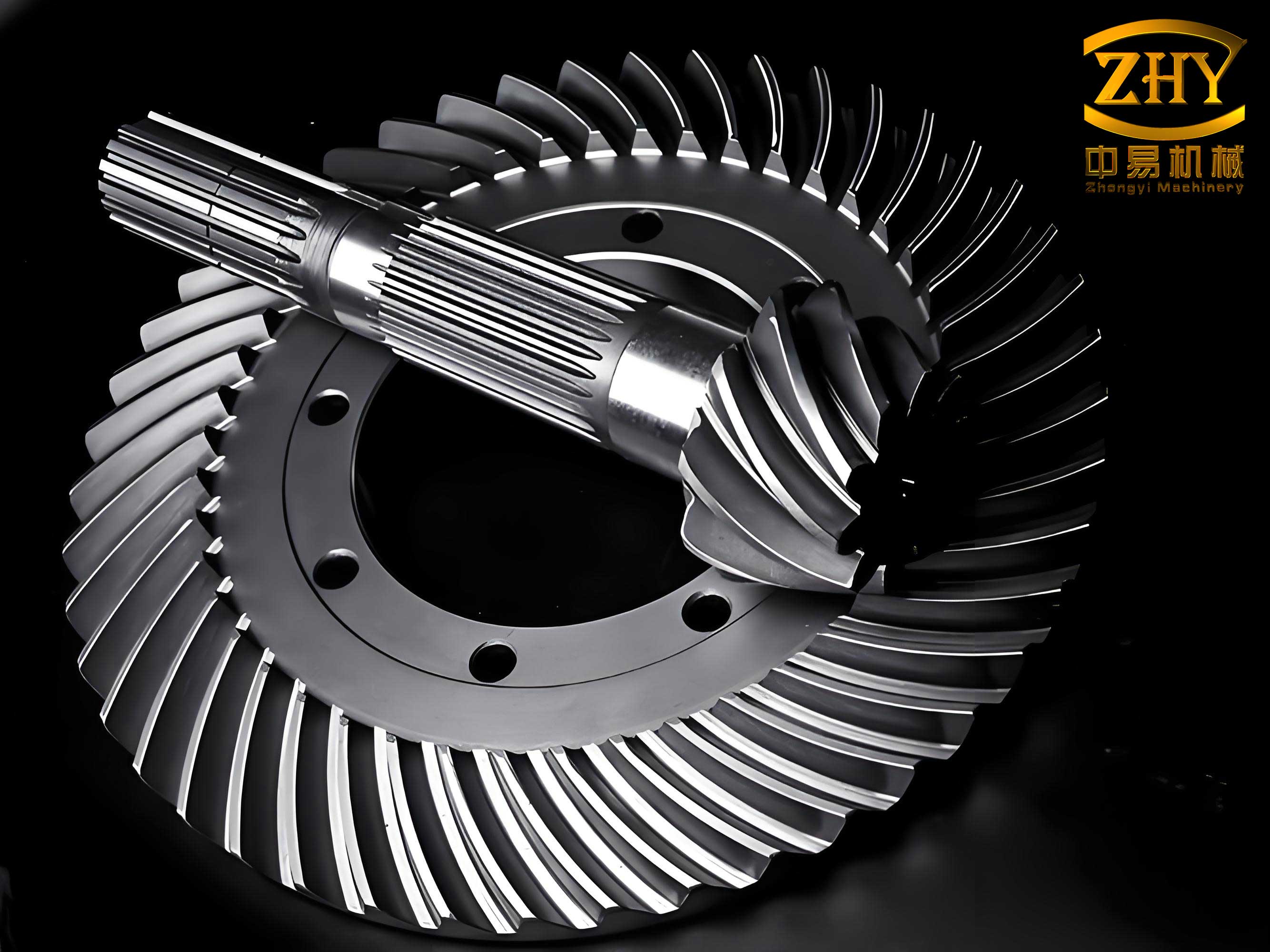
The fundamental cause of gear noise is vibration. When a gear tooth pair meshes, the cyclical engagement inevitably excites vibrations. These vibrations cause pressure waves in the surrounding air, which propagate as sound. The key characteristics of sound are amplitude (loudness) and frequency (pitch). Sound becomes classified as noise when it exceeds certain amplitude thresholds or occurs at unpleasant frequencies. For spiral bevel gears, the primary excitation sources are frictional forces from sliding contact between tooth flanks and impact forces resulting from manufacturing errors, assembly misalignments, and load-induced deformations. This vibration and operational instability are the root causes of gear whine, a prominent type of gear noise.
Root Cause Analysis: Vibration and Excitation in Spiral Bevel Gears
The dynamic excitation in a gear mesh can be modeled by considering the transmission error, which is the deviation between the actual position of the driven gear and its ideal position. A primary component is the mesh stiffness variation, $k_m(t)$, which fluctuates periodically as the number of teeth in contact changes. The equation of motion for a simplified gear pair can be expressed as:
$$I_p \ddot{\theta}_p + c (\dot{\theta}_p – \dot{\theta}_g) + k_m(t) (R_p \theta_p – R_g \theta_g – e(t)) = T_p$$
$$I_g \ddot{\theta}_g – c (\dot{\theta}_p – \dot{\theta}_g) – k_m(t) (R_p \theta_p – R_g \theta_g – e(t)) = -T_g$$
where $I_p$, $I_g$ are polar moments of inertia, $\theta_p$, $\theta_g$ are angular displacements, $c$ is a damping coefficient, $R_p$, $R_g$ are base radii, $e(t)$ is the static transmission error (a key noise contributor), and $T_p$, $T_g$ are torques. The term $e(t)$ encapsulates the composite effect of tooth profile deviations, pitch errors, and alignment errors. Minimizing $e(t)$ and smoothing the variation of $k_m(t)$ are fundamental to noise reduction.
Method 1: Optimization of Gear Design Parameters and Manufacturing Process
The first line of defense against noise is optimal design and precise manufacturing. Key parameters for spiral bevel gears were targeted for improvement.
1.1 Increasing the Pinion Mean Spiral Angle
The spiral angle ($\beta_m$) directly influences the face contact ratio, $m_F$, also known as the overlap ratio. A higher spiral angle increases $m_F$, promoting smoother torque transfer by ensuring more than one tooth pair is in contact for a larger portion of the mesh cycle. The face contact ratio can be approximated by:
$$m_F \approx \frac{F \tan \beta_m}{p_t}$$
where $F$ is the face width and $p_t$ is the transverse circular pitch. For a specific light-truck axle application, the pinion mean spiral angle was increased from an original design of $35^\circ$ to $38^\circ$. This modification, verified via gear calculation software to ensure bending strength and bearing load capacity, significantly enhanced meshing smoothness.
1.2 Increasing the Gear Face Width
While excessive face width can lead to thin tooling and undercut at the toe, a judicious increase improves both contact ratio and load capacity without major cost implications. For the subject gear set, the gear face width was increased from 32 mm to 35 mm. This change further contributed to a higher total contact ratio ($m_\gamma = m_F + m_a$, where $m_a$ is the transverse contact ratio), damping vibrations.
1.3 Reducing Finishing Allowance in Gear Cutting
The amount of stock left for the finishing cut in gear generation has profound effects. A large finishing allowance necessitates a narrower roughing tool top land, which weakens the tool and can lead to poorer root fillet quality and higher surface roughness on the tooth flanks. Increased surface roughness ($R_a$) exacerbates friction-induced vibrations. The finishing allowance was reduced from 0.45 mm to 0.30 mm per flank. This allowed for a more robust roughing tool and created a better starting condition for the final cut, yielding a superior surface finish.
The cumulative effect of these parameter and process optimizations is summarized in Table 1. Noise testing was conducted under controlled conditions with a fixed rotational speed.
| Gear Set Configuration | Number of Sets Tested | Rotational Speed (rpm) | Average Noise Level (dB) | Comments |
|---|---|---|---|---|
| Original Design Specification | 5 | 1500 | 86.5 (Drive Side) 87.2 (Coast Side) |
Baseline measurement. |
| Optimized Parameters & Process | 5 | 1500 | 83.1 (Drive Side) 83.8 (Coast Side) |
Significant reduction of ~3.5 dB observed. |
Method 2: Post-Cutting Finishing Operations – Lapping
After heat treatment, gear teeth distort. While grinding is the premium solution for correcting distortion and achieving the finest finish, lapping is a highly cost-effective process for noise reduction in mass-produced spiral bevel gears. The primary functions of lapping are to reduce the surface roughness ($R_a$) and to improve the contact pattern by gently wearing in the mating flanks. Critical to successful lapping are the choice of abrasive grit size, lapping oil viscosity, and the controlled setting of the assembly backlash during the process. Incorrect parameters can cause pitting or scoring, increasing noise. The effectiveness of lapping is demonstrated in Table 2.
| Surface Condition ($R_a$) | Number of Sets Tested | Rotational Speed (rpm) | Average Noise Level (dB) |
|---|---|---|---|
| Unlapped (~2.0 µm) | 5 | 1500 | 85.8 (Drive Side) 86.4 (Coast Side) |
| Lapped (~0.8 µm) | 5 | 1500 | 82.0 (Drive Side) 82.7 (Coast Side) |
The data shows that lapping, by improving surface finish, reduces noise by approximately 3-4 dB. The relationship between friction-induced vibration and surface roughness can be conceptually linked through a damping term influenced by the coefficient of friction, which is lower with smoother surfaces.
Method 3: Precision Control of Backlash and Strategic Hardness Patterning
3.1 Optimal Backlash Control
Backlash ($j$) is essential for proper assembly, lubrication, and thermal expansion. However, it has a non-linear relationship with noise. As illustrated conceptually in the relationship below, insufficient backlash causes binding and high impact forces, increasing noise. A slight increase dampens impacts and reduces noise. However, excessive backlash leads to tooth striking and increased noise levels. The optimal range is narrow and must be tightly controlled during final assembly adjustment.
$$ \text{Noise}(j) \approx A \cdot e^{-B \cdot j} + C \cdot j^2 \quad \text{(for a relevant range of } j\text{)}$$
where $A$, $B$, $C$ are system-dependent constants. Empirical testing determined that for the subject spiral bevel gears, a backlash of 0.15-0.20 mm with a variation of less than 0.05 mm produced the lowest noise, as shown in Table 3.
| Assembly Backlash [mm] | Number of Sets Tested | Average Noise Level (dB) |
|---|---|---|
| 0.10 – 0.12 | 3 | 84.5 |
| 0.15 – 0.18 | 5 | 81.8 |
| 0.22 – 0.25 | 3 | 83.9 |
3.2 Differential Hardness Patterning
While case-hardened “hard” teeth (58-64 HRC) offer superior wear resistance, they transmit vibration more readily than softer, through-hardened teeth (28-35 HRC). In a rear axle, the pinion (fewer teeth) experiences more engagement cycles and is typically the life-limiting component. Strategic heat treatment was employed: pinion tooth flanks were maintained at >58 HRC, while the larger gear’s tooth flanks were controlled to 55-57 HRC. This differential harness pairing leverages the gear’s slightly higher damping capacity to absorb vibrations from the harder pinion, reducing overall noise without compromising durability, as confirmed via road testing. Data is shown in Table 4.
| Heat Treatment Scheme | Tooth Flank Hardness (Pinion/Gear) | Average Noise Level (dB) | Notes |
|---|---|---|---|
| Uniform High Hardness | >58 HRC / >58 HRC | 83.0 | Baseline for hard-hard pairing. |
| Differential Hardness | >58 HRC / 55-57 HRC | 81.2 | ~1.8 dB reduction observed. |
Method 4: Enhancing Contact Pattern Precision
The contact pattern—the area of tooth flank contact under load—is paramount for noise and durability. Its shape, location, and size must be meticulously controlled during gear cutting and adjusted for heat treatment distortion.
- Location: A pattern too close to the toe (inner end) or heel (outer end) can run off the edge under load, causing localized high stress and a pronounced whine. The pattern must be centered longitudinally.
- Size: A short contact pattern indicates high localized stress and poor load distribution, leading to impact and high noise. For light-truck spiral bevel gears, the contact length should be 50-70% of the face width to ensure robust, quiet operation. The contact ratio $m_\gamma$ is directly related to pattern length.
- Shape: A balanced, elliptical shape is ideal. “Free-floating” patterns that move significantly under test are indicators of sensitivity to alignment and potential sources of variable noise.
Controlling the contact pattern requires precise machine settings in the gear generator (considering machine root angle, cutter head tilt, etc.) and a predictable, consistent heat treatment process to minimize distortion. The goal is to achieve a static pattern that, under load, spreads to cover an optimal area without reaching the edges.
Supporting Factors: Lubrication, Run-in, and Assembly
Beyond the gear itself, auxiliary factors significantly influence the final noise level of spiral bevel gears in the axle assembly.
Lubrication: The proper lubricant serves a dual purpose: reducing friction and providing damping. The viscosity ($\eta$) and additive package of the gear oil affect the film thickness (modeled by the Lambda ratio, $\lambda$) and the damping coefficient ($c_{oil}$) in the system’s dynamic equations. An optimized fill level and correct oil can reduce noise by 1-3 dB.
Controlled Run-in: A controlled, gradual run-in process under moderate load allows mating spiral bevel gears to wear in smoothly, polishing high spots and conforming the contact pattern. This is a practical and effective final step for noise reduction.
Precision Assembly: The accuracy of the gear mounting distances (pinion position, gear position) and bearing preloads in the differential carrier is critical. Even perfect gears will be noisy if misassembled. The assembly process must ensure the theoretical alignment conditions, for which the gears were manufactured and lapped, are achieved in the final product.
Integrated Noise Reduction Model and Conclusion
The overall noise level ($L_{N}$) of a rear axle assembly can be conceptualized as a function of multiple, sometimes interacting, variables:
$$
L_{N} = f( e(t), m_\gamma, R_a, j, H_p/H_g, CP, \eta, A_q )
$$
where $e(t)$ is transmission error, $m_\gamma$ is total contact ratio, $R_a$ is surface roughness, $j$ is backlash, $H_p/H_g$ is pinion-to-gear hardness ratio, $CP$ represents contact pattern quality (location, size), $\eta$ is lubricant viscosity, and $A_q$ represents assembly quality factors.
In conclusion, a systematic, multi-faceted approach is essential for effectively reducing noise in automotive rear axle spiral bevel gears:
- Foundational Design & Manufacturing: Optimizing geometric parameters (spiral angle, face width) and refining cutting processes (finishing allowance) form the essential foundation for low-noise spiral bevel gears.
- Critical Finishing & Material Treatment: Implementing post-heat treatment lapping, strategically controlling backlash within a narrow optimal band, and applying differential hardness pairing between the pinion and gear are highly effective noise control measures.
- Precision Validation & System Integration: Meticulous control of the contact pattern’s geometry and accounting for its behavior under load are non-negotiable for consistent performance. Finally, this precision must be preserved through careful assembly, supported by proper lubrication and a controlled run-in procedure.
The strategies outlined herein, focusing on the detailed interaction of design, process, and assembly variables, provide a comprehensive framework for achieving superior acoustic performance in spiral bevel gear drives for automotive applications.