
In my experience working with cone crushers in mining operations, I have observed that the reliability and efficiency of these machines are critical to overall production throughput. Cone crushers are widely used for crushing hard ores due to their high reduction ratio, capacity, and ability to produce fine and uniform product sizes. Among these, the Φ2.2M spring cone crusher has been a staple in many plants, handling a significant portion of daily processing tasks. However, over the years, I have encountered persistent issues with the transmission system, particularly involving the straight bevel gears used in the drive shaft assembly. These gears, while simple in design, often led to frequent failures, such as tooth breakage, uneven wear, and excessive noise, resulting in downtime and increased maintenance costs. This prompted me to explore alternative solutions, leading to the adoption of spiral bevel gears, specifically the Gleason type, which revolutionized the performance of our crushers. In this article, I will delve into the problems with straight bevel gears, the advantages of spiral bevel gears, and the technical details of their implementation, supported by tables and formulas to highlight the improvements.
The primary issue with straight bevel gears in cone crushers stems from their inherent design characteristics. These gears feature teeth that are straight and tapered, resulting in line contact between mating teeth. While this might seem adequate, in practice, manufacturing tolerances, installation errors, and operational deformations often cause misalignment, leading to edge loading where only one end of the tooth bears the load. This concentration of stress not only accelerates wear but also induces vibrations, reducing the overall stability of the transmission. The low contact ratio of straight bevel gears exacerbates these problems, as fewer teeth are engaged simultaneously during operation. From a mechanical perspective, this translates to lower load-carrying capacity, reduced transmission efficiency, and a higher propensity for catastrophic failures like tooth fractures. In our plant, we faced these challenges regularly, with gears needing replacement almost annually, which strained our resources and impacted production schedules. To quantify this, let’s consider the geometric parameters and calculate the contact ratio for the straight bevel gears used in our Φ2.2M crushers.
The basic parameters of the original straight bevel gears are summarized in the table below. These values were derived from the equipment specifications and are essential for performance analysis.
| Parameter | Pinion (Small Gear) | Gear (Large Gear) |
|---|---|---|
| Number of Teeth (Z) | 21 | 46 |
| Module (m) at Large End (mm) | 30 | |
| Pressure Angle (α) | 20° | |
| Addendum Coefficient (ha*) | 1 | |
| Dedendum Coefficient (c*) | 0.188 | |
To evaluate the contact ratio, which is a key indicator of transmission smoothness and load distribution, we need to compute the virtual number of teeth and related angles. For straight bevel gears, the contact ratio (εα) is calculated based on the virtual spur gears in the normal plane. The pitch cone angles are first determined:
$$ \delta_1 = \arctan\left(\frac{Z_1}{Z_2}\right) = \arctan\left(\frac{21}{46}\right) \approx 24.54^\circ $$
$$ \delta_2 = 90^\circ – \delta_1 = 65.46^\circ $$
The virtual pitch radii are given by:
$$ r_{v1} = \frac{d_1}{2 \cos \delta_1} = \frac{m Z_1}{2 \cos \delta_1} = \frac{30 \times 21}{2 \cos 24.54^\circ} \approx 346.279 \text{ mm} $$
$$ r_{v2} = \frac{d_2}{2 \cos \delta_2} = \frac{m Z_2}{2 \cos \delta_2} = \frac{30 \times 46}{2 \cos 65.46^\circ} \approx 1661.336 \text{ mm} $$
The addendum heights are equal for both gears: ha1 = ha2 = ha* m = 1 × 30 = 30 mm. Thus, the virtual addendum radii are:
$$ r_{va1} = r_{v1} + h_{a1} \approx 376.279 \text{ mm} $$
$$ r_{va2} = r_{v2} + h_{a2} \approx 1691.336 \text{ mm} $$
The pressure angles at the addendum circles are calculated as:
$$ \alpha_{va1} = \arccos\left(\frac{r_{v1} \cos \alpha}{r_{va1}}\right) = \arccos\left(\frac{346.279 \times \cos 20^\circ}{376.279}\right) \approx 30.14^\circ $$
$$ \alpha_{va2} = \arccos\left(\frac{r_{v2} \cos \alpha}{r_{va2}}\right) = \arccos\left(\frac{1661.336 \times \cos 20^\circ}{1691.336}\right) \approx 22.63^\circ $$
The virtual numbers of teeth for the equivalent spur gears are:
$$ z_{v1} = \frac{Z_1}{\cos \delta_1} = \frac{21}{\cos 24.54^\circ} \approx 23.085 $$
$$ z_{v2} = \frac{Z_2}{\cos \delta_2} = \frac{46}{\cos 65.46^\circ} \approx 110.756 $$
Finally, the contact ratio (εα) for the straight bevel gears is derived from the formula:
$$ \epsilon_{\alpha} = \frac{1}{2\pi} \left[ z_{v1} (\tan \alpha_{va1} – \tan \alpha) + z_{v2} (\tan \alpha_{va2} – \tan \alpha) \right] $$
Substituting the values:
$$ \epsilon_{\alpha} = \frac{1}{2\pi} \left[ 23.085 (\tan 30.14^\circ – \tan 20^\circ) + 110.756 (\tan 22.63^\circ – \tan 20^\circ) \right] \approx 1.728 $$
This contact ratio of approximately 1.728 indicates that, on average, fewer than two teeth are in contact during operation. This low value contributes to the aforementioned issues of impact loads, noise, and uneven wear. In contrast, spiral bevel gears offer a significantly higher contact ratio due to their curved teeth, which engage gradually and provide more overlapping contact. The transition to spiral bevel gears was not merely a substitution but a strategic upgrade to enhance overall crusher performance. Spiral bevel gears, with their helical tooth form, ensure a smoother transmission by increasing the contact ratio and distributing loads more evenly. Below, I will detail the parameters and calculations for the Gleason spiral bevel gears that we implemented.
The decision to use Gleason spiral bevel gears was based on their reputation for high precision and durability. These gears feature a curved tooth profile with a spiral angle, which allows for gradual tooth engagement and reduces shock loads. The key parameters for the redesigned gears are listed in the following table, which highlights the differences from the straight bevel gears.
| Parameter | Pinion (Small Gear) | Gear (Large Gear) |
|---|---|---|
| Number of Teeth (Z) | 21 | 46 |
| Module (m) at Large End (mm) | 30 | |
| Midpoint Spiral Angle (βm) | 35° | |
| Addendum Coefficient (ha*) | 0.85 | |
| Dedendum Coefficient (c*) | 0.188 | |
| Profile Shift Coefficient (χ) | 0.31 | |
| Tangential Profile Shift Coefficient (χT) | 0.08 | |
| Pressure Angle (α) | 20° | |
| Tooth Width (b) (mm) | 210 | |
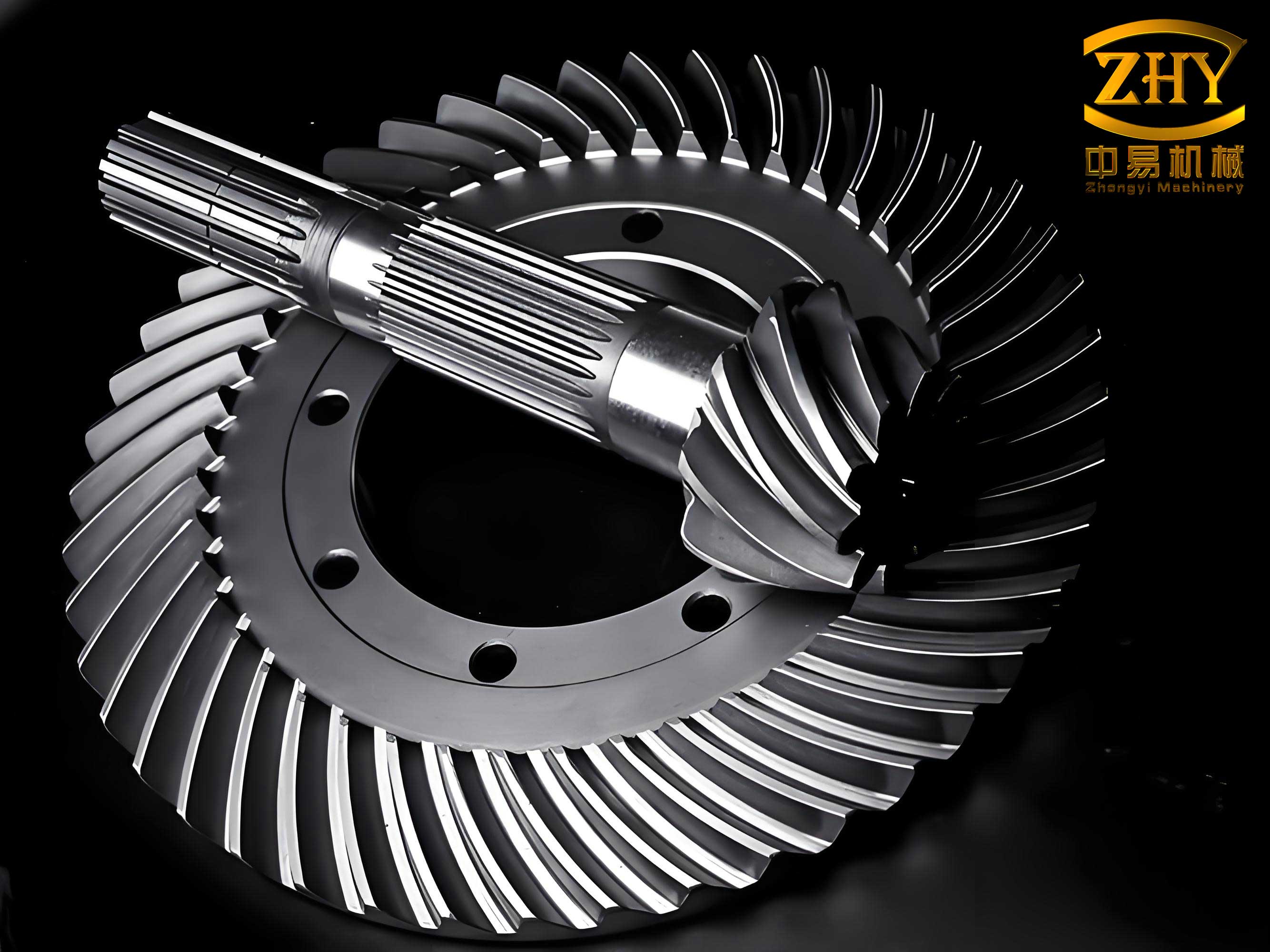
The image above illustrates the typical appearance of spiral bevel gears, showcasing their curved teeth that enable smooth and efficient power transmission. In our application, these gears were custom-designed to fit the existing crusher configuration. To understand the performance gains, we need to compute the total contact ratio for the spiral bevel gears, which includes both the transverse and face components. The calculations are more complex due to the spiral angle and tooth geometry, but they clearly demonstrate the superiority of spiral bevel gears.
First, we determine the pitch cone angles, which remain the same as for the straight bevel gears: δ1 ≈ 24.54° and δ2 ≈ 65.46°. The mean cone distance Rm is calculated from the outer cone distance R and tooth width b. Given R = 758.5 mm (derived from gear dimensions), we have:
$$ R_m = R – 0.5b = 758.5 – 0.5 \times 210 = 653.5 \text{ mm} $$
The mean diameters are:
$$ d_{m1} = d_1 \frac{R_m}{R} = m Z_1 \frac{R_m}{R} = 30 \times 21 \times \frac{653.5}{758.5} \approx 542.79 \text{ mm} $$
$$ d_{m2} = d_2 \frac{R_m}{R} = m Z_2 \frac{R_m}{R} = 30 \times 46 \times \frac{653.5}{758.5} \approx 1188.96 \text{ mm} $$
The virtual pitch diameters for the equivalent spur gears are:
$$ d_{v1} = \frac{d_{m1}}{\cos \delta_1} \approx \frac{542.79}{\cos 24.54^\circ} \approx 596.69 \text{ mm} $$
$$ d_{v2} = \frac{d_{m2}}{\cos \delta_2} \approx \frac{1188.96}{\cos 65.46^\circ} \approx 2862.7 \text{ mm} $$
The total addendum height h’ is given by h’ = 2ha* m = 2 × 0.85 × 30 = 51 mm. The addendum heights for the gear and pinion are computed using Gleason formulas:
$$ h_{a2} = m_t \left(0.46 + 0.39 \frac{Z_1 \cos \delta_2}{Z_2 \cos \delta_1}\right) $$
Where mt is the transverse module at the mean point. First, we find the mean transverse module:
$$ m_{mt} = m \frac{R_m}{R} = 30 \times \frac{653.5}{758.5} \approx 25.85 \text{ mm} $$
Then, ha2 ≈ 16.24 mm, and ha1 = h’ – ha2 ≈ 34.76 mm. The mean addendum heights are:
$$ h_{am1} = h_{a1} \frac{R_m}{R} \approx 34.76 \times \frac{653.5}{758.5} \approx 29.95 \text{ mm} $$
$$ h_{am2} = h_{a2} \frac{R_m}{R} \approx 16.24 \times \frac{653.5}{758.5} \approx 13.99 \text{ mm} $$
The virtual addendum diameters become:
$$ d_{va1} = d_{v1} + 2h_{am1} \approx 596.69 + 2 \times 29.95 \approx 656.59 \text{ mm} $$
$$ d_{va2} = d_{v2} + 2h_{am2} \approx 2862.7 + 2 \times 13.99 \approx 2890.68 \text{ mm} $$
The transverse pressure angle in the virtual gear is:
$$ \alpha_{vt} = \arctan\left(\frac{\tan \alpha_n}{\cos \beta}\right) = \arctan\left(\frac{\tan 20^\circ}{\cos 35^\circ}\right) \approx 23.96^\circ $$
Here, αn is the normal pressure angle (20°), and β is the spiral angle (35°). The base diameters are:
$$ d_{vb1} = d_{v1} \cos \alpha_{vt} \approx 596.69 \times \cos 23.96^\circ \approx 545.27 \text{ mm} $$
$$ d_{vb2} = d_{v2} \cos \alpha_{vt} \approx 2862.7 \times \cos 23.96^\circ \approx 2616.02 \text{ mm} $$
The center distance for the virtual gears is:
$$ a_v = 0.5(d_{v1} + d_{v2}) \approx 0.5(596.69 + 2862.7) \approx 1729.695 \text{ mm} $$
The length of path of contact gvα is calculated as:
$$ g_{v\alpha} = \frac{1}{2} \left[ \sqrt{d_{va1}^2 – d_{vb1}^2} + \sqrt{d_{va2}^2 – d_{vb2}^2} \right] – a_v \sin \alpha_{vt} $$
$$ g_{v\alpha} \approx \frac{1}{2} \left[ \sqrt{656.59^2 – 545.27^2} + \sqrt{2890.68^2 – 2616.02^2} \right] – 1729.695 \times \sin 23.96^\circ \approx 95.39 \text{ mm} $$
The base pitch pvb is:
$$ p_{vb} = \pi m_{mt} \cos \alpha_{vt} \approx \pi \times 25.85 \times \cos 23.96^\circ \approx 74.21 \text{ mm} $$
Thus, the transverse contact ratio is:
$$ \epsilon_{v\alpha} = \frac{g_{v\alpha}}{p_{vb}} \approx \frac{95.39}{74.21} \approx 1.29 $$
The face contact ratio, which accounts for the spiral angle, is:
$$ \epsilon_{v\beta} = \frac{b \tan \beta}{\pi m_{mt}} = \frac{210 \times \tan 35^\circ}{\pi \times 25.85} \approx 1.81 $$
Finally, the total contact ratio for the spiral bevel gears is the geometric sum of the two components:
$$ \epsilon_{v\gamma} = \sqrt{\epsilon_{v\alpha}^2 + \epsilon_{v\beta}^2} = \sqrt{1.29^2 + 1.81^2} \approx 2.22 $$
This total contact ratio of approximately 2.22 is a substantial improvement over the 1.728 of the straight bevel gears. It indicates that, on average, more than two teeth are in contact simultaneously, leading to smoother operation, reduced impact loads, and higher load-carrying capacity. The implementation of spiral bevel gears in our cone crushers has yielded remarkable benefits, which I will elaborate on in the following sections. The transition involved meticulous design and installation, but the long-term gains have justified the effort.
One of the key advantages of spiral bevel gears is their ability to distribute loads more evenly across the tooth surface. Unlike straight bevel gears, which suffer from edge loading due to misalignment, spiral bevel gears have a gradual engagement pattern that minimizes stress concentrations. This is particularly important in heavy-duty applications like cone crushers, where shock loads are common. The curved teeth of spiral bevel gears ensure that contact starts at one end and progresses across the face, providing a rolling motion that reduces friction and wear. Additionally, the higher contact ratio means that the load is shared among more teeth, lowering the contact pressure on individual teeth. This not only extends the gear life but also reduces the risk of tooth breakage, which was a frequent issue with straight bevel gears. In our experience, since switching to spiral bevel gears, we have observed a dramatic decrease in gear-related failures, with the gears lasting several years without replacement compared to the annual changes previously required.
Another significant benefit of spiral bevel gears is the reduction in noise and vibration. The gradual tooth engagement and higher contact ratio dampen impact forces, resulting in quieter operation. This is crucial in mining environments where noise pollution can be a concern. Moreover, the smooth transmission minimizes vibrations that can propagate through the crusher structure, potentially causing damage to other components such as bearings and shafts. In our Φ2.2M crushers, the use of spiral bevel gears has led to a noticeable decline in overall machine vibration, which in turn has improved the lifespan of associated parts like the copper bushings and eccentric assemblies. This holistic improvement underscores the value of upgrading to spiral bevel gears, as it enhances not just the gears themselves but the entire drivetrain system.
The manufacturability and maintainability of spiral bevel gears also offer advantages. While they are more complex to produce than straight bevel gears, modern manufacturing techniques, such as CNC grinding, allow for high precision and consistency. Gleason spiral bevel gears, in particular, can be lapped or ground after heat treatment to improve tooth surface finish, optimize contact patterns, and further reduce noise. This post-processing capability is a key feature that enables fine-tuning for specific applications. In our case, we utilized ground spiral bevel gears to ensure optimal performance in the harsh crushing environment. The ability to refine the gear teeth post-manufacture means that any minor deviations can be corrected, resulting in a more reliable and efficient gear set. This contrasts with straight bevel gears, which are typically not ground and thus more susceptible to inaccuracies that exacerbate operational issues.
From an economic perspective, the adoption of spiral bevel gears has proven cost-effective despite the higher initial investment. The reduced frequency of gear replacements, lower maintenance downtime, and decreased need for ancillary repairs translate to significant savings over the crusher’s lifespan. In our plant, the annual cost of replacing straight bevel gears, including labor and lost production time, was substantial. By contrast, the spiral bevel gears have operated reliably for over three years without major intervention, demonstrating their durability. This long service life not only cuts direct costs but also enhances production stability, ensuring that crushing targets are met consistently. Furthermore, the improved efficiency of spiral bevel gears can lead to energy savings, as smoother transmission reduces power losses due to friction and vibration. While quantifying these savings requires detailed monitoring, the overall operational benefits are clear.
To further illustrate the technical superiority of spiral bevel gears, let’s compare some key performance metrics between the two gear types in a tabular format. This comparison synthesizes the calculations and observations discussed earlier.
| Metric | Straight Bevel Gears | Spiral Bevel Gears |
|---|---|---|
| Contact Ratio (ε) | ≈1.728 | ≈2.22 |
| Tooth Contact Pattern | Line contact, prone to edge loading | Curved surface contact, gradual engagement |
| Load Distribution | Uneven, high stress concentrations | Even, reduced contact pressure |
| Noise and Vibration | High due to impact loads | Low due to smooth engagement |
| Transmission Efficiency | Lower (estimated 90-92%) | Higher (estimated 95-97%) |
| Expected Service Life | ~1 year in heavy-duty use | 3+ years with proper maintenance |
| Manufacturing Complexity | Relatively simple | Complex, requires precision grinding |
| Maintenance Requirements | Frequent inspections and replacements | Reduced, with periodic lapping possible |
The table highlights the multifaceted improvements offered by spiral bevel gears. The increased contact ratio is a fundamental factor driving these benefits, as it directly influences load capacity and smoothness. In engineering terms, the contact ratio can be expressed generally for gear systems, but for spiral bevel gears, it is enhanced by the spiral angle β. The face contact ratio component εvβ is particularly important, as it adds to the overall overlap. The formula for face contact ratio is derived from the geometry of helical teeth:
$$ \epsilon_{v\beta} = \frac{b \tan \beta}{\pi m_n} $$
Where mn is the normal module. In our case, with a spiral angle of 35°, this component contributes significantly to the total contact ratio. This design aspect is a key reason why spiral bevel gears outperform straight bevel gears in demanding applications.
In addition to the mechanical advantages, the use of spiral bevel gears aligns with broader trends in mining equipment toward higher reliability and automation. Modern cone crushers often incorporate advanced monitoring systems that track vibration, temperature, and load conditions. The stable operation provided by spiral bevel gears facilitates such monitoring, as fewer transient shocks and vibrations mean cleaner sensor data and more accurate diagnostics. This enables predictive maintenance strategies, where potential issues can be identified before they lead to failures. In our facility, we have integrated vibration sensors on the crushers with spiral bevel gears, and the data shows consistently lower amplitude peaks compared to historical data from straight bevel gear units. This not only improves safety but also optimizes maintenance schedules, reducing unplanned downtime.
The implementation process for spiral bevel gears in existing cone crushers requires careful planning. It is not merely a drop-in replacement; modifications to the housing, bearings, and lubrication system may be necessary to accommodate the different gear geometry and loading patterns. In our Φ2.2M crushers, we had to adjust the bearing clearances and upgrade the lubrication system to ensure adequate oil flow to the gear mesh. The installation also involved precise alignment using laser tools to avoid the misalignment issues that plagued the straight bevel gears. Post-installation, we conducted extensive testing under load to verify the contact pattern and make any final adjustments. This thorough approach ensured that the spiral bevel gears operated optimally from the start. The success of this project has served as a model for other upgrades in our plant, demonstrating that even older equipment can be revitalized with modern gear technology.
Looking ahead, the role of spiral bevel gears in cone crushers is likely to expand as manufacturers continue to push the boundaries of performance. Advances in materials science, such as the use of high-strength alloys and surface treatments, can further enhance the durability of spiral bevel gears. Additionally, digital twin simulations and finite element analysis allow for optimized tooth profiles that maximize contact ratio and minimize stress under specific operating conditions. These innovations will make spiral bevel gears even more attractive for heavy industrial applications. In my view, the transition to spiral bevel gears is not just a technical upgrade but a strategic investment in operational excellence. By embracing these advanced components, mining operations can achieve higher productivity, lower costs, and greater environmental sustainability through reduced energy consumption and waste.
In conclusion, the application of spiral bevel gears in cone crushers has proven to be a transformative improvement over traditional straight bevel gears. Through detailed analysis and practical implementation, I have demonstrated that spiral bevel gears offer a higher contact ratio, leading to smoother transmission, reduced noise and vibration, and increased load-carrying capacity. The calculations show a contact ratio increase from 1.728 to 2.22, which directly translates to better performance and longevity. The benefits extend beyond the gears themselves to the entire crusher system, including longer component life and lower maintenance requirements. While the initial cost and complexity are higher, the long-term savings and reliability gains justify the investment. As mining operations strive for greater efficiency and uptime, spiral bevel gears represent a key technology that can help achieve these goals. I am confident that their adoption will continue to grow, driven by the tangible results seen in plants like ours. The journey from problematic straight bevel gears to robust spiral bevel gears has been a rewarding one, highlighting the importance of innovation in industrial machinery.