
In the field of mechanical transmission, spiral bevel gears are fundamental components widely used in aerospace and other industries for motion transfer between intersecting or crossed axes. The performance of a spiral bevel gear pair is critically influenced by the tooth contact pattern, including its shape, size, and location. However, traditional manufacturing methods, such as the Gleason system, often lead to a detrimental phenomenon known as diagonal contact, particularly outer diagonal contact. This issue arises because these methods only ensure equal pressure angles at the calculated point on the tooth surface, causing pressure angle errors at other points due to spiral angle variations. As a result, the contact zone becomes diagonal, reducing meshing efficiency and load-carrying capacity, especially under heavy loads. To address this, we propose a novel machining approach called the spread-out helix modified roll method for spiral bevel gears. This method aims to eliminate diagonal contact fundamentally, thereby enhancing meshing performance and manufacturing efficiency.
The spread-out helix modified roll method builds upon existing techniques like the spiral forming method and the duplex helical method, but it offers broader applicability and simplicity. In this approach, the gear is processed using a generated method, while the pinion is machined with an additional helical feed motion. The key innovation lies in aligning the cutter axes parallel to each other during machining—specifically, the gear cutter axis is perpendicular to the gear root cone, and the pinion cutter axis is perpendicular to an equidistant surface of the gear root cone, i.e., the pinion face cone. This alignment ensures that the cutting surfaces of both cutters conform, allowing correct meshing along the pitch cone direction and theoretically eliminating diagonal contact. Moreover, by adjusting the normal curvatures in the lengthwise and profile directions of the tooth surface, we can control the contact area effectively. The lengthwise curvature is modified by changing the cutter tip radius, and the profile curvature is adjusted through modified roll (i.e., varying the generating ratio). Additionally, the geodesic torsion can be corrected to influence the contact path direction, provided no curvature interference occurs.
To elucidate the cutting principle of the spread-out helix modified roll method, we establish a mathematical model based on the relative motion and positional relationships among the machine tool, cutter, and workpiece. Using vector analysis, differential geometry, and gear meshing theory, we derive the machine-tool adjustment parameters with the tooth surface midpoint as the calculation point. The process involves two main steps: first, determining the gear’s adjustment parameters via the generated method, and second, computing the pinion’s parameters through indirect generation, which simplifies the derivation by assuming the cutter’s inner surface as an ideal thin surface that generates both gear and pinion tooth surfaces.
For the gear, generated machining is employed. The machine-tool adjustment parameters include radial setting \(S_2\), angular setting \(q_2\), machine installation angle \(\delta_{f2}\), axial work offset \(X_2\), sliding base setting \(X_{B2}\), and generating ratio \(i_{02}\). These are derived from the kinematics model. Let \(r_{02}\) be the nominal cutter radius, \(\beta\) the spiral angle, \(R_m\) the mean cone distance, \(\theta_{f2}\) the root angle, and \(\alpha_{02}\) the pressure angle. The radial setting \(S_2\) and angular setting \(q_2\) are calculated as follows:
First, a reference point \(M_2\) on the gear pitch cone is selected, leading to:
$$\tan q_2′ = \frac{r_{02} \cos \beta}{R_m \cos \theta_{f2} – r_{02} \sin \beta}, \quad S_2 = \frac{r_{02} \cos \beta}{\sin q_2′}.$$
To ensure the actual contact point \(P_2\) lies on the x-axis, the angular setting is adjusted:
$$q_2 = \arcsin\left(\frac{R_{P2} \cos \theta_2}{S_2}\right),$$
where \(R_{P2} = r_{02} – W_2 – l_2 \sin \alpha_{02}\), with \(W\) as the blade edge width and \(l_2\) as the tool conical surface parameter. For standard tooth design, \(X_2 = 0\) and \(X_{B2} = 0\). The generating ratio is given by \(i_{02} = \frac{\cos \theta_{f2}}{\sin \delta_2}\), where \(\delta_2\) is the gear pitch angle.
For the pinion, the spread-out helix modified roll method is used. The machine-tool adjustment parameters include radial setting \(S_1\), angular setting \(q_1\), axial work offset \(X_1\), sliding base setting \(X_{B1}\), generating ratio \(i_{01}\), second-order modified roll coefficient \(2c\), and helical feed parameter \(p\). The pinion tooth surface normal vector and curvature parameters are obtained indirectly from the gear cutter surface. At the calculation point \(P_1\), the normal vector \(\mathbf{n}_1\) in the pinion coordinate system is:
$$\begin{aligned}
n_{1x} &= \cos \alpha_{02} \cos \delta_{a1} \sin \theta_2 + \sin \alpha_{02} \sin \delta_{a1}, \\
n_{1y} &= \cos \alpha_{02} \cos \theta_2, \\
n_{1z} &= -\cos \alpha_{02} \sin \delta_{a1} \sin \theta_2 + \sin \alpha_{02} \cos \delta_{a1},
\end{aligned}$$
where \(\delta_{a1}\) is the pinion installation angle. The curvature parameters—normal curvatures \(A_1’\) and \(B_1’\) in the lengthwise and profile directions, and geodesic torsion \(C_1’\)—are derived from the induced curvature formulas:
$$\begin{aligned}
A_1′ &= -\Delta B_1′ \tan^2 \gamma’ – \frac{\cos \alpha_{02}}{R_{P2}}, \\
B_1′ &= -\Delta B_1′, \\
C_1′ &= \Delta B_1′ \tan \gamma’,
\end{aligned}$$
with \(\tan \gamma’ = \frac{\cos \alpha_{02} (\tan \alpha_{02} \sin \theta_2 – \tan \theta_{f2})}{\cos \theta_2}\) and \(\Delta B_1′ = -\frac{\cos \delta_{a1} \cos^2 \theta_2}{R_m \sin \delta_1 \cos \alpha_{02} (\tan \alpha_{02} – \tan \theta_{f2} \sin \theta_2)}\), where \(\delta_1\) is the pinion pitch angle. To achieve a desirable contact pattern, we apply small corrections \(\Delta A\), \(\Delta B\), and \(\Delta C\):
$$\begin{aligned}
A_1 &= A_1′ \pm \Delta A, \\
B_1 &= B_1′ \pm \Delta B, \\
C_1 &= C_1′ \pm \Delta C.
\end{aligned}$$
The pinion cutter surface is an Archimedes helicoid due to the helical feed motion, described by the vector equation:
$$\mathbf{r}_{01} = \begin{pmatrix} S_1 \cos q_1 + R_{P1} \sin \theta_1 \\ -S_1 \sin q_1 + R_{P1} \cos \theta_1 \\ -l_1 \cos \alpha_{01} + p \theta_1 \end{pmatrix},$$
where \(R_{P1} = r_{01} + l_1 \sin \alpha_{01}\), with \(r_{01}\) as the pinion cutter tip radius and \(l_1, \theta_1\) as parameters. The surface normal vector is:
$$\mathbf{n}_{01} = \frac{1}{\sqrt{R_{P1}^2 + (p \sin \alpha_{01})^2}} \begin{pmatrix} R_{P1} \cos \alpha_{01} \sin \theta_1 – p \sin \alpha_{01} \cos \theta_1 \\ R_{P1} \cos \alpha_{01} \cos \theta_1 + p \sin \alpha_{01} \sin \theta_1 \\ R_{P1} \sin \alpha_{01} \end{pmatrix}.$$
Using gear meshing theory, the pinion tooth surface is the conjugate of this cutter surface. The relative motion between the cutter and pinion involves angular velocities \(\omega_0 = \mathbf{z}\) (cutter) and \(\omega_1 = i_{01} \mathbf{x}_1\) (pinion), leading to relative angular velocity \(\omega_{01} = \omega_0 – \omega_1\) and relative velocity \(\mathbf{v}_{01} = \omega_{01} \times \mathbf{r}_{01} – \omega_1 \times \mathbf{r}\), where \(\mathbf{r}\) is the position vector of the pinion design crossing point. The meshing equation is \(\mathbf{v}_{01} \cdot \mathbf{n}_{01} = 0\). Combining coordinate transformations and curvature conditions, we obtain a system of equations for the adjustment parameters:
$$\begin{aligned}
\mathbf{r}_{01} &= \mathbf{M}_{01} \mathbf{r}_{p1} + \mathbf{r}, \\
\mathbf{n}_{01} &= \mathbf{M}_{01} \mathbf{n}_1, \\
\mathbf{v}_{01} \cdot \mathbf{n}_{01} &= 0, \\
k_1 &= \frac{A_1 B_1 – C_1^2}{B_1}, \\
\frac{1}{B_1} &= -\frac{(2c) \mathbf{v}_0 \cdot \mathbf{n}_{01} + (\omega_{01}, \mathbf{v}_0, \mathbf{n}_{01})}{(\omega_{01} \cdot \mathbf{e}_1)^2},
\end{aligned}$$
where \(k_1\) is the cutter surface normal curvature in the lengthwise direction, \(\mathbf{e}_1\) and \(\mathbf{e}_2\) are direction vectors, and \(\mathbf{v}_0\) is the cutter velocity. Solving this nonlinear system via numerical methods (e.g., MATLAB’s fsolve function) yields the pinion adjustment parameters: \(S_1, q_1, r_{01}, \theta_1, l_1, X_1, X_{B1}, i_{01}, 2c\).
To validate the spread-out helix modified roll method, we conducted virtual simulation and physical testing. A pair of spiral bevel gears was designed with basic parameters as shown in Table 1. These parameters are essential for defining the gear geometry and ensuring proper meshing. The spiral bevel gear pair consists of a right-hand gear and a left-hand pinion, typical for aerospace applications where high precision is required.
| Parameter | Pinion | Gear |
|---|---|---|
| Module (mm) | 4.112 | 4 |
| Number of Teeth | 9 | 37 |
| Pressure Angle (°) | 20 | 20 |
| Spiral Angle (°) | 35 | 35 |
| Face Width (mm) | 24 | 24 |
| Whole Depth Coefficient | 1.832 | 1.832 |
| Working Depth Coefficient | 1.650 | 1.650 |
| Pitch Angle (°) | 13.6713 | 76.3287 |
| Face Angle (°) | 17.7987 | 78.2542 |
| Root Angle (°) | 11.7458 | 72.2013 |
| Hand of Spiral | Left | Right |
Using these parameters, we computed the machine-tool adjustment parameters for both gear and pinion, as summarized in Table 2. These values are critical for setting up the CNC gear milling machine accurately. The gear is machined with generated method parameters, while the pinion uses the spread-out helix modified roll parameters, including the helical feed parameter \(p\) and second-order modified roll coefficient \(2c\).
| Adjustment Parameter | Pinion (Concave Side) | Gear (Convex Side) |
|---|---|---|
| Cutter Diameter (mm) | 157.1152 | 150.7729 |
| Radial Setting (mm) | 67.9110 | 66.3235 |
| Angular Setting (°) | 71.5114 | 67.4435 |
| Axial Work Offset (mm) | 1.9726 | 0 |
| Sliding Base Setting (mm) | -7.6148 | 0 |
| Installation Angle (°) | 17.7987 | 72.2013 |
| Generating Ratio | 4.3399 | 1.0265 |
| Second-Order Modified Roll Coefficient | 0.0126 | 0 |
| Helical Feed Parameter (mm/rad) | 7.8975 | 0 |
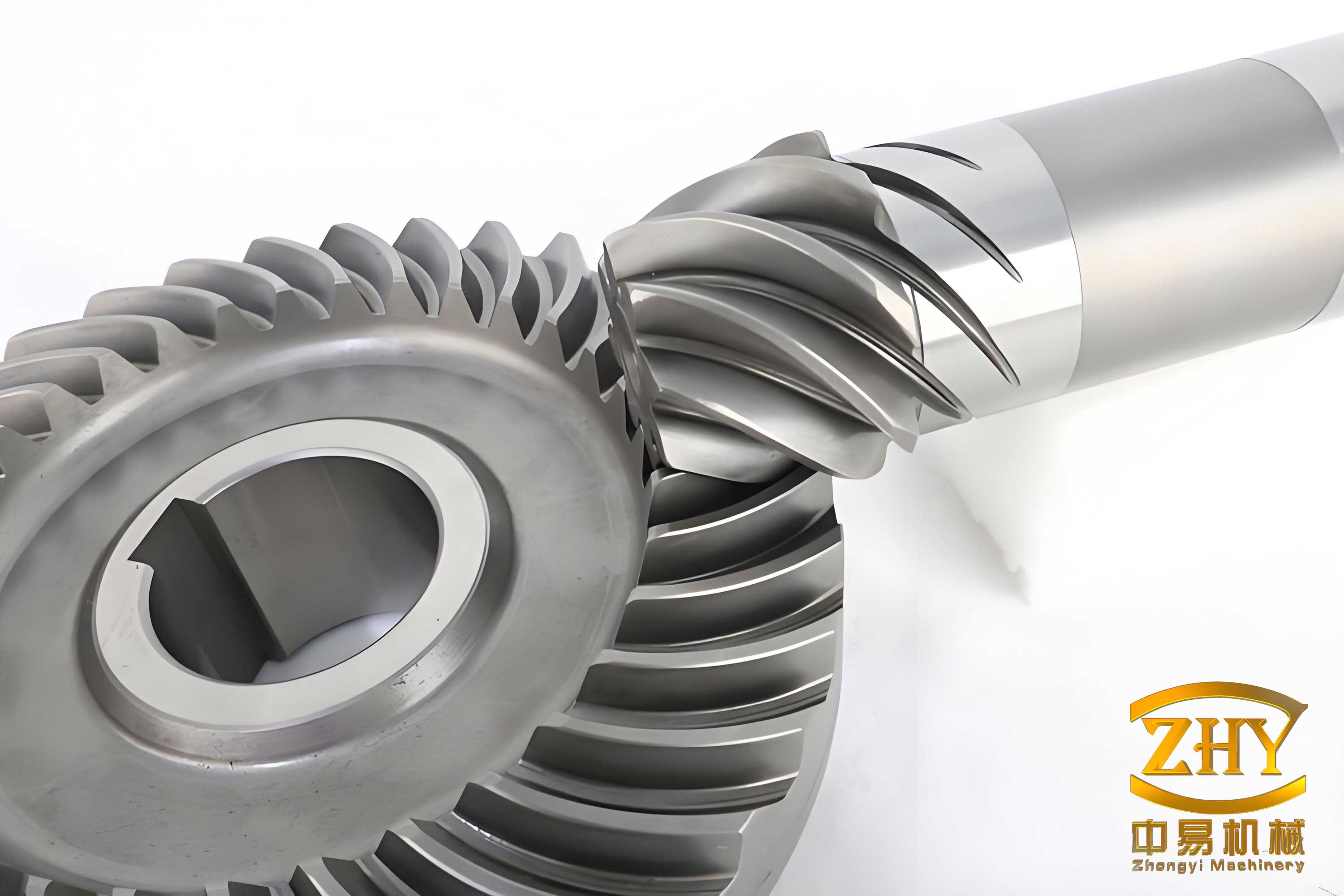
With these parameters, we developed a three-dimensional virtual simulation model using Creo software. The machining process was discretized, simulating the cutter’s movement relative to the gear blank through Boolean operations. The cutter was modeled as a dual-sided blade generating a conical surface, and the gear blank was designed parametrically. After machining, the tooth surface was reconstructed from key points to ensure smoothness, resulting in accurate spiral bevel gear models. The virtual model of the spiral bevel gear pair is depicted below, showcasing the complex geometry inherent in these components.
We performed tooth contact analysis (TCA) on the virtual models to assess the contact pattern. The gear pair was assembled with proper alignment, and dynamic interference detection was conducted. The instantaneous contact zone appeared elliptical and slightly inclined relative to the root cone line. For comparison, we also generated a gear pair using the traditional Gleason SGM method. The TCA results, as shown in Figure 1, indicate that the spread-out helix modified roll method produces a contact trajectory nearly perpendicular to the root cone line, effectively eliminating diagonal contact. In contrast, the SGM method exhibits pronounced diagonal contact, which can lead to poor meshing performance.
To further validate our approach, we conducted physical cutting experiments on a CNC gear milling machine using the derived adjustment parameters. The manufactured spiral bevel gears were then installed on a rolling tester with specified mounting distances. The tooth contact pattern obtained from the rolling test is shown in Figure 2. The contact zone is oval-shaped and centrally located, with minimal diagonal orientation, closely matching the simulation results. This confirms the practical effectiveness of the spread-out helix modified roll method in eliminating diagonal contact and improving meshing quality.
The spread-out helix modified roll method offers significant advantages for spiral bevel gear manufacturing. By aligning cutter axes parallelly and incorporating helical feed motion, it addresses the inherent limitations of traditional methods that cause diagonal contact. The mathematical model provides a systematic way to compute machine-tool adjustment parameters, enabling precise control over tooth surface geometry. Virtual simulations and physical tests demonstrate that this method can produce spiral bevel gears with optimal contact patterns, enhancing transmission efficiency and durability. Future work could explore applications in high-speed or heavy-load scenarios, as well as integration with advanced CNC systems for automated adjustment. Overall, the spread-out helix modified roll method represents a promising advancement in spiral bevel gear technology, contributing to more reliable and efficient mechanical transmissions.
In conclusion, our research on spiral bevel gears has led to the development of the spread-out helix modified roll method, which effectively eliminates diagonal contact. The derivation of machine-tool parameters, supported by simulation and experimental validation, underscores its practicality. As spiral bevel gears continue to be vital in aerospace and industrial applications, such innovations are crucial for achieving higher performance and reducing manufacturing costs. We believe this method will find widespread adoption in gear production, paving the way for next-generation transmission systems.