
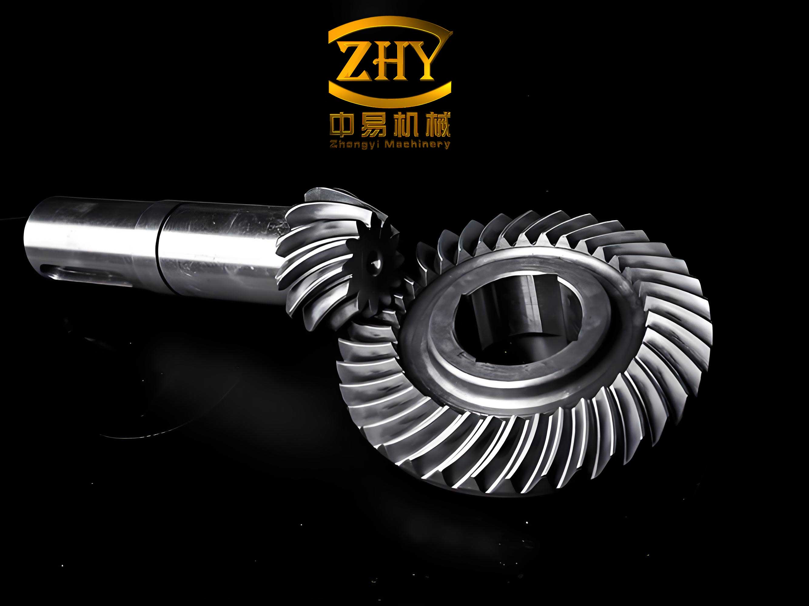
The pursuit of higher performance and reliability in modern aerospace propulsion systems has led to the widespread adoption of advanced design features, one of the most significant being the implementation of elastic supports for rotor systems. These supports are engineered to mitigate vibration levels and manage dynamic loads effectively. However, this design advancement introduces a complex interaction between the rotor dynamics and the performance of critical power transmission components, most notably the main transmission spiral bevel gear pairs. The inherent flexibility of the supporting structure allows for larger elastic deformations of the rotor shafts during operation, induced by forces such as mass unbalance, gyroscopic effects, and the meshing forces of the gears themselves. These deformations inevitably alter the relative positional alignment of the mating spiral bevel gear pair, deviating from their theoretically ideal installation settings. Such misalignments can drastically degrade contact performance, leading to phenomena like edge contact, localized stress concentrations, increased transmission error, and ultimately, reduced gear life and system reliability. Therefore, a comprehensive understanding of the actual tooth contact behavior of spiral bevel gears within elastically supported rotor systems is not merely an academic exercise but a critical engineering necessity for ensuring operational stability and durability.
This article presents an integrated theoretical and experimental study focused on unraveling the contact characteristics of spiral bevel gears operating under the influence of elastic supports. The core objective is to quantify how shaft deformations, resulting from the dynamic response of a rotor system, translate into changes in gear mesh alignment and subsequently affect the contact pattern and motion transmission accuracy. The methodology involves a two-pronged approach: first, a detailed dynamic analysis of the rotor system to compute the specific deformations at the gear mounting locations; and second, the application of advanced tooth contact analysis (TCA) techniques that incorporate these computed deformations as equivalent misalignments. The theoretical predictions are then rigorously validated against experimental data obtained from a specially designed test rig that simulates the elastic support conditions of an aero-engine rotor system. The findings from both streams of investigation converge to highlight the profound impact that support stiffness has on the functional performance of spiral bevel gear transmissions.
Theoretical Framework: Integrating Rotor Dynamics with Gear Mesh Analysis
The accurate prediction of spiral bevel gear contact behavior under elastic supports requires a coupled analysis that bridges rotor dynamics and gear geometry. The process begins with modeling and analyzing the complete rotor system to extract the deformations at the precise points where the pinion and gear are mounted.
Rotor System Deformation Analysis
The rotor system, which includes the engine rotor, a quill shaft, and the driven gear shaft, is subjected to a complex set of dynamic forces during operation. To analyze its steady-state response, a lumped-mass model is typically employed. This model discretizes the continuous rotor into a series of concentrated masses and massless elastic shaft segments. For the system under investigation, a three-line model is constructed, representing the main rotor line, the quill shaft line, and the driven gear shaft line. A transfer matrix method is particularly effective for performing a coupled bending-torsion steady-state response analysis on such multi-line rotor systems with elastic supports. This method systematically calculates the state vectors (containing displacement, slope, bending moment, shear force, etc.) from one station to the next, applying compatibility and equilibrium conditions at junctions and supports.
The key outputs from this dynamic analysis are the complex deformations at the nodes corresponding to the pinion and gear mounting locations. These deformations are expressed in a local coordinate system attached to each gear. For a spiral bevel gear, a meaningful local coordinate system $\Sigma_1$ (for the pinion) and $\Sigma_2$ (for the gear) is defined with its origin at the mean cone distance point (the pitch point), as follows:
- $x$-axis: Directed from the origin towards the instantaneous contact point (or along the line of action).
- $z$-axis: Directed along the gear axis, pointing towards the gear’s back face (large end).
- $y$-axis: Determined by the right-hand rule, completing the orthogonal coordinate system.
In these coordinates, the computed deformations include:
$$ \mathbf{\delta_{node}} = \{ \phi, f_x, f_y, f_z, \theta_x, \theta_y \}^T $$
where $\phi$ is the torsional rotation (twist), $f_x, f_y, f_z$ are translational displacements, and $\theta_x, \theta_y$ are rotational displacements (slopes) about the respective axes. A sample of such calculated deformations at two different rotational speeds for a specific rotor configuration is summarized in the table below. The support stiffness values used in this example are $K_{front} = 1.57 \times 10^8 \text{ N/m}$ (relatively rigid) and $K_{rear} = 0.15 \times 10^8 \text{ N/m}$ (elastic), with a transmitted power of 150 kW.
| Speed (rpm) | Node | $\phi$ (rad) | $f_x$ (mm) | $f_y$ (mm) | $f_z$ (mm) | $\theta_x$ (rad) | $\theta_y$ (rad) |
|---|---|---|---|---|---|---|---|
| 27408 | Pinion (58) | $0.922 \times 10^{-3}$ | 0.1736 | $0.291 \times 10^{-1}$ | $0.207 \times 10^{-1}$ | $0.263 \times 10^{-3}$ | $0.121 \times 10^{-2}$ |
| 27408 | Gear (75) | $0.269 \times 10^{-2}$ | $0.385 \times 10^{-1}$ | $0.299 \times 10^{-1}$ | $0.776 \times 10^{-1}$ | $0.112 \times 10^{-2}$ | $0.121 \times 10^{-2}$ |
| 97392 | Pinion (58) | $0.386 \times 10^{-2}$ | $0.189 \times 10^{-1}$ | $0.111 \times 10^{-1}$ | $0.175 \times 10^{-2}$ | $0.223 \times 10^{-4}$ | $0.441 \times 10^{-4}$ |
| 97392 | Gear (75) | 0.597 | $0.116 \times 10^{-1}$ | $0.903 \times 10^{-2}$ | $0.247 \times 10^{-1}$ | $0.351 \times 10^{-3}$ | $0.351 \times 10^{-3}$ |
Tooth Contact Analysis (TCA) with Equivalent Misalignments
The second phase of the theoretical investigation involves performing a detailed Tooth Contact Analysis (TCA). The foundation of TCA lies in mathematically modeling the tooth surfaces of the spiral bevel gear pair based on their manufacturing process (e.g., using a face-milling or face-hobbing method). Coordinate systems are established for the cutting process: $\Sigma_l = \{O_l, i_l, j_l, k_l\}$ for the gear and $\Sigma_r = \{O_r, i_r, j_r, k_r\}$ for the pinion, where the origins lie on the cradle axis, and the $k$-axes are along this cradle axis.
The tooth surface points are defined by two independent parameters: the cradle rotational angle $q$ (or its equivalent machine settings) and an angular parameter $\theta$ defining a point on the generating surface. Through the kinematics of the gear generation process, the position vector of any point on the pinion and gear tooth surfaces can be derived as:
$$ \mathbf{R}_r = \mathbf{R}_r(q_r, \theta_r), \quad \mathbf{R}_l = \mathbf{R}_l(q_l, \theta_l) $$
For a pair of perfectly aligned gears, the pinion coordinate system $\Sigma_r$ is positioned within the gear coordinate system $\Sigma_l$ according to the theoretical mounting distances: the pinion axial offset $H_0$, the gear axial offset $J_0$, and the vertical offset $V_0$ (which defines the shaft angle). The condition for contact at any instant is that a point on the pinion surface coincides with a point on the gear surface, and their surface normals are collinear at that point. This leads to a system of equations that can be solved for the contact path. For the initial, unloaded alignment, these equations can be conceptually represented as:
$$ \begin{cases}
F_1(\theta_r, q_r, \theta_l, q_l) = H_0 \\
F_2(\theta_r, q_r, \theta_l, q_l) = J_0 \\
F_3(\theta_r, q_r, \theta_l, q_l) = V_0
\end{cases} $$
Solving this system yields the transmission error $\Delta \phi_2(\phi_1)$ and the unloaded contact pattern.
The critical innovation for analyzing spiral bevel gears in elastic supports is to incorporate the rotor deformations as equivalent changes to these mounting dimensions. The local deformation coordinates from the rotor analysis ($\Sigma_1, \Sigma_2$) must be transformed into the global TCA mounting coordinate system $\Sigma = \{O, H, J, V\}$, where $H$, $J$, and $V$ axes correspond to the pinion axis, gear axis, and the perpendicular direction to the plane containing both axes, respectively. The shaft angle is denoted by $\sigma$. The equivalent misalignments $\Delta H, \Delta J, \Delta V, \Delta \sigma$ are calculated as follows:
$$
\begin{aligned}
\Delta H &= f_{z1} – f_{x2}\sin\sigma – f_{z2}\cos\sigma \\
\Delta J &= -f_{x1}\sin\sigma – f_{z2} – f_{z1}\cos\sigma \\
\Delta V &= -f_{y1} – f_{y2} – r_1\phi_1 – r_2\phi_2 – L_1\theta_{x1} + L_2\theta_{x2} \\
\Delta \sigma &= \theta_{y1} + \theta_{y2}
\end{aligned}
$$
Here, $L_1$ and $L_2$ are the axial distances from the pitch cone apex to the mean cone distance point for the pinion and gear, respectively, and $r_1$, $r_2$ are the mean pitch radii. The terms $f_{x1}, \phi_1$, etc., refer to the deformation components of the pinion node (from $\Sigma_1$), and $f_{x2}, \phi_2$, etc., refer to those of the gear node (from $\Sigma_2$).
The TCA equations are then modified by replacing the nominal mounting values with their perturbed counterparts:
$$ \begin{cases}
F_1(\theta_r, q_r, \theta_l, q_l) = H_0 + \Delta H \\
F_2(\theta_r, q_r, \theta_l, q_l) = J_0 + \Delta J \\
F_3(\theta_r, q_r, \theta_l, q_l) = V_0 + \Delta V
\end{cases} $$
Furthermore, during the coordinate transformation of the pinion surface into the gear coordinate system, the actual shaft angle becomes $\sigma + \Delta\sigma$. Solving this modified system provides the contact pattern and transmission error for the spiral bevel gear pair under the specific elastic support conditions and loading that produced the deformations $\Delta H, \Delta J, \Delta V, \Delta \sigma$. The size of the instantaneous contact ellipse is further determined by considering the local surface curvatures and an assumed normal load or approach distance.
Experimental Methodology for Contact Performance Validation
To validate the theoretical predictions, an experimental study was conducted using a rotor test facility designed to simulate the elastic support conditions of an aero-engine. The primary goal was to physically observe the changes in contact pattern and measure the transmission error of a spiral bevel gear pair under varying support stiffness and load conditions.
Based on the principle of dynamic equivalence, the complex three-line engine rotor was simulated using a simplified, single-disc, two-bearing rotor system. This simplification maintains the critical dynamic characteristics relevant to gear misalignment at the intended operating speeds. The pinion (active spiral bevel gear) was mounted at the output end of this rotor. The support stiffness was made adjustable by using “squirrel-cage” elastic rings in the bearing housings, allowing for tests under both “rigid” (high stiffness) and “elastic” (low stiffness) support configurations.
The test setup consisted of a speed-controlled DC drive motor connected to the rotor input shaft via a flexible coupling. A DC generator attached to the output side of the gearbox served as the load absorption unit, enabling power to be transmitted through the spiral bevel gear pair under test. The test gears had the following key geometrical parameters, representative of aerospace applications:
| Parameter | Symbol | Value |
|---|---|---|
| Module | $m$ | 4 mm |
| Pressure Angle | $\alpha$ | 20° |
| Mean Spiral Angle | $\beta$ | 35° |
| Number of Teeth (Pinion/Gear) | $Z_1 / Z_2$ | 18 / 28 |
| Profile Shift Coefficient | $x_1 / x_2$ | +0.2275 / -0.2275 |
| Accuracy Grade | – | AGMA 12 |
| Material | – | Case-hardened Alloy Steel |
Contact Pattern Recording: The static and dynamic contact patterns were recorded using the bearing blue (prussian blue) method. A thin, uniform layer of marking compound was applied to the pinion teeth. The gearbox was then run under specific speed and load conditions for a short period. The transfer of the compound from the pinion to the gear teeth created a visible imprint of the contact area. This imprint was preserved by carefully applying transparent adhesive tape over the marked gear teeth and then lifting the tape, which captured a precise replica of the contact pattern for analysis and comparison with theoretical predictions.
Transmission Error Measurement: The transmission error (TE), defined as the deviation of the gear’s actual angular position from its theoretical position relative to the pinion, was measured directly. High-precision magnetic disk encoders were mounted on both the input (pinion) shaft and the output (gear) shaft. The sinusoidal signals from these encoders were processed through a phase-comparison circuit. One signal was used as a reference, and the other was digitally divided to account for the gear ratio. The phase difference between the two processed signals is directly proportional to the instantaneous transmission error. This analog error signal was recorded in real-time using an X-Y plotter, providing a continuous plot of transmission error over one or multiple mesh cycles.
Analysis and Discussion of Results
The combined theoretical and experimental approach yielded consistent and insightful results regarding the behavior of spiral bevel gears in elastic support environments. The comparison focused on four distinct operational states: light load with rigid supports, heavy load with rigid supports, light load with elastic supports, and heavy load with elastic supports.
1. Baseline Performance (Rigid Supports, Light Load): Both the TCA simulation and the initial experimental setup under nearly rigid, lightly loaded conditions showed an excellent contact pattern. The elliptical contact area was centrally located on the gear tooth flank, slightly biased towards the heel (large end) and the center of the profile. The corresponding transmission error curve exhibited a low amplitude and a smooth, predominantly linear character. This confirmed that the basic gear design and manufacturing parameters were sound and capable of providing good meshing performance under ideal, aligned conditions. The experimental pattern served as the validated baseline for subsequent comparisons.
2. Effect of Increased Load under Rigid Supports: As the transmitted torque increased while maintaining rigid supports, predictable changes occurred. The contact ellipse grew in size due to increased elastic deformation of the tooth surfaces under load. Furthermore, the contact patch migrated towards the heel (large end) of the tooth. This is a classic response to load-induced deflections, which effectively increases the misalignment. The transmission error amplitude also increased, and its waveform showed more pronounced nonlinearities. These results, observed both in analysis and experiment, are well-understood behaviors for spiral bevel gears and validated the fundamental accuracy of the TCA methodology and the test rig’s loading capability.
3. Critical Impact of Elastic Supports (Light Load): Introducing elastic supports, even under light loads, produced a dramatic shift in contact behavior compared to the rigid support baseline. The theoretical model, incorporating the equivalent misalignments from the rotor’s static or low-speed dynamic response, predicted a significant movement of the contact ellipse. The patch shifted towards the toe (small end) and the top (tip) of the gear tooth. Experimentally, this was clearly observed: the bearing blue imprint moved sharply to the toe and tip region, confirming the model’s prediction. The transmission error under these conditions also changed, showing a different slope and parabolic content compared to the rigid support case. This demonstrates that the static or low-frequency deformation of the shaft system due to support flexibility alone is sufficient to severely misalign the spiral bevel gear mesh, leading to a non-optimal contact condition that predisposes the gear to stress concentrations at the edges.
4. Combined Effect of Elastic Supports and Heavy Load: The most critical condition arises under the combination of elastic supports and high operational load. The TCA results for this scenario indicated an exacerbation of the trends seen under light elastic support. The contact ellipse, already biased towards the toe-top, now enlarged and moved further towards the extreme edge of the tooth. The experimental contact pattern vividly confirmed this, showing a large, elongated patch threatening to run off the edge at the toe. The transmission error magnitude increased substantially, and its waveform became highly irregular, indicating potential loss of contact, impacts, and severe vibratory excitation. This state represents a high-risk scenario for spiral bevel gear failure, where edge contact can lead to rapid pitting, scoring, or tooth fracture.
The following table summarizes the qualitative trends observed from both the theoretical and experimental investigations:
| Support Condition | Load Condition | Contact Pattern Trend | Transmission Error Trend | Risk Level |
|---|---|---|---|---|
| Rigid | Light | Central, slightly heel-side | Low amplitude, smooth | Low |
| Rigid | Heavy | Larger, moves towards heel | Amplitude increases | Medium |
| Elastic | Light | Moves towards toe and tip | Changed form, higher nonlinearity | Medium-High |
| Elastic | Heavy | Large, moves to extreme toe/top, edge contact likely | High amplitude, irregular | Very High |
The agreement between the theoretical TCA predictions (which used the calculated $\Delta H, \Delta J, \Delta V, \Delta \sigma$) and the experimental measurements is remarkably strong. This validates the core premise of the study: that rotor deformations can be accurately mapped to equivalent gear misalignments, and that these misalignments are the primary driver behind the altered contact characteristics of spiral bevel gears in flexible rotor systems. The results underscore that the support stiffness is not merely a parameter for controlling global rotor vibration but is a first-order design variable that directly governs the meshing quality and functional performance of the power transmission spiral bevel gears.
Conclusions and Design Implications
This integrated theoretical and experimental investigation into the contact characteristics of spiral bevel gears operating within elastically supported rotor systems leads to several definitive conclusions and important design guidelines:
- Dominant Influence of Support Stiffness: The stiffness of the rotor supports has a profound and direct impact on the contact pattern and transmission error of the main transmission spiral bevel gear pair. It is a critical design parameter that must be considered concurrently with rotor dynamics and gear design. Optimizing support stiffness is essential for achieving acceptable spiral bevel gear meshing performance.
- Mechanism of Performance Degradation: Under elastic supports, shaft deformations induced by static loads and dynamic rotor responses are transformed into equivalent misalignments (changes in axial settings $H, J$, offset $V$, and shaft angle $\sigma$). These misalignments disrupt the carefully engineered conjugate action of the spiral bevel gear teeth, causing the contact pattern to migrate from its optimal central location. The characteristic migration is towards the toe and tip of the tooth under typical bending deformations.
- Risk of Edge Contact and Instability: The combination of elastic supports and high operational load presents the worst-case scenario. It drives the contact patch to the extreme edges of the tooth (toe/top), significantly increases transmission error amplitude, and introduces high nonlinearities into the error function. This condition severely increases the risk of destructive edge contact, elevated dynamic loads, noise, and premature gear failure, thereby threatening the transmission’s reliability.
- Design Paradigm Shift: The design process for advanced rotor systems employing spiral bevel gears must evolve from a sequential approach to a fully integrated one. The selection of support stiffness should be a multi-objective optimization problem balancing: a) rotor critical speed placement and unbalance response, b) stability margins, and c) spiral bevel gear contact performance under all anticipated load conditions. Analytical tools combining rotor dynamics and advanced TCA, as demonstrated here, are indispensable for this task.
- Validation and Predictive Capability: The methodology of coupling rotor deformation analysis with TCA via equivalent misalignments has been experimentally validated. It provides a reliable predictive tool for assessing the contact performance of spiral bevel gears in the design phase, allowing engineers to proactively identify potential issues and refine support and gear design parameters before hardware is built.
In summary, ensuring the reliable operation of high-performance spiral bevel gear transmissions in modern aero-engines requires a holistic view that explicitly accounts for the flexibility of the structural support system. The contact characteristics of the spiral bevel gear are inextricably linked to the dynamic behavior of the rotor it is mounted on. By understanding and modeling this link, designers can make informed decisions that enhance both the dynamic smoothness and the mechanical integrity of the entire propulsion system.