
In the field of mechanical engineering, the study of dynamic behavior in gear systems is crucial for enhancing performance and reliability. Spiral bevel gears, widely used in applications such as helicopters, automobiles, and construction machinery, transmit motion and power between intersecting shafts. As operational speeds and loads increase, issues related to strength, vibration, and noise become critical bottlenecks affecting product quality. Therefore, understanding the dynamic characteristics of spiral bevel gears has garnered significant attention from researchers worldwide. Although prior studies have explored structural modes, vibrations, and dynamic experiments, there remains a gap in comprehensive theoretical and experimental validation, particularly when considering factors like mesh stiffness, transmission error, and meshing impact simultaneously. This article aims to address this by developing a detailed dynamic model that incorporates these key meshing characteristics, providing insights into vibration reduction strategies for spiral bevel gears.
We begin by emphasizing the importance of spiral bevel gears in high-performance systems. Their complex geometry, involving curved teeth and intersecting axes, introduces unique challenges in dynamic analysis. Vibration in spiral bevel gears not only affects noise levels but also influences fatigue life and operational stability. Previous research has often simplified the modeling of mesh stiffness and impact forces, leading to potential inaccuracies in predicting dynamic responses. For instance, some studies used approximate formulas for impact forces, while others focused solely on stiffness variations. However, a holistic approach that integrates both stiffness excitation and meshing impact, along with considerations of design parameters like transmission error and contact ratio, is essential for accurate dynamic analysis. In this work, we build upon existing methodologies by incorporating results from loaded tooth contact analysis (LTCA) and tooth contact analysis (TCA) to compute time-varying mesh stiffness and meshing impact excitation more precisely.
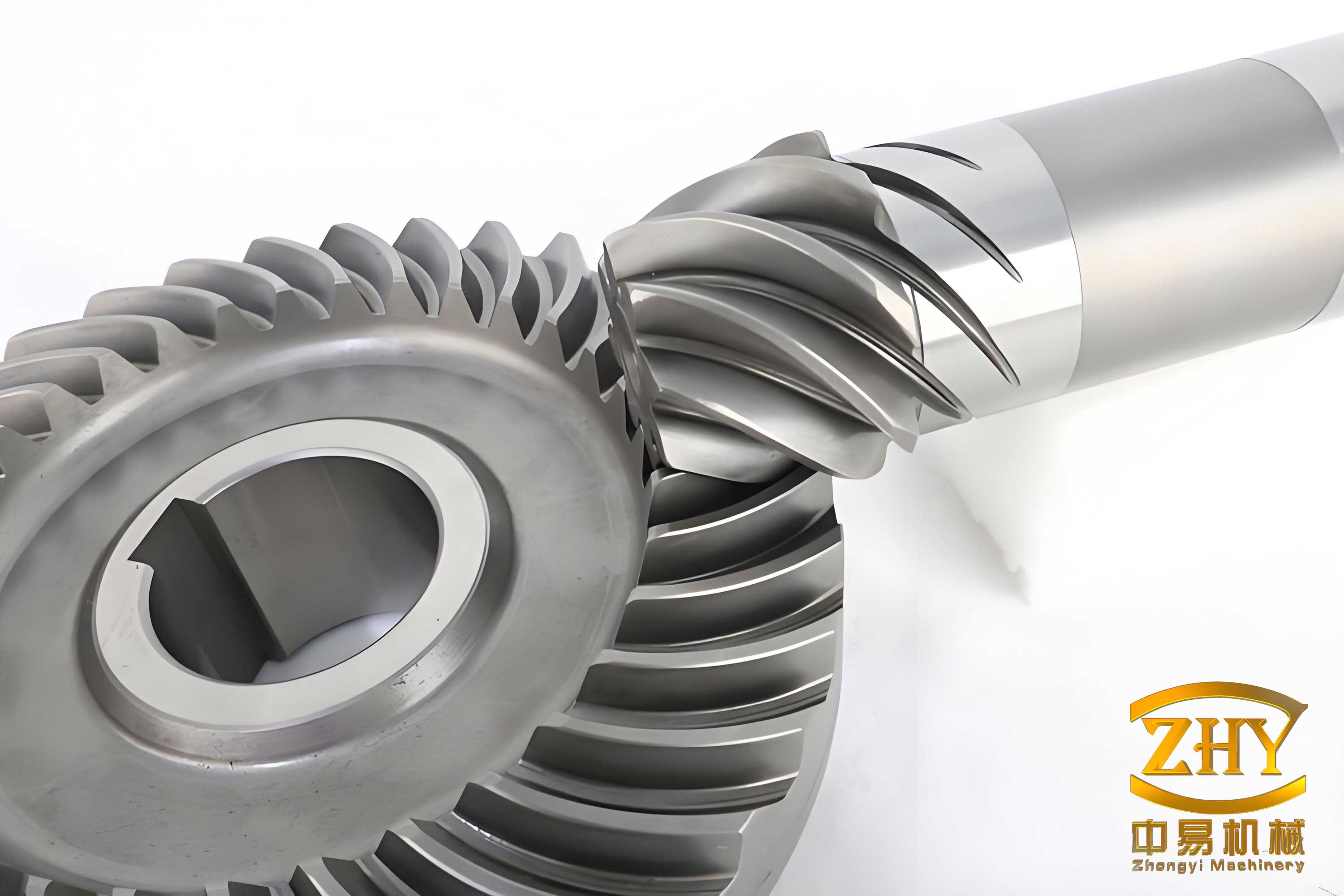
The dynamic behavior of spiral bevel gears is influenced by multiple factors, including geometric design, material properties, and operating conditions. Key among these are the mesh stiffness, which varies during the engagement cycle due to changing contact conditions, and the meshing impact that occurs when teeth first come into contact. These excitations can lead to significant vibrations, especially at high speeds. To analyze this, we first establish a concentrated parameter model for the spiral bevel gear pair. This model considers bending, torsion, and axial vibrations, resulting in an eight-degree-of-freedom (8-DOF) system. The equations of motion are derived based on Newton’s second law, accounting for the forces along three coordinate directions and the torsional effects. We then non-dimensionalize these equations to eliminate rigid body displacement and normalize scales, facilitating numerical solution.
The mesh stiffness excitation is computed using loaded tooth contact analysis. This involves determining the contact forces and deformations at discrete points along the mesh cycle, from which the time-varying mesh stiffness can be derived. The stiffness values are approximated as a periodic function using Fourier series expansion. For meshing impact excitation, we combine tooth contact analysis, load distribution coefficients, and an impact model. The initial meshing point is identified from the load-sharing curve, and the impact force is calculated based on the relative velocity at engagement, gear geometry, and stiffness. This approach provides a more accurate representation of the impulsive forces that contribute to vibration.
To solve the dynamic equations, we employ a variable-step fourth-order Runge-Kutta method. This numerical technique is suitable for handling the nonlinearities and time-varying parameters in the system. The dynamic responses, including displacements, velocities, and accelerations, are obtained for various operating conditions. We analyze the effects of transmission error amplitude and design contact ratio on vibration levels, as these are critical design parameters for spiral bevel gears. The results demonstrate that increased transmission error leads to higher vibrations, while a higher design contact ratio can reduce vibration, highlighting the importance of optimal gear design.
In the following sections, we detail the dynamic modeling process, excitation calculations, numerical solution, and case study analysis. We present formulas and tables to summarize key concepts and results, ensuring a comprehensive understanding of spiral bevel gear dynamics. The insights gained from this study can guide engineers in designing quieter and more reliable spiral bevel gear systems for demanding applications.
Dynamic Modeling of Spiral Bevel Gears
The dynamic model for a spiral bevel gear pair is developed using a concentrated parameter approach. We consider a three-dimensional coordinate system with the intersection point of the gear axes as the origin. The pinion axis is aligned with the X-axis, and the gear axis with the Y-axis. The system accounts for vibrations along the X, Y, and Z directions, as well as torsional vibrations, leading to eight degrees of freedom. The displacement vector is represented as $$\{X_1, Y_1, Z_1, \theta_1, X_2, Y_2, Z_2, \theta_2\}^T$$, where subscripts 1 and 2 denote the pinion and gear, respectively.
The mesh force between the spiral bevel gears has normal and component directions. The normal mesh force $$F_n$$ is expressed as:
$$F_n = k_n(t) \lambda_n + c_n \dot{\lambda}_n$$
Here, $$k_n(t)$$ is the time-varying mesh stiffness, $$c_n$$ is the damping coefficient, and $$\lambda_n$$ is the relative displacement along the mesh normal direction. The component forces along the X, Y, and Z axes are given by:
$$F_x = -F_n (\sin\alpha_n \cos\delta_2 + \cos\alpha_n \sin\beta_2 \sin\delta_2)$$
$$F_y = F_n (\sin\alpha_n \sin\delta_2 \pm \cos\alpha_n \sin\beta_2 \cos\delta_2)$$
$$F_z = \pm F_n \cos\alpha_n \cos\beta_2$$
where $$\alpha_n$$ is the normal pressure angle, $$\beta_2$$ is the spiral angle of the gear, $$\delta_2$$ is the pitch angle, and the signs depend on the hand of the spiral (positive for left-hand, negative for right-hand). For simplicity, we define coefficients:
$$a_1 = -(\sin\alpha_n \cos\delta_2 + \cos\alpha_n \sin\beta_2 \sin\delta_2)$$
$$a_2 = \sin\alpha_n \sin\delta_2 \pm \cos\alpha_n \sin\beta_2 \cos\delta_2$$
$$a_3 = \pm \cos\alpha_n \cos\beta_2$$
The relative displacement $$\lambda_n$$ combines translational and torsional vibrations, along with static transmission error:
$$\lambda_n = a_1 (X_1 – X_2) + a_2 (Y_1 – Y_2) + a_3 (Z_1 – Z_2) + r_1 \theta_1 – r_2 \theta_2 – e_n(t)$$
where $$r_1$$ and $$r_2$$ are the equivalent base circle radii at the reference point, and $$e_n(t)$$ is the normal static transmission error.
The equations of motion for the spiral bevel gear system are derived from force and moment balances:
$$m_1 \ddot{X}_1 + c_{1x} \dot{X}_1 + k_{1x} X_1 = -F_x$$
$$m_1 \ddot{Y}_1 + c_{1y} \dot{Y}_1 + k_{1y} Y_1 = -F_y$$
$$m_1 \ddot{Z}_1 + c_{1z} \dot{Z}_1 + k_{1z} Z_1 = -F_z$$
$$J_1 \ddot{\theta}_1 = T_1 – F_n r_1$$
$$m_2 \ddot{X}_2 + c_{2x} \dot{X}_2 + k_{2x} X_2 = F_x$$
$$m_2 \ddot{Y}_2 + c_{2y} \dot{Y}_2 + k_{2y} Y_2 = F_y$$
$$m_2 \ddot{Z}_2 + c_{2z} \dot{Z}_2 + k_{2z} Z_2 = F_z$$
$$J_2 \ddot{\theta}_2 = -T_2 + F_n r_2$$
In these equations, $$m_1$$ and $$m_2$$ are the masses, $$J_1$$ and $$J_2$$ are the moments of inertia, $$k_{ij}$$ and $$c_{ij}$$ (with $$i=1,2$$ and $$j=x,y,z$$) are the stiffness and damping coefficients in each direction, and $$T_1$$ and $$T_2$$ are the input and load torques. The input torque may include a mean component $$T_{1m}$$ and a fluctuating component $$T_{1v}$$, while the load torque is assumed constant $$T_{2m}$$.
To reduce the degrees of freedom, we introduce $$\lambda_n$$ as a new variable, eliminating $$\theta_1$$ and $$\theta_2$$. The resulting equation for $$\lambda_n$$ is:
$$m_e \ddot{\lambda}_n – a_1 m_e (\ddot{X}_1 – \ddot{X}_2) – a_2 m_e (\ddot{Y}_1 – \ddot{Y}_2) – a_3 m_e (\ddot{Z}_1 – \ddot{Z}_2) + k_n(t) \lambda_n + c_n \dot{\lambda}_n = F_{1m} + F_{1v} – m_e \ddot{e}_n(t)$$
where $$m_e$$ is the equivalent mass defined as:
$$m_e = \frac{J_1 J_2}{J_2 r_1^2 + J_1 r_2^2}$$
and $$F_{1m} = T_{1m}/r_1 = T_{2m}/r_2$$ is the mean force, while $$F_{1v}$$ represents force fluctuations.
We non-dimensionalize the equations to simplify analysis. Define dimensionless variables: $$x_i = X_i / b_m$$, $$y_i = Y_i / b_m$$, $$z_i = Z_i / b_m$$, $$\lambda = \lambda_n / b_m$$, where $$b_m$$ is a reference length (e.g., mean mesh width). Let $$\tau = \omega_n t$$, with $$\omega_n = \sqrt{k_m / m_e}$$ being the natural frequency, where $$k_m$$ is the mean mesh stiffness. The dimensionless equations become:
$$\ddot{x}_1(\tau) + 2\zeta_{1x} \dot{x}_1(\tau) + 2a_1 \zeta_{1n} \dot{\lambda}(\tau) + \kappa_{1x} x_1(\tau) + a_1 \kappa_{1n} \lambda(\tau) = 0$$
$$\ddot{y}_1(\tau) + 2\zeta_{1y} \dot{y}_1(\tau) + 2a_2 \zeta_{1n} \dot{\lambda}(\tau) + \kappa_{1y} y_1(\tau) + a_2 \kappa_{1n} \lambda(\tau) = 0$$
$$\ddot{z}_1(\tau) + 2\zeta_{1z} \dot{z}_1(\tau) + 2a_3 \zeta_{1n} \dot{\lambda}(\tau) + \kappa_{1z} z_1(\tau) + a_3 \kappa_{1n} \lambda(\tau) = 0$$
$$\ddot{x}_2(\tau) + 2\zeta_{2x} \dot{x}_2(\tau) – 2a_1 \zeta_{2n} \dot{\lambda}(\tau) + \kappa_{2x} x_2(\tau) – a_1 \kappa_{2n} \lambda(\tau) = 0$$
$$\ddot{y}_2(\tau) + 2\zeta_{2y} \dot{y}_2(\tau) – 2a_2 \zeta_{2n} \dot{\lambda}(\tau) + \kappa_{2y} y_2(\tau) – a_2 \kappa_{2n} \lambda(\tau) = 0$$
$$\ddot{z}_2(\tau) + 2\zeta_{2z} \dot{z}_2(\tau) – 2a_3 \zeta_{2n} \dot{\lambda}(\tau) + \kappa_{2z} z_2(\tau) – a_3 \kappa_{2n} \lambda(\tau) = 0$$
$$\ddot{\lambda}(\tau) – a_1 (\ddot{x}_1 – \ddot{x}_2) – a_2 (\ddot{y}_1 – \ddot{y}_2) – a_3 (\ddot{z}_1 – \ddot{z}_2) + 2\zeta_n \dot{\lambda}(\tau) + k_n(\tau) \lambda(\tau) = f_{1m} + f_{1v} + f_e$$
Here, dots denote derivatives with respect to $$\tau$$, $$\zeta_{ij}$$ are damping ratios, $$\kappa_{ij}$$ are stiffness ratios, and $$k_n(\tau)$$ is the dimensionless time-varying mesh stiffness. The terms $$f_{1m}$$, $$f_{1v}$$, and $$f_e$$ represent dimensionless mean force, force fluctuation, and transmission error excitation, respectively.
Excitation Calculations for Spiral Bevel Gears
The dynamic response of spiral bevel gears is driven primarily by two excitations: mesh stiffness variation and meshing impact. Accurate computation of these excitations is essential for reliable dynamic analysis.
Mesh Stiffness Excitation
Mesh stiffness in spiral bevel gears varies periodically due to changes in the number of teeth in contact and contact conditions along the path of action. We use loaded tooth contact analysis (LTCA) to calculate the mesh stiffness. LTCA involves solving for contact forces and deformations under load, considering gear geometry, material properties, and misalignments. For a given mesh position, the total mesh stiffness $$k_n$$ is computed as the ratio of the applied load to the resulting mesh deflection. By analyzing multiple positions over one mesh cycle, we obtain discrete stiffness values. These are then expressed as a Fourier series to create a continuous time-varying function:
$$k_n(t) = k_m + \sum_{l=1}^{N_k} A_{kl} \cos(l \omega_h t + \phi_{kl}) + \sum_{l=1}^{N_k} B_{kl} \sin(l \omega_h t + \phi_{kl})$$
where $$k_m$$ is the mean mesh stiffness, $$\omega_h$$ is the mesh frequency, $$A_{kl}$$ and $$B_{kl}$$ are Fourier coefficients, and $$\phi_{kl}$$ are phase angles. This representation captures the periodic nature of stiffness variation in spiral bevel gears.
Meshing Impact Excitation
Meshing impact occurs when a new tooth pair enters contact, especially if there is a difference in relative velocity or if the teeth are unloaded initially. To compute this, we first determine the initial contact point using tooth contact analysis (TCA) and load distribution curves. The load distribution coefficient indicates the share of load carried by each tooth pair. The first mesh position with a non-zero load coefficient is approximated as the impact start point.
The impact force model considers the relative velocity at engagement, gear inertia, and local stiffness. The maximum impact force $$F_s$$ is given by:
$$F_s = v_s \sqrt{\frac{b J_1 J_2}{(J_1 r_{b2}’^2 + J_2 r_{b1}^2) q_s}}$$
where $$v_s$$ is the relative impact velocity (from TCA), $$b$$ is the face width, $$r_{b1}$$ and $$r_{b2}’$$ are the base circle radii of the pinion and gear at the instant of impact, and $$q_s$$ is a geometry factor. This force is applied as an impulsive excitation at the beginning of mesh, with duration typically a small fraction of the mesh period (e.g., 0.05 times the mesh cycle). The impact force contributes to the dynamic load on the spiral bevel gears, influencing vibration levels.
Table 1 summarizes the parameters used for calculating excitations in a typical spiral bevel gear pair. These parameters are derived from design specifications and analysis tools.
| Parameter | Symbol | Typical Value | Description |
|---|---|---|---|
| Mean Mesh Stiffness | $$k_m$$ | 3.5 × 10^8 N/m | Average stiffness over mesh cycle |
| Mesh Frequency | $$\omega_h$$ | 2π × 1000 rad/s | Frequency of tooth engagement |
| Impact Velocity | $$v_s$$ | 0.5 m/s | Relative speed at initial contact |
| Face Width | $$b$$ | 0.037 m | Width of gear teeth |
| Base Circle Radius (Pinion) | $$r_{b1}$$ | 0.05 m | Radius for pinion at reference |
| Base Circle Radius (Gear) | $$r_{b2}’$$ | 0.15 m | Instantaneous radius for gear |
Numerical Solution Method
To analyze the dynamic response of the spiral bevel gear system, we solve the dimensionless equations of motion numerically. Given the time-varying coefficients and potential nonlinearities, we employ a variable-step fourth-order Runge-Kutta (RK4) method. This algorithm provides a balance between accuracy and computational efficiency, adapting the step size based on local error estimates.
The system is represented as a set of first-order ordinary differential equations (ODEs). Let $$\mathbf{y}$$ be the state vector containing displacements and velocities. The ODEs are:
$$\dot{\mathbf{y}} = \mathbf{f}(\tau, \mathbf{y})$$
where $$\mathbf{f}$$ incorporates the dynamic equations. The RK4 method computes the solution iteratively:
$$\mathbf{k}_1 = \mathbf{f}(\tau_n, \mathbf{y}_n)$$
$$\mathbf{k}_2 = \mathbf{f}(\tau_n + \frac{h}{2}, \mathbf{y}_n + \frac{h}{2} \mathbf{k}_1)$$
$$\mathbf{k}_3 = \mathbf{f}(\tau_n + \frac{h}{2}, \mathbf{y}_n + \frac{h}{2} \mathbf{k}_2)$$
$$\mathbf{k}_4 = \mathbf{f}(\tau_n + h, \mathbf{y}_n + h \mathbf{k}_3)$$
$$\mathbf{y}_{n+1} = \mathbf{y}_n + \frac{h}{6}(\mathbf{k}_1 + 2\mathbf{k}_2 + 2\mathbf{k}_3 + \mathbf{k}_4)$$
Here, $$h$$ is the step size, adjusted based on error tolerance. We simulate over multiple mesh cycles to capture steady-state behavior, discarding initial transients. The outputs include time histories of displacements, velocities, and accelerations, which are used to evaluate vibration characteristics such as root-mean-square (RMS) acceleration and peak values.
The implementation considers the excitations from mesh stiffness and impact. The time-varying mesh stiffness $$k_n(\tau)$$ is input as a periodic function, and the impact force is applied as a short-duration pulse at the appropriate phase. Damping is modeled as viscous, with damping ratios estimated from experience or experimental data.
Case Study: Dynamic Response Analysis
We apply the dynamic model to a specific spiral bevel gear pair to investigate vibration behavior. The gear parameters are listed in Table 2, representing a typical design used in high-speed applications.
| Parameter | Pinion | Gear |
|---|---|---|
| Number of Teeth | 23 | 86 |
| Module (mm) | 3.9 | 3.9 |
| Normal Pressure Angle (°) | 25 | 25 |
| Midpoint Spiral Angle (°) | 25 | 25 |
| Spiral Hand | Right | Left |
| Shaft Angle (°) | 90 | |
| Face Width (mm) | 37 | |
Operating conditions: pinion speed is 5900 rpm, corresponding to a mesh frequency of approximately 2260 Hz (since mesh frequency = pinion teeth × pinion speed / 60). The gear is subjected to a load torque of 500 N·m. We assume negligible load fluctuations for simplicity, but the model can accommodate torque variations if needed.
Using LTCA, we compute the mesh stiffness over one cycle. The results show a periodic variation with peaks corresponding to multiple tooth contact regions. The Fourier series fit captures this variation with harmonics up to the fifth order. For meshing impact, the initial contact point is identified from the load distribution curve, yielding an impact force of about 27,660 N with a duration of 0.05 times the mesh period.
The dynamic equations are solved using the RK4 method with a relative error tolerance of 1e-6. We simulate for 50 mesh cycles to ensure steady-state, discarding the first 10 cycles. The responses along the mesh normal direction (λ) and in the translational directions (X, Y, Z) are analyzed. Key metrics include RMS acceleration and peak-to-peak displacement.
Table 3 presents the RMS acceleration values for different vibration directions. The Z-direction vibrations are predominant due to larger dynamic mesh forces in that direction, highlighting the importance of axial and bending compliance in spiral bevel gears.
| Vibration Direction | RMS Acceleration (m/s²) | Percentage of Total (%) |
|---|---|---|
| Pinion X (Axial) | 63.82 | 21.28 |
| Pinion Y (Bending) | 30.13 | 10.05 |
| Pinion Z (Bending) | 112.02 | 37.35 |
| Gear X (Bending) | 53.71 | 17.91 |
| Gear Y (Axial) | 24.97 | 8.33 |
| Gear Z (Bending) | 90.90 | 30.31 |
| Mesh Normal Direction | 299.89 | 100.00 |
The time-domain response in the mesh normal direction shows periodic oscillations with spikes corresponding to meshing impacts. The vibration amplitude is influenced by both stiffness variation and impact forces. To further understand design implications, we investigate the effects of transmission error and contact ratio.
Effect of Transmission Error
Transmission error (TE) is a key design parameter that affects the dynamic performance of spiral bevel gears. TE arises from manufacturing inaccuracies, deflections, and design modifications. We consider three cases with different first derivatives of transmission ratio at the design reference point, denoted as $$m’_{21}$$ values of -0.001, -0.005, and -0.010. These correspond to varying levels of geometric transmission error.
The mesh stiffness curves for these cases are computed via LTCA. As $$m’_{21}$$ becomes more negative, the transmission error amplitude increases, leading to higher variations in mesh stiffness. The impact forces also rise due to larger relative velocities at engagement. For the three cases, the maximum impact forces are 26,356.5 N, 28,564.4 N, and 30,321.3 N, respectively.
The dynamic responses show that vibration levels escalate with increased transmission error. The RMS acceleration in the mesh normal direction increases by approximately 15% when $$m’_{21}$$ changes from -0.001 to -0.010. This underscores the need to minimize transmission error through precise manufacturing and design optimization for spiral bevel gears.
Effect of Design Contact Ratio
The contact ratio (CR) defines the average number of tooth pairs in contact during mesh. A higher contact ratio can distribute loads more evenly and reduce vibration. We analyze three design contact ratios: 1.65, 1.85, and 2.25. To isolate the effect, we set transmission error to a minimal value ($$m’_{21} = -0.00001$$), ensuring near-constant transmission ratio.
Table 4 summarizes the mesh stiffness, impact force, and vibration RMS acceleration for each contact ratio. As CR increases, the mesh stiffness rises due to more teeth sharing the load, while the impact force decreases because of smoother engagement. Consequently, vibration levels drop significantly, with RMS acceleration reducing by over 80% from CR=1.65 to CR=2.25. This demonstrates that designing spiral bevel gears with higher contact ratios can effectively enhance dynamic stability.
| Contact Ratio (CR) | Mesh Stiffness (N/m) | Max Impact Force (N) | RMS Acceleration (m/s²) |
|---|---|---|---|
| 1.65 | 3.3097 × 10⁸ | 5.9773 × 10³ | 2418.19 |
| 1.85 | 3.7518 × 10⁸ | 5.5151 × 10³ | 922.54 |
| 2.25 | 4.3281 × 10⁸ | 5.1568 × 10³ | 467.38 |
The contact patterns for different CR values show that higher contact ratios result in longer contact lines and reduced stress concentrations, contributing to lower dynamic excitations. This aligns with the principle that increasing overlap in spiral bevel gears improves meshing smoothness.
Discussion and Implications
The dynamic analysis of spiral bevel gears reveals several important insights. First, the mesh stiffness and meshing impact are primary sources of vibration, with the Z-direction (bending) vibrations being most pronounced due to the orientation of mesh forces. This suggests that in spiral bevel gear systems, attention should be paid to axial and bending stiffness in housing and support structures to mitigate vibrations.
Second, transmission error plays a critical role in dynamic behavior. Larger transmission error amplitudes increase both stiffness variations and impact forces, leading to higher vibration levels. Therefore, controlling transmission error through accurate gear cutting, heat treatment, and assembly is essential for high-performance spiral bevel gears. Techniques such as profile modifications and lead crowning can be employed to compensate for errors and deflections.
Third, the design contact ratio is a powerful tool for vibration reduction. A higher contact ratio not only increases mesh stiffness but also reduces impact forces, resulting in lower vibrations. Engineers can optimize spiral bevel gear designs by adjusting parameters like spiral angle, pressure angle, and tooth profile to achieve desired contact ratios without compromising strength or efficiency.
Our model provides a framework for predicting dynamic responses, but it has limitations. For instance, it assumes linear damping and does not account for nonlinear effects such as backlash or friction in detail. Future work could incorporate these factors for more comprehensive analysis. Additionally, experimental validation on spiral bevel gear test rigs would help refine the model parameters and confirm predictions.
Despite these limitations, the findings offer practical guidance for designing spiral bevel gears in applications where vibration and noise are concerns. By integrating meshing characteristics into the dynamic model, we can better understand the interplay between design parameters and dynamic performance, leading to improved gear systems.
Conclusion
In this article, we have presented a detailed dynamic analysis of spiral bevel gears based on meshing characteristics. We developed an eight-degree-of-freedom concentrated parameter model that accounts for bending, torsion, and axial vibrations. The equations of motion were derived and non-dimensionalized for numerical solution. Excitations from time-varying mesh stiffness and meshing impact were calculated using loaded tooth contact analysis and impact models, providing a realistic representation of dynamic loads.
Through a case study, we analyzed the dynamic response of a spiral bevel gear pair under typical operating conditions. The results showed that vibrations are significantly influenced by transmission error and design contact ratio. Increasing transmission error amplifies vibrations, while increasing contact ratio reduces them. These findings highlight the importance of optimizing gear geometry and manufacturing precision to enhance dynamic performance.
For engineers working with spiral bevel gears, we recommend focusing on minimizing transmission error and maximizing contact ratio within design constraints. This can be achieved through careful design, precise manufacturing, and proper assembly. Additionally, dynamic modeling tools like the one described here can be used to simulate and predict vibration behavior, aiding in the development of quieter and more reliable spiral bevel gear systems.
Future research directions include extending the model to incorporate nonlinear effects, validating with experimental data, and exploring advanced materials or coatings that could further reduce vibrations in spiral bevel gears. By continuing to refine our understanding of spiral bevel gear dynamics, we can meet the growing demands for high-speed, high-load applications in industries such as aerospace and automotive.