
As a critical component in modern high-torque transmission systems, the spiral bevel gear plays an indispensable role due to its superior characteristics of smooth engagement, high load-bearing capacity, and low operational noise. Its applications span across demanding fields such as aerospace, heavy-duty engineering machinery, and notably, the primary drive stages of high-power scraper conveyor reducers. Understanding the inherent dynamic characteristics—specifically the natural frequencies and mode shapes—of these spiral bevel gears is paramount for predicting dynamic loads, optimizing service life, and ensuring the overall reliability of the entire gear transmission system. This article presents a detailed investigation, from three-dimensional modeling to advanced finite element analysis, focusing on the static and dynamic behavior of a spiral bevel gear pair under operational conditions.
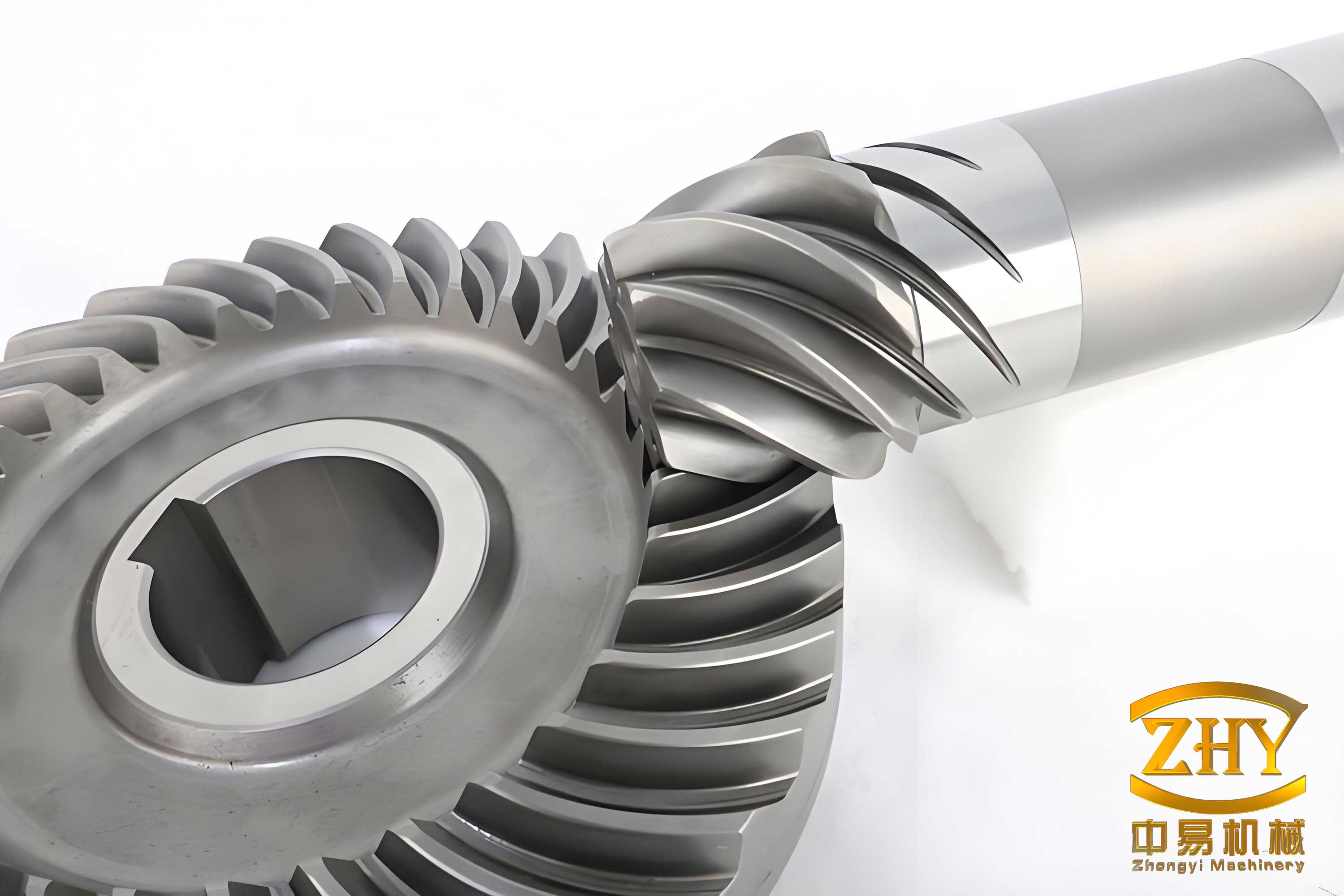
Geometric Modeling of the Spiral Bevel Gear Pair
The foundation of any accurate numerical analysis is a precise geometric model. For complex geometries like spiral bevel gears, which are generated via sophisticated machining processes, creating a faithful digital twin is a significant step. The modeling of a spiral bevel gear can be approached through several methodologies, each with its own merits and computational complexities. The primary methods are summarized in the table below.
| Method | Core Principle | Advantages | Challenges |
|---|---|---|---|
| Manufacturing Process Simulation | Geometric simulation of the cutting process using Boolean operations between a virtual cutter and gear blank. | Highly accurate representation of the actual manufactured tooth surface, including corrections. | Computationally intensive; requires precise definition of cutter geometry and machine kinematics. |
| Spatial Mesh Theory & Mathematical Modeling | Application of gear meshing theory and generation principles to calculate theoretical coordinates of points on the tooth surface, followed by reconstruction in CAD. | Provides a precise theoretical model; flexible for parametric studies and design variations. | Requires deep understanding of gear theory and robust programming for coordinate calculation. |
| Layer-Slicing Algorithm | Discretization of the workpiece into layers; the cutting shape at each instant is determined by intersecting the cutter profile with each layer of the blank. | Effective for visualizing the material removal process; can handle complex tool paths. | Accuracy depends on layer resolution; can be data-heavy for high-fidelity models. |
For the present study, the second method—based on spatial meshing theory and mathematical modeling—was employed to develop the three-dimensional model of the target spiral bevel gear pair. The fundamental parameters of the gear set, which is designed for a high-power reducer application, are provided in Table 2. These parameters served as the direct input for the mathematical model defining the tooth surfaces of both the pinion and the gear.
| Parameter | Pinion | Gear |
|---|---|---|
| Number of Teeth (z) | 21 | 51 |
| Module (m) / mm | 14.7 | |
| Shaft Angle / (°) | 90 | |
| Normal Pressure Angle (αn) / (°) | 20 | |
| Addendum Coefficient | 0.850 | 0.385 |
| Dedendum Coefficient | 0.188 | |
| Radial Modification Coefficient | +0.32 | -0.32 |
| Tangential Modification Coefficient | +0.11 | -0.11 |
| Mean Spiral Angle (βm) / (°) | 35 | |
| Hand of Spiral | Left | Right |
| Face Width / mm | 125 | |
Finite Element Model Development and Pre-stressed Modal Analysis Theory
Model Discretization and Boundary Conditions
The assembled three-dimensional model of the spiral bevel gear pair was imported into a commercial finite element analysis environment. The material was defined as a standard alloy steel with the following isotropic properties: Young’s Modulus, $E = 210\ GPa$; Poisson’s Ratio, $\mu = 0.3$; and Density, $\rho = 7800\ kg/m^3$. An unstructured tetrahedral mesh was generated for the assembly. To ensure accuracy in the contact stress region—a critical area for both static and dynamic response—local mesh refinement was applied to the active tooth flanks. The final mesh consisted of approximately 206,000 nodes and 125,000 elements.
The boundary conditions for the analysis were applied to simulate the operational mounting and loading:
- The inner cylindrical surface of the larger spiral bevel gear (the driven gear) was assigned a fixed support condition, simulating its connection to the output shaft housing.
- The inner bore of the smaller spiral bevel gear (the pinion) was constrained radially and axially but left free to rotate. A concentrated moment of $T = 6434\ N \cdot m$ was applied to this surface, representing the input torque.
- A surface-to-surface contact pair was defined between the meshing teeth. The contact type was specified as frictional, with a coefficient of friction appropriate for lubricated steel-on-steel contact.
Theoretical Background for Pre-stressed Modal Analysis
The dynamic behavior of a structure is governed by the fundamental equation of motion:
$$ [M]\{\ddot{x}\} + [C]\{\dot{x}\} + [K]\{x\} = \{F(t)\} $$
where $[M]$ is the mass matrix, $[C]$ is the damping matrix, $[K]$ is the stiffness matrix, $\{x\}$ is the displacement vector, and $\{F(t)\}$ is the time-varying force vector.
For a linear static analysis, all time-dependent and inertial terms are neglected, simplifying the equation to:
$$ [K]\{x\} = \{F\} $$
This analysis solves for the static deformation $\{x\}$ under the applied load $\{F\}$, from which stresses and strains are derived. The static stress state $\sigma_0$ influences the effective stiffness of the structure. This effect, known as stress stiffening, is captured by an additional matrix $[S]$ that is a function of the initial stress state: $[\sigma_0] \rightarrow [S]$.
A pre-stressed modal analysis accounts for this effect. It is a two-step process:
- Perform a linear static analysis to obtain the stress state under operational load: $[K]\{x\} = \{F\}$.
- Solve the eigenvalue problem using the updated stiffness matrix: $$ \left( [K] + [S] – \omega_i^2 [M] \right) \{\phi_i\} = 0 $$ where $\omega_i$ is the $i$-th natural circular frequency (rad/s) and $\{\phi_i\}$ is the corresponding mode shape vector. The natural frequency in Hz is $f_i = \omega_i / (2\pi)$.
This approach is crucial for components like spiral bevel gears, where the operational meshing loads significantly pre-stress the teeth, potentially altering their vibrational characteristics compared to the unloaded state.
Static Analysis Results for the Spiral Bevel Gear
The linear static analysis under the full input torque provides critical insight into the stress distribution and deformation of the spiral bevel gear pair. The results for the larger gear, which typically experiences the more critical bending stresses, are highlighted below. Key metrics such as equivalent (von-Mises) stress, contact pressure, and principal stress are examined to identify potential failure zones like tooth root bending and contact fatigue.
| Result Type | Maximum Value | Location | Engineering Significance |
|---|---|---|---|
| Equivalent Elastic Strain | Max at Pinion | Toe region (outer edge) of the pinion tooth. | Indicates area of maximum deformation, not necessarily max stress. |
| Von-Mises Stress | 687.3 MPa | Fillet region at the root of a contacting tooth. | Governed by distortion energy theory; critical for assessing yield failure under multi-axial stress. |
| Contact Pressure | 749.6 MPa | On the contact surface of the second engaged tooth pair. | Directly related to pitting and contact fatigue failure. Must be compared to allowable contact stress (e.g., 1428 MPa). |
| Maximum Principal Stress | 217.3 MPa | Root fillet at the toe of the second contacting tooth. | Tensile stress responsible for initiating bending fatigue cracks at the tooth root. |
The analysis confirms that the maximum contact pressure is well below the typical allowable contact fatigue stress for hardened gear steels, and the bending stresses are within acceptable limits for the given load. This establishes a baseline of structural integrity before evaluating dynamic response.
Modal Analysis: Natural Frequencies and Mode Shapes
The dynamic characteristics of the spiral bevel gear assembly were extracted through modal analysis. To quantify the effect of operational load, analyses were conducted in two states: the free (unloaded) state and the pre-stressed (loaded) state. The first six natural frequencies and descriptions of their corresponding mode shapes are compiled in Table 4. The primary mode shapes typically involve combinations of rocking, torsional, and bending deformations of the gear bodies, with the larger, less-constrained gear often exhibiting more complex patterns.
| Mode Order | Natural Frequency (Free State) $f_{free}$ [Hz] | Natural Frequency (Pre-stressed) $f_{pre}$ [Hz] | Percentage Change $\Delta f$ [%] | Characteristic Mode Shape Description |
|---|---|---|---|---|
| 1 | 1130.0 | 1132.1 | +0.19 | Coupled motion: Rocking of the large gear about its axis combined with radial/circumferential deformation of the pinion. |
| 2 | 1349.1 | 1352.9 | +0.28 | Lateral (in-plane) rocking or wobbling mode of the large gear. |
| 3 | 1382.3 | 1386.7 | +0.32 | Bending mode where one side (e.g., top) of the large gear rim deflects axially relative to the other. |
| 4 | 1441.0 | 1445.9 | +0.34 | First diametral bending mode: Opposing sides of the large gear rim deflect axially in opposite directions. |
| 5 | 1492.6 | 1494.2 | +0.11 | Higher-order diametral bending with four nodal diameters on the large gear. |
| 6 | 1711.0 | 1716.6 | +0.33 | Complex mode featuring multi-lobe deformation of the large gear coupled with pinion deformation. |
Discussion of Pre-stress Effects and Critical Speed
The results clearly demonstrate a consistent but small increase in all natural frequencies when pre-stress from the static load is considered. The frequency shift $\Delta f$ is positive and ranges from approximately 0.1% to 0.34%. This phenomenon is attributed to stress stiffening. The operational meshing loads induce compressive stresses in certain regions of the gear teeth and web, effectively increasing the component’s overall geometric stiffness $[K_{total}] = [K] + [S]$. Since the natural frequency $f_i$ is proportional to the square root of the stiffness-to-mass ratio, an increase in stiffness leads to a higher frequency, as approximated by:
$$ f_i \propto \sqrt{\frac{K_{total}}{M}} $$
The mass matrix $[M]$ remains unchanged. The mode shapes themselves were observed to be virtually identical between the two states, indicating that the load does not alter the fundamental deformation patterns of the spiral bevel gear system, only their associated frequencies.
A critical practical calculation involves the critical rotational speed $n_{cr}$, which is the shaft speed that coincides with a natural frequency of the system, potentially causing resonance. For the fundamental frequency (Mode 1 at ~1132 Hz), the critical speed is:
$$ n_{cr} = 60 \times f_1 = 60 \times 1132.1 \approx 67,926\ \text{RPM} $$
The nominal operating speed of such a high-power, high-torque reducer is typically orders of magnitude lower (often in the range of 1000-3000 RPM). Therefore, the analysis confirms that the system’s operating speed is far removed from its primary critical speeds, ensuring that internally generated excitations (e.g., from gear mesh frequency $f_{mesh} = n_{shaft} \times z / 60$) are unlikely to excite severe resonant vibrations in the spiral bevel gear pair itself. This is a vital conclusion for the dynamic design and operational safety of the reducer.
Conclusion and Engineering Implications
This comprehensive study successfully integrated advanced geometric modeling, linear static analysis, and pre-stressed modal analysis to evaluate the performance of a spiral bevel gear pair within a high-power reducer context. The parametric modeling approach based on meshing theory yielded an accurate digital prototype. The static analysis under full load identified the stress concentrations, confirming the gear’s design adequacy for static load capacity with respect to both bending and contact fatigue criteria.
The core of the dynamic investigation, the pre-stressed modal analysis, provided essential data: the first six natural frequencies and their associated mode shapes. The key finding is the quantifiable stress-stiffening effect, which causes a slight but systematic increase in all natural frequencies under load. Most importantly, the calculated critical speeds are extremely high compared to the intended operational range, indicating a low risk of resonance during normal service for this specific spiral bevel gear design.
These results form a crucial reference dataset for the dynamic design of the entire gear transmission system. They can be used to:
- Validate and refine analytical lumped-parameter models of the reducer.
- Guide the placement of sensors for condition monitoring by identifying sensitive vibrational nodes.
- Inform future design iterations aimed at shifting natural frequencies away from potential excitations (e.g., from engine orders or other components) by modifying mass or stiffness distribution.
- Serve as input for more complex, forced-response analyses or system-level multi-body dynamic simulations.
Further work could involve experimental modal analysis for validation, investigating the effects of housing stiffness, and performing transient dynamic analysis to assess response under fluctuating load conditions typical of scraper conveyor operations.