
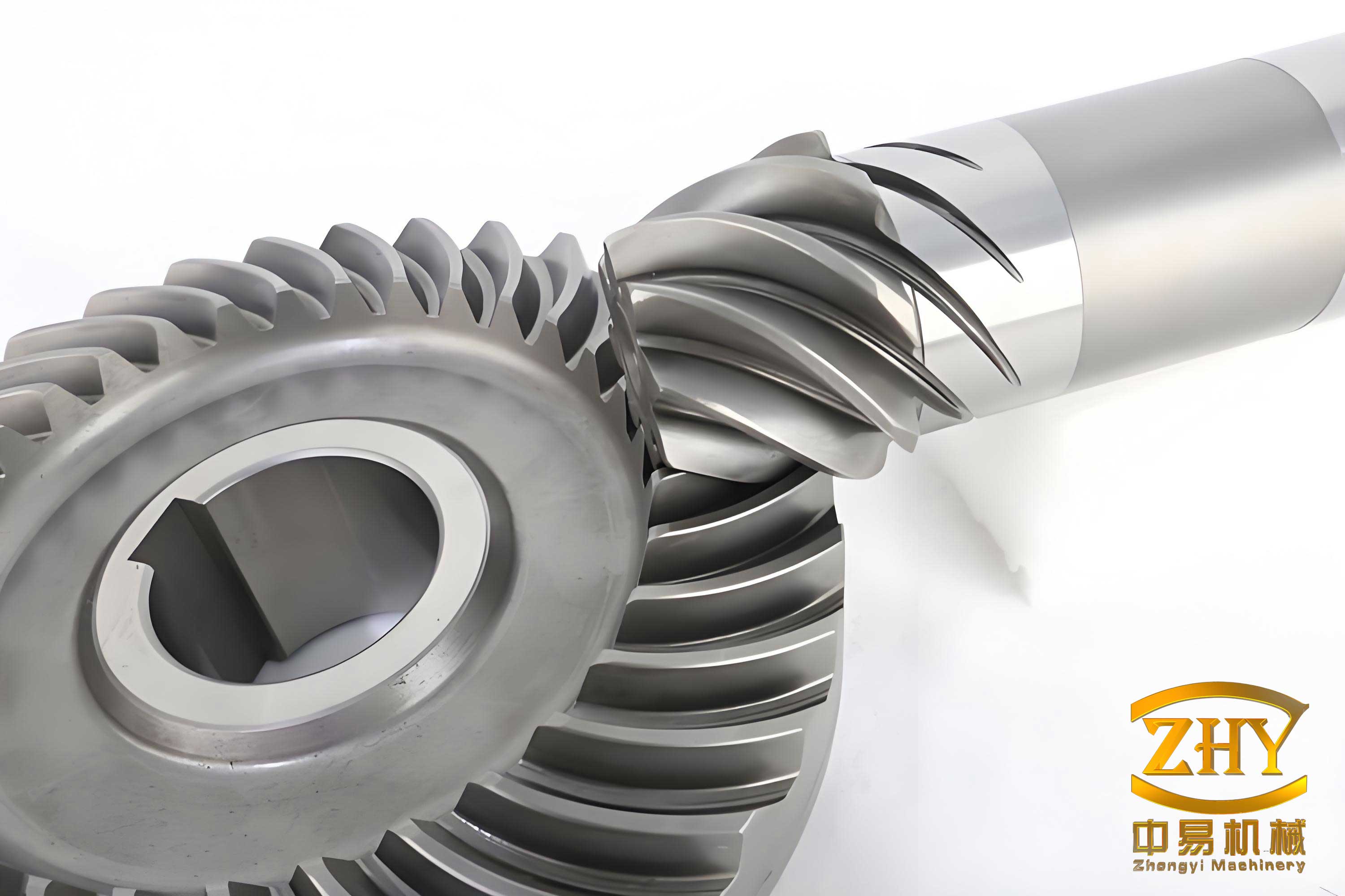
In the field of gear transmission with intersecting axes, although straight bevel gears are easier to machine than spiral bevel gears and do not generate axial forces during operation, spiral bevel gears surpass straight bevel gears in terms of transmission smoothness and load-bearing capacity. Therefore, spiral bevel gears are widely used in automotive, tractor, and mining machinery applications. The traditional manufacturing method for spiral bevel gears is cutting. However, cutting falls short of forging in terms of production efficiency, material consumption, and equipment investment. Due to the structural complexity of spiral bevel gear teeth, forging of spiral bevel gears is not commonly applied, primarily due to the complexity of molds and their machining. This article discusses a method for machining the tooth profile of a spiral bevel gear mold using mechanical cutting based on the requirements of the gear pair, aiming to improve mold production efficiency. It focuses on the calculation principles for tooth cutting, cutting experiments, and verification results.
The prototype gear pair referred to in this context is designed according to conventional engineering standards, featuring a standard tapered tooth system and processed using the Spread Blade Fixed Setting (SFT) method with cutter tilt. The convex and concave tooth surfaces of the gear are cut in one pass using a Gleason cutter, where the tooth surface is formed by the cutting edges of the cutter revolving around its axis, creating a conical surface. The pinion tooth surface is generated via a generating method. The forged ring gear mentioned here is designed with basic parameters following the standard ring gear, but manufactured via forging, while the pinion remains cut.
When machining the standard prototype ring gear via forming, to cut the root cone of the gear, the cutter axis should be perpendicular to the root cone generatrix of the prototype ring gear. The cutting cone surface represents the shape of the convex side of the prototype ring gear tooth. For machining the mold tooth concave surface, the cutting cone surface is formed by the outer cutting edges of the cutter revolving around its own axis. When using the forming method to process this mold, the cutter tip should cut the mold slot bottom, meaning the cutter axis is perpendicular to the mold root cone generatrix, which is perpendicular to the face cone generatrix of the prototype ring gear. Therefore, when the prototype ring gear has a tapered tooth system, the forged ring gear produced by the mold, if assumed to be cut by a tool, would have a cutter axis that does not coincide with that used for cutting the standard prototype ring gear. The angle between the two axes equals the sum of the root angle and face angle of the prototype ring gear.
To avoid this “secondary cutting” interference phenomenon, the mold is cut with a normal tilt of the cutter. After normal tilting, the cutter axis for machining the prototype ring gear and that for cutting the forging mold become even more misaligned, meaning there is an inherent form error between the tooth surfaces of the prototype ring gear and the forged ring gear. This error must be accounted for in the design of the spiral bevel gear mold.
Assuming the forged ring gear and the prototype standard ring gear tooth surfaces are overlaid, if a point on the surface has the same normal vector, it implies that the forged ring gear can also mesh normally with the standard pinion. Based on the root cone pressure angle, root cone spiral angle, and meshing conditions of the standard prototype ring gear, the root cone pressure angle and root cone spiral angle of the mold can be derived. By adjusting these angles, the normal vector at the reference point P on the mold tooth surface can match that of the prototype ring gear at point P.
The relationship between the root cone pressure angle and root cone spiral angle of the mold concave surface and those of the prototype ring gear tooth convex surface is given by:
$$ \phi_2 = \sin^{-1}(\cos\alpha \sin\phi_1 – \sin\alpha \sin\psi_1 \cos\phi_1) $$
$$ \psi_2 = \cos^{-1}\left(\frac{\cos\phi_1 \cos\psi_1}{\cos\phi_2}\right) $$
where \(\phi_1\) and \(\phi_2\) are the root cone pressure angles of the prototype ring gear convex surface and mold concave surface, respectively, and \(\psi_1\) and \(\psi_2\) are the root cone spiral angles of the prototype ring gear convex surface and mold concave surface, respectively. Similarly, for the mold convex surface and prototype ring gear concave surface:
$$ \phi’_2 = \sin^{-1}(\cos\alpha’ \sin\phi’_1 + \sin\alpha’ \sin\psi’_1 \cos\phi’_1) $$
$$ \psi’_2 = \cos^{-1}\left(\frac{\cos\phi’_1 \cos\psi’_1}{\cos\phi’_2}\right) $$
where \(\phi’_1\) and \(\phi’_2\) are the root cone pressure angles of the prototype ring gear concave surface and mold convex surface, respectively, and \(\psi’_1\) and \(\psi’_2\) are the root cone spiral angles of the prototype ring gear concave surface and mold convex surface, respectively. The reference point P is taken on the actual tooth surface of the prototype ring gear. The unit normal vector at point P can be expressed based on geometric relations. The root cone pressure angle at point P for the prototype ring gear is:
$$ \phi_1 = 90^\circ – \cos^{-1}\left(\frac{\vec{n} \cdot \vec{DP}}{|\vec{n}| |\vec{DP}|}\right) $$
The root cone spiral angle at point P is:
$$ \psi_1 = \cos^{-1}\left(\frac{\vec{PO’} \cdot \vec{DP}}{|\vec{PO’}| |\vec{DP}|}\right) $$
These formulas apply to both convex and concave surfaces, with the normal vector direction differing (outward for convex, inward for concave). With \(\phi_1\) and \(\psi_1\), equations above yield the spiral and pressure angles for the mold surfaces at point P.
For mold cutting calculations, excessive normal tilt angle can distort the tooth surface, so a minimal tilt is used while avoiding secondary cutting. If the normal tilt angle is \(i_n\), the cutter pressure angle can be determined based on the mold pressure angle. After tilting, the outer blade pressure angle increases, and the inner blade pressure angle decreases. Thus, for cutter selection, the blade pressure angles are:
$$ \varphi_{\text{outer}} = \phi_2 – i_n $$
$$ \varphi_{\text{inner}} = \phi’_2 + i_n $$
The cutter tip radii can be calculated from the reference point position and cutter pressure angle. Machine adjustment parameters include the height of the reference point \(b_g\), the forming point radius \(r\), the root cone generatrix length \(L\) at point P, and machine constant \(U_0\) (e.g., for Gleason No. 16, \(U_0 = 368.3 \text{ mm}\)). The coordinates of the cutter tilt center \(Q’\) are:
$$ H = L – r \sin\psi_2 $$
$$ V = r \cos\psi_2 $$
where \(r = r_c – (U_0 – b_g)\sin i_n\), with \(r_c\) as the cutter radius. After tilting, the workpiece must be moved along the machine axis by a distance \(\Delta h\):
$$ \Delta h = (U_0 – b_g)(1 – \cos i_n) – r_c \sin i_n $$
If \(\Delta h\) is positive, the worktable retreats from the cutter; if negative, it advances. The cutter position parameters are:
$$ s = \sqrt{H^2 + V^2} $$
$$ q = \tan^{-1}\left(\frac{V}{H}\right) $$
Other parameters include total tilt angle \(i = i_n\) (for left-hand spiral bevel gear mold), tilt direction angle \(\theta = q – \psi_2\), cutter rotation angle \(J = q – \psi_2\), and mold blank mounting root cone angle equal to the prototype ring gear face cone angle. Since the prototype ring gear tooth slot is cut in one pass, the mold tooth surface requires two passes: parameters for concave and convex surfaces are calculated separately based on the prototype ring gear’s convex and concave surface data.
We conducted cutting experiments on a WMW gear milling machine (simulating Gleason No. 16). Due to constraints, custom tools were not feasible; instead, gear pressure angles were back-calculated from available tools. The basic parameters of the prototype spiral bevel gear pair are summarized in Table 1.
| Parameter | Pinion | Ring Gear |
|---|---|---|
| Number of teeth, z | 9 | 37 |
| Module, m | 6.5 mm | 6.5 mm |
| Midpoint root cone spiral angle, ψ | 35° | 35° |
| Root cone pressure angle, φ (convex) | – | 25.995° |
| Root cone pressure angle, φ’ (concave) | – | 18.866° |
| Pitch cone angle, γ or Γ | 14.058° | 86.942° |
| Outer pitch distance, A₀ | 120.4214 mm | 120.4214 mm |
| Face width, F | 28 mm | 28 mm |
| Shaft angle, Σ | 101° | 101° |
| Hand of spiral | – | Right-hand |
Mold parameters such as tooth height were derived from the ring gear parameters. The pressure angles and spiral angles at the reference point on the mold tooth surface are shown in Table 2.
| Surface Type | Root Cone Pressure Angle, φ (°) | Root Cone Spiral Angle, ψ (°) |
|---|---|---|
| Mold Concave Surface | 22.50 | 35.320 |
| Mold Convex Surface | 22.50 | 34.775 |
After calculation and selection, the cutter and machine adjustment parameters for mold cutting are listed in Table 3.
| Parameter | For Mold Concave Surface | For Mold Convex Surface |
|---|---|---|
| Cutter pressure angle, φ_c (°) | 14 (outer blade) | 14 (inner blade) |
| Cutter tip radius, r_c (mm) | 153.8403 (outer) | 165.8651 (outer) |
| Normal tilt angle, i_n (°) | 8.5 | 8.5 |
| Worktable retreat, Δh (mm) | 18.945 | 20.277 |
| Cutter position, s (mm) | 96.372 | 97.992 |
| Swivel angle, q (°) | 57.840 | 65.776 |
| Total tilt angle, i (°) | 8.5 | 8.5 |
| Cutter rotation angle, J (°) | 21.925 | 31.006 |
| Mounting root cone angle, Γ (°) | 91.321 | 91.321 |
We performed cutting of the mold concave surface based on these parameters and simulated forging using industrial nylon casting. To complete rolling tests, a matching pinion was also required. After cutting the mold tooth surface via the tilted forming method, second-order geometric parameters of the forged ring gear tooth surface, such as principal directions and curvatures, were obtained. The pinion calculation followed “pre-control” theory, determining second-order parameters under a “mismatch” condition with the forged ring gear, enabling pinion cutting parameter computation. The pinion cutting process is not detailed here.
Using the simulated forged ring gear and pinion machined via pre-control theory, we conducted rolling tests. The mold, simulated forged ring gear (made of industrial nylon), and pinion were assembled. The rolling test showed satisfactory contact patterns, indicating correct theoretical derivation and calculation. The contact pattern on the ring gear convex surface was transferred via ink, demonstrating good meshing. Minor shrinkage during nylon solidification was mitigated by anti-deformation measures during casting, and cutter position adjustments during pinion cutting further refined the contact. This validates the approach for spiral bevel gear mold machining.
The manufacturing of spiral bevel gears through forging molds offers significant advantages in efficiency and material usage. However, the complexity of spiral bevel gear tooth geometry demands precise mold design and machining. Our method leverages mechanical cutting to produce molds with accurate tooth profiles, enabling the production of high-quality forged spiral bevel gears. The calculations involve intricate relationships between pressure angles, spiral angles, and cutter parameters, all tailored to ensure proper meshing between the forged ring gear and a cut pinion. The experimental results confirm that the derived formulas and adjustment settings yield functional molds, paving the way for broader application of forging in spiral bevel gear production. Future work could explore optimization of tilt angles and cutter designs to further reduce errors and enhance performance for various spiral bevel gear configurations.
In summary, the successful implementation of this cutting calculation and experiment underscores the feasibility of using machined molds for forging spiral bevel gears. This approach bridges the gap between traditional cutting and advanced forging, potentially revolutionizing manufacturing processes in industries reliant on durable and efficient spiral bevel gear transmissions. The integration of theoretical modeling with practical machining steps ensures that the spiral bevel gears produced meet rigorous standards for meshing and load capacity, thereby expanding the horizons for gear technology.