
In modern engineering applications, particularly in aviation, marine, and automotive industries, spiral bevel gears play a critical role due to their ability to transmit power between non-parallel shafts with high efficiency and reliability. The dynamic behavior of spiral bevel gear systems, especially when mounted on elastic supports such as those incorporating squeeze film dampers, exhibits complex nonlinear characteristics. These nonlinearities arise from factors like time-varying mesh stiffness, backlash, and the coupling effects between gears and supports. Understanding the vibration properties of spiral bevel gear systems is essential for enhancing performance, reducing noise, and preventing failures in high-speed machinery like helicopter transmissions and jet engines. This study focuses on analyzing the domain boundary structures in parameter planes for a spiral bevel gear system with elastic supports, aiming to provide insights for vibration control and parameter design.
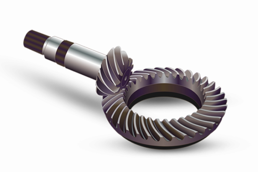
The vibration analysis of spiral bevel gear systems with elastic supports constitutes a high-dimensional nonlinear dynamics problem. Traditional studies often examine dynamics under fixed parameter values, but in practical scenarios, parameters like support stiffness and damping vary interdependently due to coupling effects. Therefore, investigating domain boundaries in parameter planes—where parameters such as mesh frequency, support stiffness, and support damping are varied simultaneously—offers a more realistic perspective. This approach helps identify regions of periodic and chaotic motion, bifurcation patterns, and stability domains, which are crucial for predictive maintenance and active control strategies. In this work, I develop a nonlinear dynamic model for a spiral bevel gear system, solve it using the Adomian decomposition method, and employ cell mapping combined with Poincaré section concepts to explore domain boundaries in key parameter planes. The findings contribute to the design and optimization of spiral bevel gear systems in aerospace applications.
The spiral bevel gear system considered here is based on a central shaft transmission in a novel aero-engine. The system includes a pair of spiral bevel gears mounted on elastic supports, which introduce additional compliance and damping. To capture the essential dynamics, a 7-degree-of-freedom (DOF) nonlinear model is established using lumped parameter methods. This model accounts for translational and rotational motions of both gears, as well as interactions through mesh forces and support reactions. The global coordinate system is defined with an axis angle of 90°, and vibrations are assumed to exclude swing motions, focusing on three translational and one rotational DOF per gear. The degrees of freedom are denoted as: \( X_p, Y_p, Z_p, \theta_p \) for the pinion (active gear) and \( X_g, Y_g, Z_g, \theta_g \) for the gear (driven gear), where \( X, Y, Z \) represent translational displacements along coordinate axes, and \( \theta \) represents angular displacement about the axis.
The support stiffness and damping parameters are defined as follows: \( k_{xp}, c_{xp} \) for pinion X-direction; \( k_{yp}, c_{yp} \) for pinion Y-direction; \( k_{zp}, c_{zp} \) for pinion Z-direction; \( k_{xg}, c_{xg} \) for gear X-direction; \( k_{yg}, c_{yg} \) for gear Y-direction; and \( k_{zg}, c_{zg} \) for gear Z-direction. The mesh stiffness \( k_h(t) \) and damping \( c_h \) model the gear pair interaction, while \( T_p \) and \( T_g \) are input and output torques, \( m_p \) and \( m_g \) are masses, and \( J_p \) and \( J_g \) are moments of inertia. The relative displacement along the mesh line, considering vibrations and manufacturing errors, is given by:
$$ \lambda_n = (X_p – X_g)c_1 – (Y_p – Y_g)c_2 – (Z_p – Z_g + r_p \theta_p – r_g \theta_g)c_3 – e_n(t) $$
Here, \( c_1 = \cos \delta_p \sin \alpha_n \), \( c_2 = \cos \delta_p \cos \alpha_n \sin \beta_m \), \( c_3 = \cos \alpha_n \cos \beta_m \), with \( \delta_p \) as the pinion pitch cone angle, \( \alpha_n \) as the normal pressure angle, \( \beta_m \) as the mean spiral angle, and \( r_p, r_g \) as pitch radii. The static transmission error \( e_n(t) \) is expressed as a Fourier series:
$$ e_n(t) = \sum_{l=1}^{N_e} A_{el} \cos(l \Psi_h t + \Upsilon_{el}) $$
where \( A_{el} \) is amplitude, \( \Psi_h \) is mesh frequency, and \( \Upsilon_{el} \) is phase angle. The nonlinear dynamic equations for the spiral bevel gear system are derived from Newton’s second law:
$$ \begin{aligned}
m_p \ddot{X}_p + c_{xp} \dot{X}_p + k_{xp} X_p &= F_x \\
m_p \ddot{Y}_p + c_{yp} \dot{Y}_p + k_{yp} Y_p &= F_y \\
m_p \ddot{Z}_p + c_{zp} \dot{Z}_p + k_{zp} Z_p &= F_z \\
J_p \ddot{\theta}_p + F_z r_p &= T_p \\
m_g \ddot{X}_g + c_{xg} \dot{X}_g + k_{xg} X_g &= -F_x \\
m_g \ddot{Y}_g + c_{yg} \dot{Y}_g + k_{yg} Y_g &= -F_y \\
m_g \ddot{Z}_g + c_{zg} \dot{Z}_g + k_{zg} Z_g &= -F_z \\
J_g \ddot{\theta}_g – F_z r_g &= -T_g
\end{aligned} $$
The mesh force components \( F_x, F_y, F_z \) are derived from the normal dynamic load \( F_n \), which includes nonlinearities due to backlash. The normal load is:
$$ F_n = k_h(t) f(\lambda_n) + c_h \dot{\lambda}_n $$
with the backlash function defined as:
$$ f(\lambda_n) = \begin{cases}
\lambda_n – b_m & \lambda_n > b_m \\
0 & |\lambda_n| \le b_m \\
\lambda_n + b_m & \lambda_n < -b_m
\end{cases} $$
where \( b_m \) is half the backlash. The force components are: \( F_x = -c_4 F_n \), \( F_y = c_5 F_n \), \( F_z = c_6 F_n \), with \( c_4 = \sin \alpha_n \cos \delta_p + \cos \alpha_n \sin \beta_m \sin \delta_p \), \( c_5 = \sin \alpha_n \sin \delta_p – \cos \alpha_n \sin \beta_m \cos \delta_p \), and \( c_6 = \cos \alpha_n \sin \beta_m \). By introducing the dimensionless relative displacement \( \lambda = \lambda_n / b_m \) and combining the torsional equations, the system is reduced to a set of dimensionless equations. The equivalent mass is \( m_e = J_p J_g / (r_p^2 J_g + r_g^2 J_p) \), and the dimensionless equations become:
$$ \begin{aligned}
\ddot{x}_p + 2\zeta_{xp} \dot{x}_p + 2\zeta_{hp} c_4 \dot{\lambda} + \kappa_{xp} x_p + \kappa_{hp} c_4 c f(\lambda) &= 0 \\
\ddot{y}_p + 2\zeta_{yp} \dot{y}_p – 2\zeta_{hp} c_5 \dot{\lambda} + \kappa_{yp} y_p – \kappa_{hp} c_5 f(\lambda) &= 0 \\
\ddot{z}_p + 2\zeta_{zp} \dot{z}_p – 2\zeta_{hp} c_6 \dot{\lambda} + \kappa_{zp} z_p – \kappa_{hp} c_6 f(\lambda) &= 0 \\
\ddot{x}_g + 2\zeta_{xg} \dot{x}_g – 2\zeta_{hg} c_4 \dot{\lambda} + \kappa_{xg} x_g – \kappa_{hg} c_4 f(\lambda) &= 0 \\
\ddot{y}_g + 2\zeta_{yg} \dot{y}_g + 2\zeta_{hg} c_5 \dot{\lambda} + \kappa_{yg} y_g + \kappa_{hg} c_5 f(\lambda) &= 0 \\
\ddot{z}_g + 2\zeta_{zg} \dot{z}_g + 2\zeta_{hg} c_6 \dot{\lambda} + \kappa_{zg} z_g + \kappa_{hg} c_6 f(\lambda) &= 0 \\
-c_1 \ddot{x}_p + c_2 \ddot{y}_p + c_3 \ddot{z}_p + c_1 \ddot{x}_g – c_2 \ddot{y}_g – c_3 \ddot{z}_g + \ddot{\lambda} + 2\zeta_h c_3 c_6 \dot{\lambda} + \kappa_h c_3 c_6 f(\lambda) &= f_{pm} + f_{pv} + f_e
\end{aligned} $$
Dimensionless parameters are defined as: \( x_j = X_j / b_m \), \( y_j = Y_j / b_m \), \( z_j = Z_j / b_m \), \( \tau = \omega_n t \) with \( \omega_n = \sqrt{k_m / m_e} \), \( \omega_{ij} = \sqrt{k_{ij} / m_j} \), \( \zeta_{ij} = c_{ij} / (2 m_j \omega_n) \), \( \kappa_{ij} = \omega_{ij}^2 / \omega_n^2 \), \( \zeta_{hj} = c_h / (2 m_j \omega_n) \), \( \kappa_{hj} = k_h(\tau) / (m_j \omega_n^2) \), \( \zeta_h = c_h / (2 m_e \omega_n) \), \( \omega_h = \Psi_h / \omega_n \), \( \omega_F = \Psi_F / \omega_n \), and \( \kappa_h = 1 + \sum_{i=1}^{N_k} (A_{kl} / k_m) \cos(l \omega_h \tau + \Upsilon_{kl}) \). The excitation terms are \( f_{pm} = F_{pm} / (m_e b_m \omega_n^2) \), \( f_{pv} = F_{pv} / (m_e b_m \omega_n^2) \), and \( f_e = \sum_{l=1}^{N_e} (A_{el} / b_m) (l \omega_h)^2 \cos(l \omega_h \tau + \Upsilon_{el}) \). For the spiral bevel gear system studied, parameters are based on an aero-engine application: pinion teeth \( Z_p = 38 \), gear teeth \( Z_g = 51 \), \( \delta_p = 36.68972^\circ \), \( \alpha_n = 20^\circ \), \( \beta_m = 20^\circ \). Dimensionless values are set as: \( \zeta_{hp} = \zeta_{hg} = 0.0125 \), \( \zeta_h = 0.05 \), \( k_{hp} = k_{hg} = 0.5 \), \( f_{pm} = 0.1 \), \( f_{pv} = 0 \), \( k_h = 1 + 0.2 \cos(\omega_h \tau) \), \( f_e = 0.2 \omega_h^2 \cos(\omega_h \tau) \), \( \zeta_{ip} = \zeta_{ig} = 0.01 \) for \( i = x, y, z \), and \( k_{ip} = k_{ig} = 1 \).
To solve these nonlinear equations, the Adomian decomposition method is employed. This technique is effective for handling nonlinearities by decomposing the solution into a series of polynomials. The state vector is defined as \( \mathbf{Y}(\tau) = \{ y_1, y_2, \dots, y_{14} \}^T = \{ x_p, \dot{x}_p, y_p, \dot{y}_p, z_p, \dot{z}_p, x_g, \dot{x}_g, y_g, \dot{y}_g, z_g, \dot{z}_g, \lambda, \dot{\lambda} \}^T \), transforming the system into state-space form: \( \dot{\mathbf{Y}}(\tau) = \mathbf{H} \mathbf{Y}(\tau) + \mathbf{N}(\tau) + \mathbf{G}(\tau) \), where \( \mathbf{H} \) is the linear coefficient matrix, \( \mathbf{N} \) is the nonlinear vector, and \( \mathbf{G} \) is the excitation vector. The Adomian solution is expressed as a series: \( \mathbf{y}(\tau) = \sum_{n=0}^{\infty} \mathbf{y}_n \), with terms computed iteratively. For this spiral bevel gear system, the Adomian polynomials are derived based on the backlash function, and convergence is achieved by truncating after six terms. The initial conditions are taken as zero for simplicity, reflecting a startup scenario.
The primary focus of this analysis is to investigate domain boundaries in parameter planes for the spiral bevel gear system. Domain boundaries represent bifurcation sets where attractors (e.g., periodic or chaotic motions) change abruptly with parameter variations. Using cell mapping combined with Poincaré sections, the parameter planes are discretized into cells, and the periodicity of motion at each cell center is computed. Cells with the same period number form periodic domains, while chaotic motions form chaotic domains. The boundaries between these domains reveal bifurcation structures, such as period-doubling or Hopf bifurcations, which are critical for understanding system stability and designing control strategies. Three key parameter planes are examined: mesh frequency versus support stiffness (\( \omega_h – k \)), mesh frequency versus support damping (\( \omega_h – \zeta \)), and support stiffness versus support damping (\( k – \zeta \)). These planes capture the interplay between operational and support parameters in spiral bevel gear systems.
In the \( \omega_h – k \) parameter plane, with \( \omega_h \) ranging from 0.02 to 1.0 and support stiffness \( k \) from 0.02 to 1.0, the domain boundaries exhibit a clear period-doubling bifurcation pattern. The cell mapping results, using a 50×50 grid, show distinct regions for period-1 (P1), period-2 (P2), period-4 (P4), period-8 (P8), period-16 (P16), and chaotic motions. Table 1 summarizes the parameter ranges for these domains based on the analysis.
| Domain | Mesh Frequency (\( \omega_h \)) Range | Support Stiffness (\( k \)) Range | Characteristics |
|---|---|---|---|
| P1 | 0.02 – 0.6 | 0.02 – 0.4 | Stable periodic motion |
| P2 | 0.1 – 0.8 | 0.05 – 0.6 | First period-doubling |
| P4 | 0.2 – 0.9 | 0.1 – 0.7 | Second period-doubling |
| P8 | 0.3 – 1.0 | 0.15 – 0.8 | Third period-doubling |
| P16 | 0.4 – 1.0 | 0.2 – 0.9 | Fourth period-doubling |
| Chaos | 0.5 – 1.0 | 0.25 – 1.0 | Chaotic vibrations |
The bifurcation progression follows the Feigenbaum scenario, where increasing \( \omega_h \) or decreasing \( k \) leads to chaos through period-doubling. Notably, in the region \( \omega_h = 0.6 – 0.86 \), sharp transitions (cusp catastrophes) occur, making this area sensitive to parameter changes. This irregular zone complicates control efforts, as small perturbations can shift the system between periodic domains. Additionally, within the P1 domain, isolated P2 windows exist, and the chaotic region contains narrow periodic windows, indicating crises in the chaotic attractor. These features underscore the complexity of spiral bevel gear dynamics and highlight the need for careful parameter selection in design.
For the \( \omega_h – \zeta \) parameter plane, with \( \omega_h \) from 0.02 to 1.0 and support damping \( \zeta \) from 0.002 to 0.1, the domain boundaries reveal a quasi-periodic bifurcation structure. The results, shown in Table 2, indicate that as mesh frequency increases, higher damping is required to maintain periodic motion, reflecting the energy dissipation needs in spiral bevel gear systems.
| Domain | Mesh Frequency (\( \omega_h \)) Range | Support Damping (\( \zeta \)) Range | Characteristics |
|---|---|---|---|
| P1 | 0.02 – 0.4 | 0.055 – 0.1 | Stable periodic motion |
| P2 | 0.05 – 0.6 | 0.03 – 0.08 | Period-doubling onset |
| P3 | 0.1 – 0.7 | 0.02 – 0.06 | Quasi-periodic step |
| P4 | 0.15 – 0.8 | 0.015 – 0.05 | Further bifurcation |
| P5 | 0.2 – 0.9 | 0.01 – 0.04 | Complex periodic motion |
| Chaos | 0.25 – 1.0 | 0.002 – 0.03 | Chaotic regime |
The domain boundaries are more diffuse compared to the stiffness plane, suggesting a smoother transition to chaos. The spiral bevel gear system exhibits robust periodic motion for \( \zeta > 0.055 \), which is a key design insight. Like in the previous plane, periodic windows are embedded in chaotic regions, emphasizing the intricate dynamics of spiral bevel gears under varying damping conditions.
In the \( k – \zeta \) parameter plane, with \( k \) from 0.03 to 1.5 and \( \zeta \) from 0.002 to 0.1, the domain boundaries primarily follow Hopf bifurcation patterns. This plane is particularly relevant for real-world spiral bevel gear systems, as support stiffness and damping often vary together due to material and design constraints. Table 3 summarizes the findings, highlighting distinct zones for periodic and chaotic behaviors.
| Domain | Support Stiffness (\( k \)) Range | Support Damping (\( \zeta \)) Range | Characteristics |
|---|---|---|---|
| P1 | 0.9 – 1.5 | 0.03 – 0.1 | Stable periodic motion |
| P2 | 0.7 – 1.2 | 0.02 – 0.07 | Hopf bifurcation onset |
| P3 | 0.5 – 1.0 | 0.015 – 0.05 | Secondary bifurcation |
| P4 | 0.4 – 0.9 | 0.01 – 0.04 | Periodic windows |
| P5 | 0.3 – 0.8 | 0.005 – 0.03 | Complex motions |
| Chaos | 0.03 – 0.6 | 0.002 – 0.02 | Chaotic vibrations |
A notable irregular zone exists for \( k = 0.9 – 1.08 \), where abrupt transitions from periodic to chaotic motion occur, similar to crises in nonlinear systems. This region should be avoided in design due to its sensitivity. For \( \zeta = 0.03 – 0.90 \) and \( k = 1.08 – 1.5 \), the system undergoes Hopf bifurcations leading to chaos, representing a regular progression. The presence of period-1, period-2, period-3, and period-5 windows within the chaotic domain points to possible control points for stabilizing spiral bevel gear vibrations.
The analysis of domain boundaries provides valuable insights for the design and control of spiral bevel gear systems. In terms of vibration suppression, parameters should be selected within stable periodic domains, such as the P1 region in the \( k – \zeta \) plane where \( k \) is relatively low and \( \zeta \) is high. This aligns with practical engineering where softer supports with adequate damping can mitigate nonlinear effects. For active control strategies, the domain boundaries offer leverage points: small parameter adjustments near boundaries can induce desired transitions, e.g., from chaos to periodicity. The bifurcation structures also aid in predicting vibration forms based on operational ranges; for instance, at high mesh frequencies, reducing support stiffness may trigger period-doubling routes to chaos in spiral bevel gears.
To further quantify the dynamics, key nonlinear phenomena are summarized using mathematical descriptors. The Lyapunov exponents, though not computed here, would typically show positive values in chaotic domains for spiral bevel gear systems. The bifurcation diagrams can be derived from the Poincaré maps, illustrating how attractors evolve with parameters. For example, the period-doubling cascade in the \( \omega_h – k \) plane follows the logistic map analogy, with the Feigenbaum constant \( \delta \approx 4.669 \) applicable. The dimensionless equations also highlight the role of nonlinear terms: the backlash function \( f(\lambda) \) introduces piecewise linearity, while time-varying mesh stiffness \( \kappa_h(\tau) \) adds parametric excitation. These factors combine to produce rich dynamics in spiral bevel gear transmissions.
In practical applications, such as aero-engines, the spiral bevel gear system operates under varying speeds and loads. The parameter plane analysis suggests that maintaining support stiffness below 0.4 and damping above 0.055 can ensure periodic motion across a wide mesh frequency range. However, during startup or shutdown, parameters may traverse chaotic regions, necessitating transient control. The domain boundary maps serve as charts for avoiding undesirable vibrations; for instance, designers can use the \( k – \zeta \) plot to select support properties that keep the system in the P1 domain. Additionally, the presence of periodic windows in chaos implies that targeted perturbations (e.g., via active actuators) could stabilize the spiral bevel gear system even in nominally chaotic regimes.
The Adomian decomposition method proved effective for solving the high-dimensional nonlinear equations of the spiral bevel gear system. Its iterative nature allows handling complex nonlinearities without linearization, preserving accuracy. The solution converges within six terms for the given parameters, demonstrating efficiency. Compared to numerical integration, this method provides analytical insights, though it requires careful treatment of discontinuities from backlash. For future work, extending the model to include more DOFs (e.g., housing vibrations) or additional nonlinearities (e.g., tooth friction) could enhance realism. Moreover, experimental validation on spiral bevel gear test rigs would corroborate the predicted domain boundaries.
In conclusion, the study of domain boundaries in parameter planes for spiral bevel gear systems with elastic supports reveals intricate nonlinear dynamics. The \( \omega_h – k \) plane shows period-doubling bifurcations, the \( \omega_h – \zeta \) plane exhibits quasi-periodic routes, and the \( k – \zeta \) plane displays Hopf bifurcations, each with distinct stable and chaotic regions. These findings emphasize the importance of holistic parameter design in spiral bevel gear applications. Key recommendations include: avoiding parameter sets in irregular zones (e.g., \( \omega_h = 0.6-0.86 \) with variable \( k \)), opting for lower stiffness and higher damping to maintain periodicity, and leveraging boundary sensitivities for active control. The spiral bevel gear, as a critical transmission component, benefits from such nonlinear analyses to ensure reliability and performance in demanding environments like aviation. This research lays groundwork for advanced vibration management strategies in spiral bevel gear systems, contributing to safer and more efficient machinery.
The nonlinear dynamics of spiral bevel gear systems are governed by dimensionless equations that encapsulate mesh and support interactions. For reference, the key equations are restated here. The state-space formulation is: $$ \dot{\mathbf{Y}} = \mathbf{H} \mathbf{Y} + \mathbf{N} + \mathbf{G} $$ with \( \mathbf{Y} \) as defined earlier. The nonlinear vector \( \mathbf{N} \) depends on \( f(\lambda) \), and the linear matrix \( \mathbf{H} \) includes damping and stiffness terms. The Adomian solution series is: $$ \mathbf{y}(\tau) = \sum_{n=0}^{\infty} \mathbf{y}_n, \quad \mathbf{y}_0 = e^{\mathbf{H}\tau} \mathbf{y}_0 + \int_0^\tau e^{\mathbf{H}(\tau-\eta)} \mathbf{G}(\eta) d\eta, \quad \mathbf{y}_{j+1} = \int_0^\tau e^{\mathbf{H}(\tau-\eta)} \mathbf{a}_j d\eta $$ where \( \mathbf{a}_j \) are Adomian polynomials. For the spiral bevel gear system, these polynomials simplify based on the backlash function thresholds, enabling efficient computation.
To summarize the parameter effects, the following correlations are observed for spiral bevel gear vibrations: increasing mesh frequency generally destabilizes the system, requiring higher damping or lower stiffness for control; support stiffness reduction promotes period-doubling bifurcations; and support damping increase stabilizes periodic motion. These trends are captured in the domain boundary plots, which serve as design tools. Ultimately, the spiral bevel gear system’s dynamics are a microcosm of broader nonlinear phenomena, with implications for rotating machinery health monitoring and control. Continued research on spiral bevel gears will further unravel their complex behaviors, driving innovations in mechanical transmissions.