
In my extensive experience with power transmission systems, the design of spiral gear pairs, a type of crossed helical gear drive, presents unique challenges and opportunities. Unlike parallel-axis helical gears, spiral gears operate on non-parallel, non-intersecting axes. While an individual spiral gear is manufactured identically to a standard helical gear, their meshing behavior is fundamentally different due to this axis misalignment. This configuration results in point contact between the tooth surfaces, as opposed to the line contact found in parallel-axis designs. This singular contact characteristic, combined with inherently high sliding velocities, dictates that the primary failure modes are wear and scuffing (pitting), making precise contact stress analysis the cornerstone of reliable design. This article details my comprehensive methodology for the exact calculation of tooth surface contact strength in spiral gear drives, moving beyond empirical formulas to a rigorous analytical foundation.
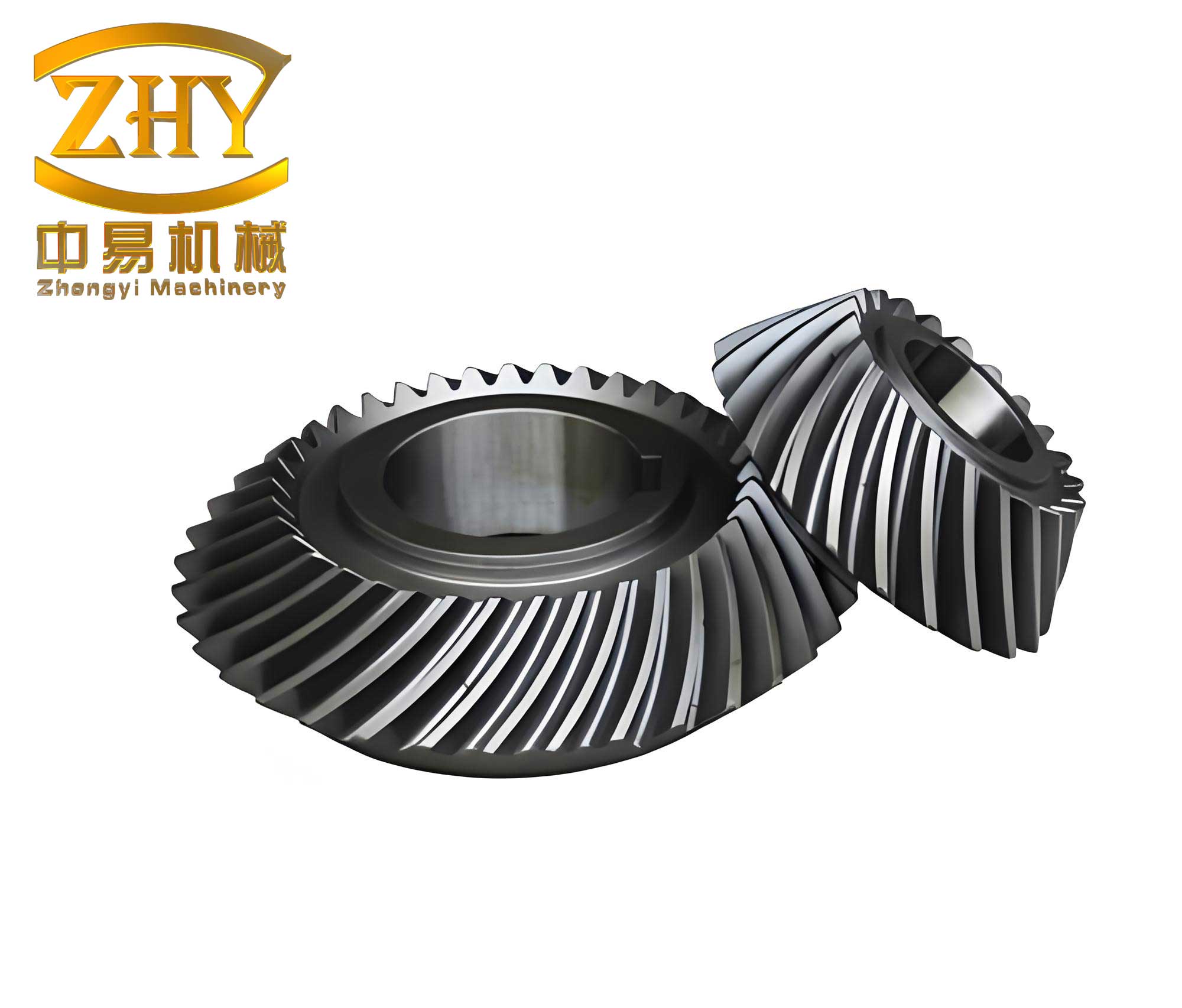
The fundamental kinematics of a spiral gear pair can be effectively visualized by considering both gears in mesh with a common imaginary rack, as shown conceptually in the figure. The point of tangency between the two pitch cylinders is the pitch point, P. The shaft angle, $\Sigma$, is the critical geometric parameter defined by the helix angles $\beta_1$ and $\beta_2$ of the two gears. The relationship is $\Sigma = |\beta_1 + \beta_2|$, where the signs of the helix angles are positive for right-hand helices and negative for left-hand ones. For the pair to mesh, the normal modules must be equal. The instantaneous velocity ratio is not constant but depends on the ratio of the base circle radii. However, for standard gears with pitch cylinders coinciding with reference cylinders, the velocity ratio can be expressed in terms of tooth numbers $z$ and helix angles:
$$
i = \frac{\omega_1}{\omega_2} = \frac{z_2}{z_1} = \frac{d_2 \cos \beta_2}{d_1 \cos \beta_1}
$$
where $d_1$ and $d_2$ are the reference diameters. A critical aspect of spiral gear operation is the high sliding velocity $v_s$ along the tooth, which can be decomposed from the relative motion at the pitch point. This high sliding action is responsible for the tendency towards wear and necessitates careful material and lubrication selection.
The core of my analytical approach lies in applying Hertzian theory for elastic contact to the specific geometry of meshing spiral gear teeth. At the contact point, the tooth surfaces can be approximated as two cylinders in point contact, with their axes non-parallel. Due to elastic deformation, the contact spreads over a small elliptical area. The maximum contact (Hertzian) stress, $\sigma_H$, is given by the universal formula:
$$
\sigma_H = \sqrt{ \frac{F_{cn} \cdot n_E}{\pi \cdot \rho_{\Sigma} \cdot \zeta} }
$$
Where:
$F_{cn}$ = Normal load applied along the common normal (line of action).
$n_E$ = Material coefficient, $n_E = \frac{4}{1/\mu_1^2 + 1/\mu_2^2}$, with $\mu$ being Poisson’s ratio.
$\rho_{\Sigma}$ = Equivalent curvature radius at the contact point.
$\zeta$ = Geometry coefficient for the elliptical contact area, dependent on the Hertzian auxiliary angle $\theta$.
The primary task is to express all these parameters in terms of the fundamental spiral gear design variables. Let’s derive them step by step. The normal load $F_{cn}$ is related to the transmitted torque. For a pinion (gear 1) transmitting torque $T_1$, the tangential force $F_t$ at the reference diameter $d_1$ is $F_t = 2T_1 / d_1$. Considering the helical geometry, the normal force is:
$$
F_{cn} = \frac{F_t}{\cos \alpha_n \cos \beta_1} = \frac{2 T_1}{d_1 \cos \alpha_n \cos \beta_1}
$$
Here, $\alpha_n$ is the normal pressure angle. For design, a load factor $K$ is introduced to account for dynamic effects, so the calculation load is $F_{cn} = K \cdot \frac{2 T_1}{d_1 \cos \alpha_n \cos \beta_1}$.
The equivalent curvature radius $\rho_{\Sigma}$ is the most critical geometric factor. For two cylinders in point contact with radii of curvature $\rho_1$ and $\rho_2$, and an angle $\psi$ between their axes, the equivalent radius is given by:
$$
\frac{1}{\rho_{\Sigma}} = \frac{1}{\rho_1} + \frac{1}{\rho_2}
$$
For a spiral gear, the radii of curvature at the pitch point are those of the equivalent virtual spur gears in the normal plane. They can be expressed as:
$$
\rho_1 = \frac{d_{v1} \sin \alpha_n}{2 \cos \delta_1}, \quad \rho_2 = \frac{d_{v2} \sin \alpha_n}{2 \cos \delta_2}
$$
where $d_v$ is the diameter of the virtual spur gear and $\delta$ is the angle between the contact line and the gear’s helix line on the pitch cylinder. The angles $\delta_1$ and $\delta_2$ are found from the spatial geometry of contact. After a detailed trigonometric analysis of the contact plane, the following relationships hold:
$$
\cos \delta_1 = \frac{\sin \beta_2}{\sin \Sigma}, \quad \cos \delta_2 = \frac{\sin \beta_1}{\sin \Sigma}
$$
Substituting the virtual diameters ($d_v = d / \cos^2 \beta$) and these angles into the expression for $\rho_{\Sigma}$, and after significant algebraic manipulation, we arrive at a compact form:
$$
\frac{1}{\rho_{\Sigma}} = \frac{2 \cos \delta_1 \cos \delta_2}{d_1 \sin \alpha_n} \left( \frac{u^2 + 2u \cos \Sigma + 1}{u \cos \delta_2} \right)
$$
where $u = z_2 / z_1$ is the gear ratio. The angle between the axes of the two contact cylinders, $\psi$, is also derived from geometry and is essential for finding the elliptical coefficient $\zeta$:
$$
\cos \psi = \sin \delta_1 \sin \delta_2
$$
The geometry coefficient $\zeta$ is a function of the Hertzian auxiliary angle $\theta$, defined by:
$$
\cos \theta = \frac{B}{A}
$$
where $A$ and $B$ are integrals related to the principal curvatures. For computational purposes, $\zeta$ and $\theta$ are linked. A common approach is to use tabulated or graphed values. The coefficient $\zeta$ can be obtained from $\theta$ using the following relation or an associated chart:
$$
\zeta = \frac{2 \mathscr{K}(k)}{\pi \left( \frac{A}{B} \right)^{1/3}} \quad \text{with } k = \sqrt{1 – \left(\frac{B}{A}\right)^2}
$$
where $\mathscr{K}(k)$ is the complete elliptic integral of the first kind. For practical engineering calculations, a simplified lookup table is often sufficient.
| Hertzian Angle $\theta$ (degrees) | Ellipticity Ratio $k’ = B/A$ | Geometry Coefficient $\zeta$ |
|---|---|---|
| 30 | 0.5000 | 1.350 |
| 45 | 0.7071 | 1.128 |
| 60 | 0.8660 | 1.026 |
| 75 | 0.9659 | 0.983 |
| 90 | 1.0000 | 0.967 |
Now, assembling all components into the Hertz formula, we derive the exact contact stress check formula for spiral gears. Assuming both gears are steel ($n_E \approx 2.45 \times 10^5 \, \text{MPa}$), the formula simplifies to:
$$
\sigma_H = 1620 \cdot \sqrt{ \frac{K T_1}{\zeta \cdot d_1^3} \cdot \frac{\cos \delta_1}{\cos^2 \beta_1 \sin \alpha_n} \cdot \left( \frac{u^2 + 2u \cos \Sigma + 1}{u \cos \delta_2} \right) } \leq \sigma_{HP}
$$
where $\sigma_{HP}$ is the permissible contact stress. The contact stress for both gears is equal, so the design must use the lower of the two gears’ $\sigma_{HP}$ values. It is crucial to note that $\sigma_{HP}$ for spiral gears must be significantly lower than for parallel-axis gears due to the unfavorable conditions of point contact and high sliding. It is determined based on material strength, lubrication, and most importantly, the sliding velocity.
For design purposes, we need a formula to determine the main size, typically the pinion reference diameter $d_1$. Rearranging the inequality above, we get the design formula:
$$
d_1 \geq \sqrt[3]{ \frac{1620^2}{\sigma_{HP}^2} \cdot \frac{K T_1}{\zeta} \cdot \frac{\cos \delta_1}{\cos^2 \beta_1 \sin \alpha_n} \cdot \left( \frac{u^2 + 2u \cos \Sigma + 1}{u \cos \delta_2} \right) }
$$
The normal module $m_n$ is then found from $m_n = d_1 \cos \beta_1 / z_1$, and standardized. Unlike in parallel-axis gears, face width does not directly increase load capacity in a point contact scenario, but a minimum width is necessary for stability and manufacturing.
To solidify this methodology, let’s walk through a complete design example for a pair of spiral gears in a light machinery application.
Design Example: Spiral Gear Pair for a Specialized Feed Mechanism
Given Requirements: Shaft angle $\Sigma = 90^\circ$. Pinion speed $n_1 = 1450 \, \text{rpm}$, power $P = 3.5 \, \text{kW}$. Gear ratio $u = 41/17 \approx 2.4118$. Pinion helix angle $\beta_1 = 45^\circ$ (Right-hand). Material for both gears: Case-hardened steel.
Step 1: Preliminary Torque and Material Stress.
Pinion torque: $T_1 = 9.55 \times 10^6 \frac{P}{n_1} = 9.55 \times 10^6 \frac{3.5}{1450} \approx 23052 \, \text{N·mm}$.
Select load factor $K = 1.4$. Assume permissible contact stress $\sigma_{HP} = 650 \, \text{MPa}$, considering moderate sliding velocity.
Step 2: Determine Gear 2 Helix Angle and Geometric Angles.
Since $\Sigma = 90^\circ = \beta_1 + \beta_2$, and $\beta_1=45^\circ$, then $\beta_2 = 45^\circ$ (must be Left-hand).
Now calculate the vital angles $\delta_1$ and $\delta_2$:
$$
\cos \delta_1 = \frac{\sin \beta_2}{\sin \Sigma} = \frac{\sin 45^\circ}{\sin 90^\circ} = 0.7071 \Rightarrow \delta_1 \approx 45^\circ
$$
$$
\cos \delta_2 = \frac{\sin \beta_1}{\sin \Sigma} = \frac{\sin 45^\circ}{\sin 90^\circ} = 0.7071 \Rightarrow \delta_2 \approx 45^\circ
$$
$$
\cos \psi = \sin \delta_1 \sin \delta_2 = \sin 45^\circ \sin 45^\circ = 0.5 \Rightarrow \psi = 60^\circ
$$
Step 3: Find Elliptical Geometry Coefficient $\zeta$.
With $\psi = 60^\circ$, we consult the Hertzian theory tables/charts. For $\psi=60^\circ$, the corresponding Hertzian auxiliary angle is $\theta \approx 61^\circ$. From our table, interpolating for $\theta=61^\circ$ ($\psi=60^\circ$), we estimate $\zeta \approx 1.02$.
Step 4: Calculate Minimum Pinion Reference Diameter $d_1$.
Using the design formula with $\alpha_n = 20^\circ$:
$$
\begin{aligned}
d_1 &\geq \sqrt[3]{ \frac{1620^2}{650^2} \cdot \frac{1.4 \times 23052}{1.02} \cdot \frac{\cos 45^\circ}{\cos^2 45^\circ \sin 20^\circ} \cdot \left( \frac{2.4118^2 + 2\times2.4118\cos 90^\circ + 1}{2.4118 \cos 45^\circ} \right) } \\
&\geq \sqrt[3]{ 6.198 \times 31648.2 \times \frac{0.7071}{(0.5)\times0.3420} \times \left( \frac{5.816 + 0 + 1}{2.4118 \times 0.7071} \right) } \\
&\geq \sqrt[3]{ 196200 \times 4.138 \times \left( \frac{6.816}{1.705} \right) } \\
&\geq \sqrt[3]{ 196200 \times 4.138 \times 3.998 } \approx \sqrt[3]{ 3.245 \times 10^6 } \\
&\geq 148.1 \, \text{mm}
\end{aligned}
$$
We select $d_1 = 150 \, \text{mm}$.
Step 5: Determine Normal Module and Number of Teeth.
Choose pinion tooth number $z_1 = 25$. The normal module is:
$m_n = \frac{d_1 \cos \beta_1}{z_1} = \frac{150 \times \cos 45^\circ}{25} = \frac{150 \times 0.7071}{25} \approx 4.243 \, \text{mm}$.
Round to the nearest standard module: $m_n = 4.25 \, \text{mm}$.
Recalculate exact $d_1$: $d_1 = \frac{m_n z_1}{\cos \beta_1} = \frac{4.25 \times 25}{0.7071} \approx 150.3 \, \text{mm}$.
Gear 2 tooth number: $z_2 = u \cdot z_1 = 2.4118 \times 25 = 60.295 \Rightarrow \text{select } z_2 = 60$.
Recalculated gear ratio $u = 60/25 = 2.4$.
Gear 2 reference diameter: $d_2 = \frac{m_n z_2}{\cos \beta_2} = \frac{4.25 \times 60}{0.7071} \approx 360.7 \, \text{mm}$.
Step 6: Final Contact Stress Check.
We now verify the contact stress with the finalized dimensions.
$$
\begin{aligned}
\sigma_H &= 1620 \cdot \sqrt{ \frac{1.4 \times 23052}{1.02 \times (150.3)^3} \cdot \frac{\cos 45^\circ}{\cos^2 45^\circ \sin 20^\circ} \cdot \left( \frac{2.4^2 + 2\times2.4\cos 90^\circ + 1}{2.4 \cos 45^\circ} \right) } \\
&= 1620 \cdot \sqrt{ \frac{32272.8}{1.02 \times 3.396 \times 10^6} \times 4.138 \times \left( \frac{5.76 + 0 + 1}{2.4 \times 0.7071} \right) } \\
&= 1620 \cdot \sqrt{ 9.33 \times 10^{-3} \times 4.138 \times \left( \frac{6.76}{1.697} \right) } \\
&= 1620 \cdot \sqrt{ 9.33 \times 10^{-3} \times 4.138 \times 3.984 } \\
&= 1620 \cdot \sqrt{ 0.154 } \approx 1620 \times 0.3924 = 635.7 \, \text{MPa}
\end{aligned}
$$
Since $\sigma_H (635.7 \, \text{MPa}) < \sigma_{HP} (650 \, \text{MPa})$, the design satisfies the contact strength requirement. A subsequent bending strength check, using standard helical gear formulas for the virtual spur gears ($z_{v1}=z_1/\cos^3\beta_1$), should also be performed but is omitted here for brevity.
| Parameter | Symbol | Gear 1 (Pinion) | Gear 2 |
|---|---|---|---|
| Shaft Angle | $\Sigma$ | 90° | |
| Normal Module | $m_n$ | 4.25 mm | |
| Normal Pressure Angle | $\alpha_n$ | 20° | |
| Number of Teeth | $z$ | 25 | 60 |
| Helix Angle & Hand | $\beta$ | 45° R | 45° L |
| Reference Diameter | $d$ | 150.3 mm | 360.7 mm |
| Center Distance | $a$ | $\frac{d_1+d_2}{2} = 255.5 \, \text{mm}$ | |
| Calculated Contact Stress | $\sigma_H$ | 635.7 MPa | |
| Permissible Stress | $\sigma_{HP}$ | 650 MPa | |
In conclusion, the design of spiral gear pairs demands a specialized approach focused on controlling contact stress at the theoretical point of tooth engagement. The methodology I have detailed, rooted in Hertzian contact mechanics, provides the precise analytical tools necessary to move beyond rule-of-thumb or empirical formulas. By systematically deriving the equivalent curvature radius and incorporating the elliptical contact geometry, engineers can reliably size spiral gears to meet strength requirements while accounting for their unique kinematic and tribological challenges. This rigorous framework ensures that these useful but often misunderstood components can be deployed with confidence in applications requiring compact, non-parallel shaft power transmission.