
In this article, I will explore the fundamental principles and practical applications of spiral gear meshing, focusing on the involute spiral gear transmission as a typical example of spatial gearing. Spiral gears are primarily used in instrument manufacturing due to their unique characteristics, though they see limited use in general machinery due to their relatively low load-bearing capacity. However, in gear processing techniques such as hobbing, shaving, honing, turning, and grinding, the interaction between the tool and the workpiece essentially constitutes a spiral gear pair. By leveraging the meshing features of spiral gears, we can gain insightful perspectives on analyzing and improving these machining processes, leading to numerous fascinating revelations.
The meshing of spiral gears is governed by specific geometric and kinematic conditions. For a pair of involute gears to mesh correctly, their normal base pitch, normal profile angle, and normal module must be equal. This is a fundamental theorem of involute gear meshing, applicable regardless of whether the axes are parallel or crossed. Moreover, in the case of spiral gears operating with a constant speed ratio, the ratio depends solely on the base circle radii and the lead of the helices, and is independent of the center distance and the angle between the axes. This implies that errors in center distance or axis crossing angle do not affect the correct constant-ratio conjugate action of the gear surfaces. This core feature of spiral gear meshing has profound implications, particularly in gear machining where the hob and the workpiece engage as a spiral gear pair. Even if the center distance or axis angle is altered, the same involute tooth surface geometry (with changes in tooth thickness, addendum, and dedendum) can be generated. This understanding leads to novel methods for manufacturing modified gears, expanding beyond traditional center distance adjustment to include axis angle variation, thereby offering greater control over tooth parameters for enhanced strength and wear resistance.
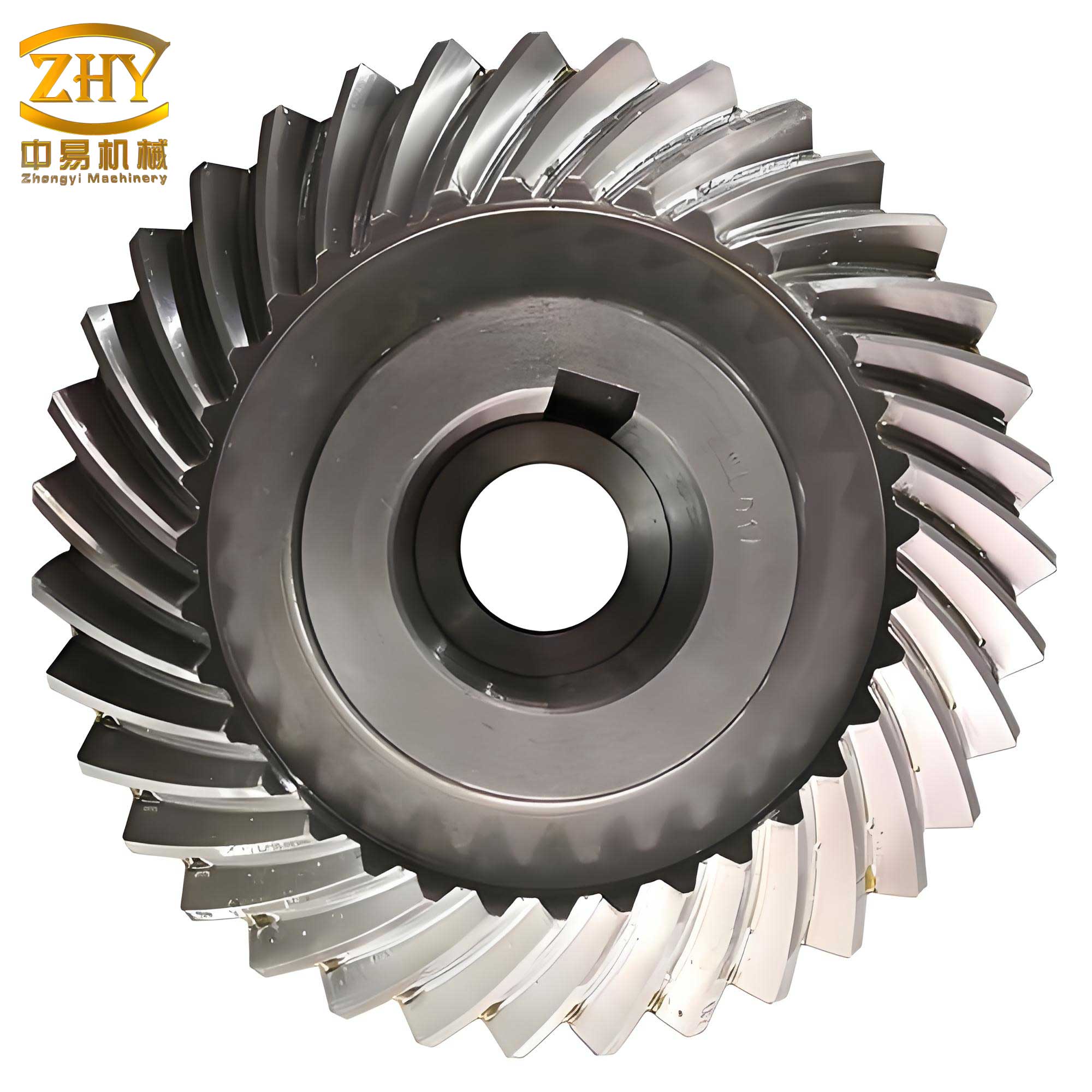
To delve deeper into the mechanics, let’s examine the basic geometric parameter transformations involved in spiral gear meshing. Typically, known parameters include the normal module \( m_n \), normal pressure angle \( \alpha_n \), number of teeth \( z_1 \) and \( z_2 \), helix angles at the reference cylinder \( \beta_1 \) and \( \beta_2 \), and modification coefficients \( x_{n1} \) and \( x_{n2} \). The fundamental calculation formulas are summarized in the following table.
| Name | Symbol | Formula |
|---|---|---|
| Transverse module | \( m_t \) | $$ m_t = \frac{m_n}{\cos \beta} $$ |
| Transverse pressure angle | \( \alpha_t \) | $$ \tan \alpha_t = \frac{\tan \alpha_n}{\cos \beta} $$ |
| Reference radius | \( r \) | $$ r = \frac{m_t z}{2} = \frac{m_n z}{2 \cos \beta} $$ |
| Base circle radius | \( r_b \) | $$ r_b = r \cos \alpha_t = \frac{m_n z \cos \alpha_t}{2 \cos \beta} $$ |
| Normal pitch | \( p_n \) | $$ p_n = \pi m_n $$ |
| Normal base pitch | \( p_{bn} \) | $$ p_{bn} = p_n \cos \alpha_n = \pi m_n \cos \alpha_n $$ |
| Transverse pitch | \( p_t \) | $$ p_t = \pi m_t = \frac{\pi m_n}{\cos \beta} $$ |
| Helix angle at base cylinder | \( \beta_b \) | $$ \sin \beta_b = \sin \beta \cos \alpha_n $$ or $$ \cos \beta_b = \frac{\cos \beta}{\cos \alpha_t} $$ |
| Tooth thickness at reference circle | \( s \) | $$ s = \frac{p_t}{2} + 2 x_t m_t \tan \alpha_t $$ where \( x_t = x_n \cos \beta \) |
| Tooth thickness at base circle | \( s_b \) | $$ s_b = s \frac{r_b}{r} + 2 r_b (\text{inv} \alpha_t – \text{inv} \alpha_{wt}) $$ |
The relationship between the meshing angle and the shaft angle is crucial. In spiral gear meshing, the line of action is the intersection of the two tangent planes to the base cylinders. Let the shaft angle be \( \Sigma \), the base helix angles be \( \beta_{b1} \) and \( \beta_{b2} \), and the transverse working pressure angles be \( \alpha_{wt1} \) and \( \alpha_{wt2} \). For gears with opposite hand helices (one left-hand, one right-hand), the meshing angle equation is:
$$ \tan \alpha_{wt1} = \frac{\sin \beta_{b2}}{\sin \beta_{b1} \cos \Sigma + \cos \beta_{b2} \sin \Sigma \cot \alpha_{wt2}} $$
$$ \tan \alpha_{wt2} = \frac{\sin \beta_{b1}}{\sin \beta_{b2} \cos \Sigma + \cos \beta_{b1} \sin \Sigma \cot \alpha_{wt1}} $$
If the helix angles are of the same hand, the signs in the equations change appropriately. The normal working pressure angle \( \alpha_{wn} \) relates to the transverse angles by \( \cos \alpha_{wn} = \cos \alpha_{wt} \cos \beta_b \). An important observation is that if the shaft angle \( \Sigma \) remains constant, the meshing angles and thus the pitch radii do not change, even if the center distance is altered. This means the pitch cylinders may not be tangent; they can be separated or intersect, a concept distinct from that in parallel-axis modified gear meshing.
For spiral gears to mesh without backlash, a specific condition must be satisfied. The center distance \( a \) is given by \( a = r_{w1} + r_{w2} \), where \( r_{w} \) are the working pitch radii. The length of the line of action \( g_\alpha \) can be derived, and the condition for zero backlash leads to the general equation:
$$ \frac{s_{b1} + s_{b2}}{p_{bn}} = \text{inv} \alpha_{wt1} + \text{inv} \alpha_{wt2} – \text{inv} \alpha_{t1} – \text{inv} \alpha_{t2} $$
This equation, combined with the meshing angle relations, forms the backbone for solving spiral gear meshing problems, including modified gears and gear processing calculations. The contact ratio, another vital parameter, is defined as the ratio of the length of the path of contact to the base pitch. For a given center distance, the contact ratio is maximized when the shaft angle \( \Sigma \) equals the sum of the working pitch cylinder helix angles \( \beta_{w1} + \beta_{w2} \). This principle is also exploited in gear machining to minimize the length of the fillet curve.
The concept of “symmetric” backlash-free meshing is particularly significant in applications like gear shaving. In symmetric meshing, the line of action passes through the common perpendicular of the two axes, i.e., through the pitch point. The symmetric meshing condition can be derived by setting the derivative of the center distance with respect to the shaft angle to zero under constant backlash-free conditions. The resulting equation is:
$$ \frac{\partial a}{\partial \Sigma} = 0 \quad \text{under} \quad \frac{s_{b1} + s_{b2}}{p_{bn}} = \text{inv} \alpha_{wt1} + \text{inv} \alpha_{wt2} – \text{inv} \alpha_{t1} – \text{inv} \alpha_{t2} $$
Solving these equations simultaneously (often using numerical methods like computers or iterative approximations) yields the transverse working pressure angles \( \alpha_{wt1} \) and \( \alpha_{wt2} \), from which other parameters like helix angles, shaft angle, and center distance can be computed. For practical engineering, approximate methods treat the meshing in the normal plane as an equivalent spur gear pair with virtual tooth numbers \( z_{vn1} = z_1 / \cos^3 \beta_{b1} \) and \( z_{vn2} = z_2 / \cos^3 \beta_{b2} \), allowing the use of standard spur gear meshing tables or curves to find parameters such as the normal working pressure angle \( \alpha_{wn} \).
The application of symmetric meshing equations is especially relevant in gear shaving processes. When a shaving cutter (a modified gear) engages with a workpiece, if the center distance deviates from the nominal value and the shaft angle is not adjusted accordingly, the line of action shifts away from the common perpendicular. This shift induces a twisting torque during shaving, adversely affecting the gear’s helix accuracy. By adjusting the shaft angle based on the actual center distance to maintain symmetric meshing, this detrimental effect can be minimized. For instance, consider a shaving cutter with parameters: \( z_c = 53 \), \( \beta_c = 15^\circ \) (right-hand), \( \alpha_n = 20^\circ \), \( m_n = 2 \, \text{mm} \), and a workpiece with \( z_w = 30 \), \( \beta_w = 30^\circ \) (right-hand). The nominal shaft angle \( \Sigma_0 = \beta_c + \beta_w = 45^\circ \). If the cutter is reground, its modification coefficient changes, altering the required center distance. To preserve symmetric meshing, the shaft angle must be recalculated. The following table illustrates how the center distance \( a \) and shaft angle \( \Sigma \) vary with the cutter’s modification coefficient \( x_{nc} \).
| \( x_{nc} \) | \( \alpha_{wn} \) (deg) | \( a \) (mm) | \( \Sigma \) (deg) |
|---|---|---|---|
| -0.2 | 20.500 | 87.950 | 45.150 |
| -0.1 | 20.250 | 87.225 | 45.075 |
| 0.0 | 20.000 | 86.500 | 45.000 |
| +0.1 | 19.750 | 85.775 | 44.925 |
| +0.2 | 19.500 | 85.050 | 44.850 |
This table demonstrates the precise adjustments needed for optimal shaving performance. Furthermore, the symmetric meshing equations facilitate the design of shaving cutters themselves. The normal working pressure angle \( \alpha_{wn} \) for the cutter-workpiece pair can be determined from charts based on the sum \( (x_{n1} + x_{n2}) \) and the virtual tooth number sum, where the cutter’s modification coefficient accounts for grinding stock allowance. Interference checks are also critical; the fillet curve generated by the shaving cutter must not interfere with the mating gear’s tooth tip. The condition to avoid such interference is:
$$ \rho_{a2} \leq \sqrt{ r_{a2}^2 – r_{b2}^2 } – a’ \sin \alpha_{w}’ + \sqrt{ r_{wc}^2 – r_{bc}^2 } $$
where \( \rho_{a2} \) is the radius of curvature at the start of the fillet on the workpiece produced by shaving, \( r_{a2} \) and \( r_{b2} \) are the tip and base radii of the mating gear, \( a’ \) and \( \alpha_{w}’ \) are the center distance and working pressure angle of the mating pair, and \( r_{wc} \), \( r_{bc} \) are the working pitch and base radii of the shaving cutter. Similarly, interference between the shaving cutter and the pre-machined fillet (e.g., from hobbing) must be avoided to prevent cutter damage, governed by:
$$ \rho_{ac} \leq \sqrt{ r_{ac}^2 – r_{bc}^2 } + \sqrt{ r_{a0}^2 – r_{b0}^2 } – a_0 \sin \alpha_{w0} $$
Here, \( \rho_{ac} \) is the fillet curvature from the previous operation, and subscripts ‘0’ refer to parameters from that operation.
In summary, the study of spiral gear meshing provides a powerful framework for understanding and optimizing gear design and manufacturing processes. The unique features of spiral gears, such as the independence of speed ratio from center distance and shaft angle, open up innovative methods for gear modification. The comprehensive set of equations for geometric transformation, meshing angles, and backlash-free conditions enables precise calculations for both power transmission and gear machining applications. Particularly, the concept of symmetric meshing proves invaluable in precision finishing operations like shaving, ensuring high accuracy by compensating for tool wear and setup variations. As gear technology advances, the principles of spiral gear meshing continue to offer profound insights, driving improvements in efficiency, accuracy, and performance across various mechanical systems. The interplay between theory and application underscores the enduring relevance of mastering these fundamental concepts in the field of gear engineering.