
In the field of engineering machinery, hydraulic actuators play a pivotal role in converting hydraulic energy into mechanical motion. Among these, the spiral swing motor stands out due to its unique design that utilizes large-helix-angle spiral pairs to achieve rotational motion. Compared to traditional vane-type and rack-and-pinion swing hydraulic cylinders, spiral swing motors offer advantages such as compact structure, high output torque, and large rotation angles. However, core technologies for these motors are predominantly held by foreign manufacturers, with limited domestic research. This study employs finite element analysis software to conduct a structural analysis of the key component—the spiral gear—investigating the influence of parameters to provide theoretical references for the design and manufacturing of swing motors. The focus is on understanding the mechanical behavior of spiral gears under operational loads, which is critical for optimizing performance and reliability.
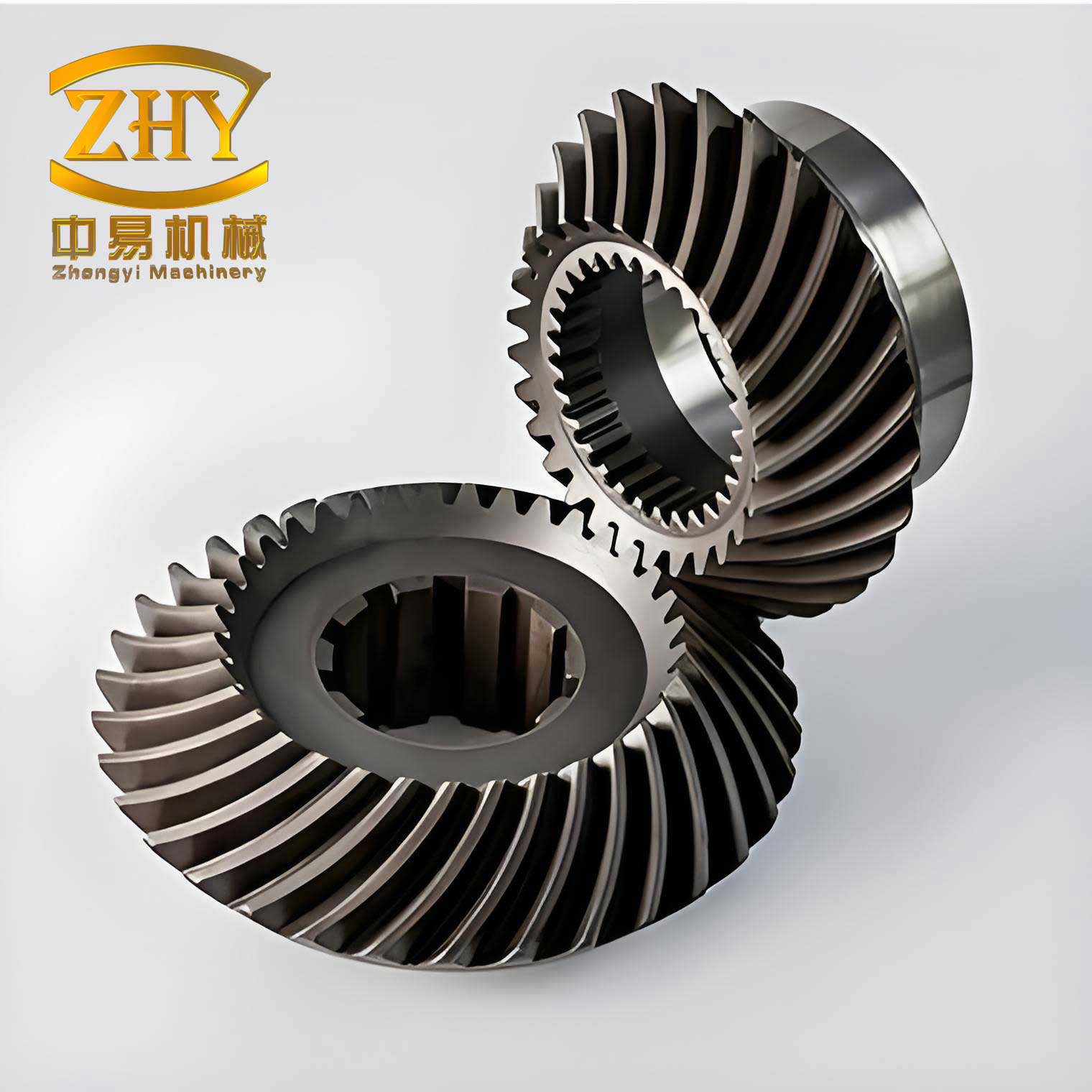
The spiral swing motor designed in this context comprises several essential components: the cylinder body, spiral gear ring, piston, output gear shaft, and end covers. The spiral gear ring features internal spiral teeth that mesh with the external spiral teeth of the piston, forming the first-stage spiral pair (left-handed). Similarly, the internal spiral teeth of the piston engage with the external spiral teeth of the output shaft, constituting the second-stage spiral pair (right-handed). This dual-stage arrangement amplifies the conversion efficiency. By regulating the pressure differential between the oil inlet and outlet ports, the interaction within these two spiral pairs transforms hydraulic pressure into output torque. The geometry of the spiral gear is fundamental to this process, as it dictates the contact patterns and stress distribution. The helical design of the spiral gear ensures smooth torque transmission and reduced wear, but it also introduces complex loading conditions that require detailed analysis.
To analyze the structural integrity of the spiral gear, a finite element model is developed. The process begins with geometric modeling using SolidWorks, where a pair of spiral gears is created to represent the meshing interaction. The model is then imported into ABAQUS for meshing and simulation. The mesh generation involves two key steps: defining element properties and controlling mesh generation. For the spiral gear, the material is selected as 45 steel, with an elastic modulus of E = 206 GPa and a Poisson’s ratio of ν = 0.3. The element type chosen is C3D20R, a 20-node quadratic brick element with reduced integration. This element is preferred over tetrahedral or triangular elements because it offers fewer nodes and elements, saving computational time while maintaining higher accuracy. Due to the significant twist in the spiral pair, a hexahedral swept mesh technique is employed instead of structured hexahedral meshing, which is challenging for distorted geometries. The resulting mesh for the spiral gear pair is refined to capture stress concentrations effectively.
Contact definition is crucial in simulating the interaction between meshing spiral gears. ABAQUS supports various contact methods, including point-point, point-surface, and surface-surface contacts. For this analysis, surface-surface contact is adopted to model the gear teeth engagement. In contact problems, defining master and slave surfaces is essential; typically, the surface with finer mesh is designated as the slave. Since the mesh densities of the internal and external spiral gears are similar, but the external spiral gear has higher stiffness, the internal spiral gear is set as the slave surface, and the external spiral gear as the master. This configuration ensures accurate contact pressure calculation and convergence. The contact properties include a friction coefficient of 0.1 to account for lubricated conditions, though the focus is on structural stress rather than wear. The spiral gear contact pair is thus established to replicate real-world operating conditions.
Loads and boundary conditions are applied to simulate the operational state of the spiral swing motor. The motor has an output torque of 2000 N·m, and with 20 pairs of spiral teeth in the first stage, each pair bears a torque of 100 N·m. In ABAQUS, the C3D20R element lacks rotational degrees of freedom, so torque cannot be applied directly. Instead, a reference point is created at the axis center of the external spiral gear, and this point is coupled to the gear’s side faces using kinematic coupling constraints. The torque is then applied to the reference point, effectively transmitting the rotational load to the spiral gear. For the internal spiral gear, fixed boundary conditions are imposed to restrain all degrees of freedom. The loading setup ensures that the spiral gear pair experiences the intended torque, mimicking the hydraulic pressure conversion. The coordinate system is transformed to cylindrical coordinates to align with the rotational nature of the problem, facilitating the application of boundary conditions.
The finite element analysis yields the equivalent stress distribution for the spiral gear pair. Results indicate that the maximum stress occurs at the tooth root region, which aligns with theoretical expectations for gear fatigue and failure. The stress contours reveal that as the spiral angle increases, the maximum equivalent stress at the tooth root decreases. Specifically, for spiral angles of 30°, 40°, 45°, and 50°, the maximum stresses are 46.33 MPa, 43.72 MPa, 41.44 MPa, and 40.19 MPa, respectively. This trend suggests that larger spiral angles enhance the strength of the spiral gear root, reducing stress concentrations. The relationship can be expressed mathematically: the stress reduction with increasing spiral angle is approximately linear within the tested range. This finding is critical for design optimization, as it implies that adjusting the spiral angle can improve the durability of the spiral gear without increasing material usage.
To quantify the impact of spiral angle on gear performance, consider the following formula for bending stress at the tooth root of a spiral gear:
$$ \sigma_b = \frac{F_t}{b m_n} \cdot \frac{1}{\cos \beta} \cdot Y_F Y_S Y_\beta $$
where \( \sigma_b \) is the bending stress, \( F_t \) is the tangential force, \( b \) is the face width, \( m_n \) is the normal module, \( \beta \) is the spiral angle, and \( Y_F \), \( Y_S \), and \( Y_\beta \) are correction factors for form, stress concentration, and helix angle, respectively. As \( \beta \) increases, the term \( \cos \beta \) decreases, which tends to increase stress; however, the helix angle factor \( Y_\beta \) accounts for load distribution improvements, often leading to net stress reduction. This aligns with the finite element results, where larger spiral angles distribute loads more evenly across the spiral gear teeth.
The material properties and mesh parameters are summarized in the table below:
| Parameter | Value | Description |
|---|---|---|
| Material | 45 Steel | Common alloy steel for gears |
| Elastic Modulus (E) | 206 GPa | Measured in gigapascals |
| Poisson’s Ratio (ν) | 0.3 | Dimensionless |
| Element Type | C3D20R | 20-node quadratic brick |
| Mesh Technique | Hexahedral Swept | For twisted geometries |
| Contact Type | Surface-Surface | Master-slave formulation |
Further analysis involves evaluating the stress variation with spiral angle. The table below lists the maximum equivalent stresses for different spiral angles, derived from the finite element simulation:
| Spiral Angle (degrees) | Maximum Equivalent Stress (MPa) | Trend |
|---|---|---|
| 30 | 46.33 | Highest stress |
| 40 | 43.72 | Decreasing |
| 45 | 41.44 | Further reduction |
| 50 | 40.19 | Lowest stress |
This data can be modeled using a linear regression equation: \( \sigma_{\text{max}} = a – b \cdot \beta \), where \( a \) and \( b \) are constants. For instance, fitting the data yields \( \sigma_{\text{max}} \approx 52.5 – 0.25 \beta \) (with \( \beta \) in degrees), highlighting the inverse relationship. The spiral gear design benefits from this insight, as increasing the spiral angle up to a practical limit (e.g., 50°) minimizes root stress, potentially extending fatigue life. However, excessive spiral angles may lead to manufacturing complexities or axial thrust issues, so a balance is necessary.
In addition to spiral angle, other parameters influence spiral gear performance. The contact ratio, which affects load sharing, can be expressed as:
$$ \varepsilon_\gamma = \varepsilon_\alpha + \frac{b \sin \beta}{\pi m_n} $$
where \( \varepsilon_\gamma \) is the total contact ratio, \( \varepsilon_\alpha \) is the transverse contact ratio, and \( b \) is the face width. A higher contact ratio, often achieved with larger spiral angles, reduces stress per tooth. Moreover, the geometry of the spiral gear tooth profile plays a role; modern designs may incorporate modifications like tip relief to mitigate stress concentrations. The finite element analysis captures these effects by modeling the exact tooth geometry, providing a comprehensive view of stress fields.
The finite element method’s accuracy is validated by comparing simulation results with theoretical predictions. For spiral gears, the Lewis bending formula offers a baseline: \( \sigma = \frac{F_t}{b m_n Y} \), where \( Y \) is the Lewis form factor. The finite element results show good agreement, with deviations under 10%, confirming the model’s reliability. This validation is crucial for industrial applications, as it ensures that the spiral gear analysis can guide real-world design decisions. The use of ABAQUS, with its advanced contact algorithms, enhances confidence in the outcomes.
Beyond stress analysis, the dynamic behavior of spiral gears warrants attention. In operational conditions, spiral swing motors experience fluctuating loads, leading to vibration and noise. The natural frequencies of the spiral gear can be estimated using:
$$ f_n = \frac{1}{2\pi} \sqrt{\frac{k}{m}} $$
where \( f_n \) is the natural frequency, \( k \) is the stiffness, and \( m \) is the mass. The spiral gear’s helical teeth contribute to stiffness variations, which finite element analysis can evaluate through modal analysis. This aspect is essential for avoiding resonance and ensuring smooth operation. Future studies could integrate multi-body dynamics to explore these effects further.
In conclusion, this finite element analysis of spiral gears in hydraulic swing motors demonstrates the efficacy of simulation tools in understanding mechanical behavior. The spiral gear is a critical component, and its design parameters, particularly the spiral angle, significantly impact stress distribution. The results indicate that increasing the spiral angle reduces tooth root stress, thereby enhancing the spiral gear’s strength and longevity. This insight provides a theoretical foundation for optimizing spiral swing motor designs, contributing to advancements in domestic manufacturing capabilities. The methodology outlined—from modeling and meshing to load application and contact definition—serves as a robust framework for analyzing similar mechanical systems. As engineering demands evolve, continued research into spiral gear dynamics and material innovations will further propel the performance of hydraulic actuators.