
In my extensive experience with power transmission systems, the application of spiral gears, specifically crossed helical gears, has always presented a unique set of challenges and advantages. These components are crucial for transmitting motion between non-parallel, non-intersecting shafts, offering significant design flexibility regarding shaft angles and center distances. The point contact nature of spiral gear meshing, however, inherently limits their load-carrying capacity and makes them susceptible to surface wear, particularly in demanding power transmission roles. This narrative details a thorough investigation my team and I conducted into a severe wear failure of a spiral gear pair, outlining our analytical process, findings, and the successful corrective actions implemented.
The specific application involved a spiral gear set functioning as a power take-off for a regulator system within a larger mechanical assembly. The driving spiral gear was mounted on a reducer rotor, engaging with a driven spiral gear to supply hydraulic power for control and lubrication. During initial operational trials, we observed significant surface degradation on the gear teeth. The driven gear exhibited severe abrasive wear, while the driving gear showed noticeable scoring marks. This was a critical failure, as a similar spiral gear arrangement in a predecessor model had performed reliably over long-term operation without such issues. Our immediate task was to isolate the root cause, given that all geometrical parameters, alignment conditions, and lubrication provisions were verified to be identical to the proven legacy design.
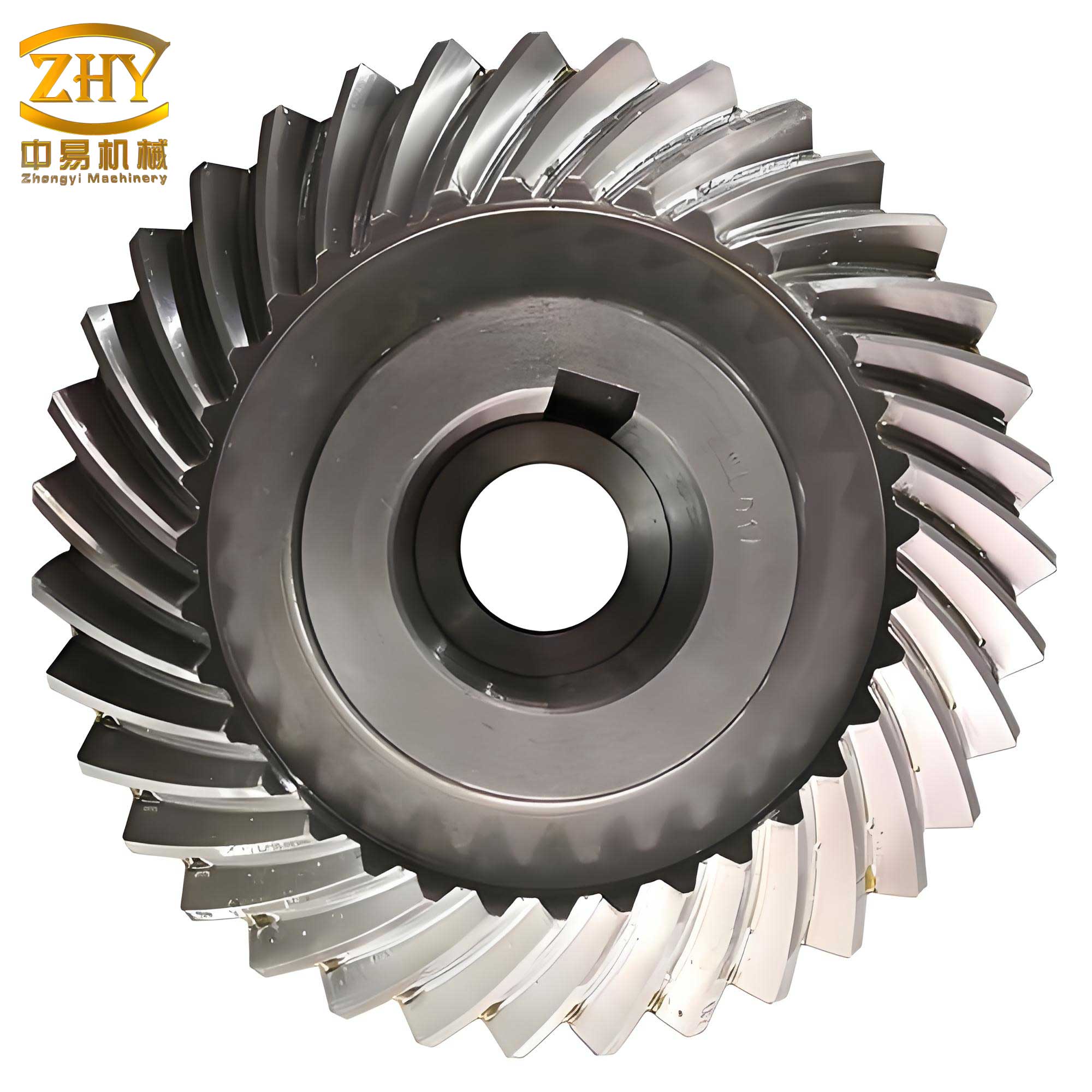
Our investigation pivoted to factors not thoroughly documented from the legacy design, primarily material specifications and heat treatment processes. We hypothesized that a discrepancy in material hardness or subsurface properties was the most plausible culprit for the accelerated spiral gear wear. The failed driving gear was manufactured from 42CrMo steel and subjected to a quenching and tempering (调质) process. The driven gear was a cast tin bronze (ZCuSn10P1) produced via sand casting. In contrast, upon forensic examination of the legacy spiral gears, we discovered a stark difference: the driving gear had a case-hardened surface with a significantly higher hardness, and the bronze driven gear was produced using centrifugal casting. This prompted a systematic analysis divided into two pillars: comparative metallurgical inspection and advanced computational stress analysis.
The first pillar involved a detailed comparison of heat treatment outcomes and material hardness. The results are summarized in the table below, which clearly illustrates the performance gap.
| Gear Component | Design Variant | Material & Process | Surface Hardness Measurement | Inferred Surface Fatigue Limit (σHlim) |
|---|---|---|---|---|
| Driving Spiral Gear | Legacy (Successful) | Case-Hardening (e.g., Carburizing & Quenching) | >55 HRC | Approx. 425 MPa |
| Current (Failed) | 42CrMo, Quenched & Tempered | ~280 HB (approx. 29 HRC) | Approx. 199 MPa | |
| Driven Spiral Gear | Legacy (Successful) | ZCuSn10P1, Centrifugal Casting | >110 HB | Dependent on mating gear |
| Current (Failed) | ZCuSn10P1, Sand Casting | ~80 HB | Dependent on mating gear |
The surface fatigue limit σHlim is a critical material property indicating the maximum contact stress a gear surface can endure for a specified life without pitting or wear. The data clearly shows that the current spiral gear pair’s surface hardness and, consequently, its fatigue limit were substantially lower than those of the legacy pair. This finding strongly suggested that the operational contact stresses were exceeding the material’s capacity, leading to progressive surface wear. The second pillar of our investigation aimed to quantify these contact stresses through Finite Element Analysis (FEA).
We constructed a detailed 3D model of the spiral gear pair for finite element simulation. The gear parameters were: driving gear teeth (Z1)=23, driven gear teeth (Z2)=35, normal module (mn)=2.0 mm. A segment of the gear body containing multiple teeth was extracted to reduce computational cost while maintaining accuracy. The model was meshed primarily with hexahedral elements, with localized refinement in the potential contact zones to capture high stress gradients accurately. Contact analysis was configured to model the actual meshing condition; based on a calculated transverse contact ratio of approximately 1.83, two pairs of teeth were set to be in simultaneous contact. Boundary conditions were applied as follows: the driving spiral gear shaft was constrained with cylindrical supports allowing rotation, and a torque of 3.43 N·m was applied. The driven spiral gear was fully constrained. The contact stress distribution was solved using a static structural analysis module.
The fundamental contact stress for gears can be described by the Hertzian contact theory. For a point contact scenario like that in spiral gears, the maximum contact pressure (p0) can be expressed as:
$$ p_0 = \frac{3F}{2\pi ab} $$
where F is the normal load, and a and b are the semi-major and semi-minor axes of the elliptical contact area, respectively. These axes depend on the relative radii of curvature of the contacting tooth surfaces at the point of contact. The von Mises stress or direct contact pressure from FEA provides a more comprehensive picture considering the complex 3D geometry. Our FEA results revealed that the contact stress was highly localized, forming an elliptical pressure zone on the tooth flank. The maximum calculated contact stress value was approximately 335 MPa. Comparing this with the fatigue limits from Table 1 (199 MPa for the failed pair), it was evident that the operating stress was about 68% higher than the material’s endurance limit. This quantitative finding confirmed our hypothesis: the spiral gear wear was primarily driven by inadequate surface strength, making the material susceptible to plastic deformation and abrasive wear under cyclic loading.
The path to a solution was clear: we needed to enhance the surface durability of the spiral gear pair to withstand the calculated contact stresses. Drawing from the legacy design’s success, we implemented the following corrective measures for the spiral gear set:
- Driving Spiral Gear: The material was changed to 20CrMnTi, a low-carbon alloy steel ideal for case hardening. The gear was then subjected to carburizing followed by quenching and low-temperature tempering. This process creates a hard, wear-resistant surface layer (with hardness >58 HRC) while maintaining a tough, ductile core to handle bending loads.
- Driven Spiral Gear: The material remained ZCuSn10P1 tin bronze, but the manufacturing process was changed from sand casting to centrifugal casting. This technique yields a denser, more homogeneous microstructure with fewer casting defects, improved mechanical properties, and generally higher surface hardness and fatigue resistance.
The principle behind this material pairing is to create a favorable combination where the harder steel gear runs against a softer but conformable bronze gear, which can embed abrasive particles and exhibit good run-in behavior. The key is ensuring both materials have sufficient intrinsic strength for the application.
To validate the effectiveness of our modifications, a rigorous 500-hour endurance test was conducted on the full assembly incorporating the redesigned spiral gears. The test profile was designed to be more severe than normal operation, including 100 cycles of rapid high-low power transitions. In these transitions, the speed of the driving spiral gear would change from 1930 rpm to 2900 rpm (and vice versa) within seconds, subjecting the gears to significant dynamic loads and shock. After completing the 500-hour test, the assembly was disassembled for inspection. The spiral gear teeth were visually examined and meticulously measured.
| Test Phase | Driven Spiral Gear Tooth Thickness | Driving Spiral Gear Tooth Thickness |
|---|---|---|
| After Factory Run-in | 2.62 | 2.68 |
| After 300 Hours | 2.62 | 2.68 |
| After 400 Hours | 2.62 | 2.68 |
| After 500 Hours | 2.62 | 2.68 |
The visual inspection showed no signs of abnormal wear, pitting, or scoring on the flanks of either spiral gear. The tooth thickness measurements, as tabulated above, remained constant throughout the entire test duration, confirming that no measurable material loss had occurred. This was in stark contrast to the initial failure. The successful test outcome unequivocally validated our root cause analysis and the chosen corrective strategy for the spiral gear pair.
In conclusion, this investigation into the premature failure of a spiral gear drive underscores the critical importance of material selection and processing in gear design, especially for point-contact geometries like spiral gears. Our systematic approach, combining forensic metallurgical analysis with advanced computational stress simulation using FEA, successfully identified insufficient surface hardness as the primary root cause of the wear. The operational contact stress, calculated to be approximately 335 MPa, exceeded the material’s fatigue limit of 199 MPa. The remedy, involving upgrading the driving spiral gear to a carburized and hardened state and manufacturing the driven spiral gear via centrifugal casting, proved entirely effective. The enhanced spiral gear set demonstrated exceptional durability under prolonged and severe testing, with no detectable wear. This case serves as a potent reminder that for critical components like spiral gears, specifying the material alone is insufficient; the precise heat treatment or manufacturing process must be meticulously defined and controlled to achieve the required performance and reliability. The spiral gear, while a simple component in concept, demands a holistic engineering approach to realize its full potential in power transmission applications.
Reflecting on this project, the role of finite element analysis was indispensable. It allowed us to move beyond qualitative assessments and obtain a quantitative measure of the stress state within the complex spiral gear mesh. The contact stress formula $$ \sigma_H = Z_E \sqrt{ \frac{F_t}{b d_1} \cdot \frac{u \pm 1}{u} \cdot K_A K_V K_{H\beta} K_{H\alpha} } $$, often used for cylindrical gears, provides a standardized calculation. However, for the unique crossed-axis geometry of spiral gears, 3D FEA is far more accurate for capturing the true localized contact conditions. Furthermore, understanding the relationship between hardness (H) and yield strength (σy), often approximated by $$ \sigma_y \approx 3.5 \times H $$ (for steels in MPa, with H in Vickers or converted), helped us appreciate why increasing surface hardness was so effective. The new case-hardened surface on the driving spiral gear likely has a yield strength exceeding 2000 MPa, well above the 335 MPa contact stress, preventing plastic flow and wear initiation. For the bronze driven spiral gear, the centrifugal casting process improves its fatigue strength by reducing porosity and creating a finer grain structure, which can be related to the Hall-Petch relationship: $$ \sigma_y = \sigma_0 + k_y d^{-1/2} $$, where a smaller grain size (d) increases yield strength. This comprehensive understanding of materials, processes, and mechanics is essential for designing robust spiral gear systems.
The broader implications of this work extend to many applications utilizing spiral gears or similar point-contact transmissions. In aerospace actuators, marine propulsion auxiliaries, or precision instrumentation, where space constraints or specific shaft angles mandate the use of spiral gears, ensuring their longevity is paramount. Our findings emphasize that designers must not only calculate geometric parameters but also perform a thorough verification of contact stresses against the permissible limits for the chosen material pair under the specified processing conditions. A proactive design validation loop should include FEA of the spiral gear contact and a strict protocol for material and process qualification. Future work could explore advanced surface engineering techniques like nitriding or physical vapor deposition (PVD) coatings for spiral gears to further push the boundaries of their power density and wear resistance. Additionally, developing more sophisticated analytical models specifically tailored for the wear prediction of spiral gears under mixed lubrication regimes would be a valuable contribution to the field. Ultimately, the humble spiral gear, when properly engineered, remains a versatile and reliable solution for non-parallel shaft drives.