
The spiral bevel gear is a critical foundational component for transmitting motion between intersecting axes. Due to its advantages of high overlap ratio, strong load-bearing capacity, high transmission efficiency, smooth operation, and low noise, it is extensively used in automobiles, aircraft, machine tools, and various mechanical products. The surface quality of the gear teeth directly influences transmission performance, fatigue life, and noise levels. Pulse Electrochemical Finishing (PECF) is an advanced non-traditional machining process capable of significantly reducing surface roughness and improving surface integrity. This article explores the fundamental principles, key influencing parameters, application methodology for spiral gears, and critical implementation aspects of this promising technology.
The core principle of PECF is based on controlled anodic dissolution. During processing, the workpiece (anode) and a shaped tool (cathode) are immersed in an electrolyte and connected to a pulsed power supply. When pulsed current is applied, metal ions are dissolved from the anode surface according to Faraday’s law of electrolysis. The volume of material removed, V, can be expressed as:
$$ V = \eta \omega I t $$
where $\eta$ is the current efficiency, $\omega$ is the volumetric electrochemical equivalent of the workpiece material (cm³/A·h), $I$ is the current (A), and $t$ is the machining time (h). The localized dissolution rate, or etch rate $V_a$, is proportional to the current density $i$ (A/cm²):
$$ V_a = \eta \omega i $$
In PECF, the cathode is designed to conform to the desired final surface geometry but is maintained at a small, controlled distance from the workpiece, creating an inter-electrode gap. A pressurized, non-linear electrolyte (e.g., NaNO₃ solution) is flushed through this gap to remove dissolution products and heat. The use of pulsed current, as opposed to direct current, introduces periodic relaxation, improves electrolyte refreshment in the gap, and allows for better process control.
The smoothing action in PECF occurs through two simultaneous phenomena: macro-leveling and micro-leveling (brightening). Macro-leveling results from the non-uniform distribution of current density across a rough surface. Peaks on the workpiece surface are closer to the cathode than valleys, leading to a higher current density and faster dissolution at the peaks, thereby flattening the surface profile. The removal rate at a point is inversely proportional to the local gap, $\Delta$:
$$ V_a = \eta \omega K \frac{U_R}{\Delta} $$
where $K$ is the electrolyte conductivity and $U_R$ is the ohmic voltage drop in the gap. This relationship drives the preferential removal of high points.
Micro-leveling or brightening is a surface-kinetics controlled process that produces a shiny, mirror-like finish. It is associated with anodic dissolution under mass-transport controlled conditions, often above a limiting current density. Under specific electrochemical conditions (high potential, appropriate electrolyte), a thin, resistive salt film can form on the anode surface. This film leads to a limiting current plateau. Dissolution above this limit, often in the transpassive or super-passive region for some electrolytes like NaNO₃, results in uniform, selective removal at the micro-crystalline level, yielding a bright surface. The transition time $\tau$ to form this film is inversely related to the current density. Pulsed current exploits this by using short, high-energy pulses where the pulse-on time is comparable to $\tau$, enabling brightening at lower average currents.
The quality and efficiency of PECF are governed by a complex interplay of numerous process parameters. Understanding their influence is crucial for optimizing the process for spiral gear finishing.
| Process Parameter | Influence on PECF and Surface Quality |
|---|---|
| Current Density ($i$) | Fundamentally controls dissolution rate ($V_a \propto i$). Below a critical (limiting) value, results in a matte, etched surface. Above this value, enables micro-leveling and a bright finish. Excessively high density can cause non-uniform dissolution and pitting. |
| Electrolyte Composition | Determines passivation behavior and machining accuracy. Neutral salts like NaNO₃ or NaClO₃ are common. NaNO₃ promotes formation of a protective passive film on surfaces with larger gaps, reducing stray etching and improving dimensional control (“non-linear” behavior). |
| Workpiece Material | Alloys with hard, non-conductive phases (e.g., Fe₃C in high-carbon steel) can leave insoluble residues on the finished surface, limiting the achievable smoothness. Homogeneous materials yield better results. |
| Inter-Electrode Gap ($\Delta$) | A smaller initial gap increases dissolution rate and macro-leveling efficiency ($V_a \propto 1/\Delta$). However, a very small gap hinders electrolyte flow and debris removal, risking instability. A gap of 0.2-0.3 mm is often optimal. |
| Pulse Parameters (Frequency, Width, Duty Cycle) | Higher frequencies improve surface finish by promoting more uniform gap conditions. Narrow pulse widths and appropriate off-times aid in electrolyte renewal and heat dissipation, improving precision and surface quality. |
| Cathode Surface Topography | The micro-geometry of the cathode surface can be replicated onto the anode workpiece, a phenomenon known as error replication. A smooth cathode surface is essential for achieving a fine finish on the spiral gear. |
The influence of cathode surface roughness ($R_a$) on workpiece finish is particularly important for precision applications like gear finishing. The “tip effect” favors leveling, while “error replication” degrades it. The degree of replication depends on the relative size of the cathode’s surface asperities ($\delta$) compared to the machining gap ($\Delta$). Analysis shows that the replicated error $\lambda$ can be approximated by:
$$ \lambda = C \cdot t \left( \frac{1}{\Delta} – \frac{1}{\Delta + \delta} \right) $$
where $C$ is a constant for given conditions. This implies that for a given machining time $t$, the error $\lambda$ decreases as the gap $\Delta$ increases or the cathode roughness $\delta$ decreases. Experimental studies confirm that when the inter-electrode gap exceeds approximately 0.3 mm, the influence of the cathode’s微观形貌 on the final workpiece surface becomes negligible. For smaller gaps, a cathode with a surface roughness $R_a$ below 0.2 µm is recommended to minimize error replication. Furthermore, employing a moving cathode (as in the following application mode) helps to average out and mitigate this effect.
Applying PECF to complex geometries like spiral gears requires a specialized approach. The most viable method is to adapt the existing generation kinematics of spiral gear cutting machines. Two primary machining methods are employed in industry: the Formate (non-generated) method for the gear and the Generate (continuous indexing) method for the pinion. PECF can be adapted to simulate these motions.
For the gear (Formate method), the cathode tool, shaped to the conjugate tooth form, is mounted on a rotating cutter head. The gear workpiece indexes stationarily. The cathode teeth, electrically insulated from the machine structure, pass over the gear tooth flanks with a preset uniform gap. Electrolyte is supplied through channels in the cathode holder. This setup allows for simultaneous finishing of both flanks of multiple tooth spaces. For the pinion (Generate method), a similar rotating cathode head is used, but with continuous coordinated motion (generation) between the cutter head (simulating a imaginary generating gear) and the pinion workpiece. This replicates the rolling contact of meshing gears to finish the complex curvilinear pinion tooth surfaces.
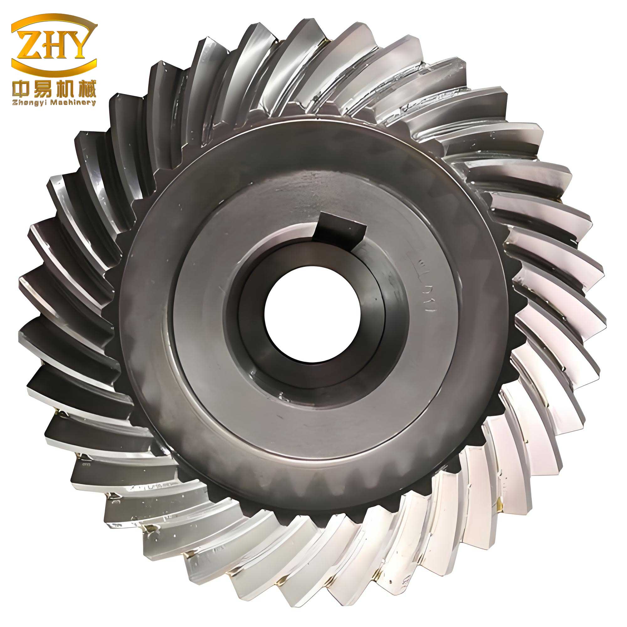
The design of the cathode tool and its system is the cornerstone of implementing PECF for spiral gears. Key considerations include:
- Machine Tool Adaptation: A conventional spiral gear cutting machine (e.g., a modified Gleason-type cutter) must be adapted. The spindle is modified to be hollow, allowing for the passage of insulated power cables and electrolyte supply tubes to the rotating cathode head. Critical components like the workpiece fixture and spindle bearings must be protected from electrolyte exposure or corrosion.
- Flow Field Design: Uniform electrolyte flow in the narrow, complex gap between the spiral gear tooth and cathode is vital. Inadequate flow leads to stagnation, overheating, and uneven dissolution. Computational modeling and experimental visualization are used to design cathode geometries with multiple, strategically placed electrolyte inlets and outlets to ensure complete and uniform coverage of the active tooth flank area.
- Cathode Structure: The cathode is typically a composite structure. The active conductive part, made from corrosion-resistant materials like stainless steel or titanium, is shaped to the desired tooth form with a slight offset to account for the finishing gap. It is embedded in or attached to an insulating holder (e.g., epoxy resin or ceramic) that also contains the internal electrolyte channels. The number of cathode teeth on the head is optimized to balance finishing efficiency, flow distribution, and tool complexity.
- Insulation and Power Delivery: Complete electrical insulation between the cathode assembly and the machine body is mandatory. Power is delivered via slip rings or rotary electrical connectors to the rotating head. Electrolyte is supplied through rotary unions.
A significant practical challenge in implementing PECF on a machine tool is the prevention of corrosion on non-processed areas of the workpiece and, critically, on the machine tool itself. The electrolyte (e.g., aqueous NaNO₃) is corrosive to ferrous components. Since complete sealing of the complex gear machining workspace is difficult, corrosion inhibitors must be added to the electrolyte.
Experimental studies evaluate inhibitors based on their corrosion protection effectiveness and their minimal impact on the electrolyte’s conductive properties. The conductivity, central to the process as seen in $V_a = \eta \omega K U_R / \Delta$, must not be severely degraded. Tests involve immersing steel coupons in electrolyte with different inhibitors and concentrations. Corrosion rates are assessed visually and gravimetrically. The electrolyte’s伏安特性 (current-voltage relationship) is measured to evaluate conductivity changes.
A suitable inhibitor, such as certain salt-based organic compounds, at a concentration of 1-2 wt.%, can provide adequate corrosion protection for machine components during processing without significantly altering the electrolyte’s conductivity or the fundamental PECF process dynamics. Post-processing, a standard rust preventive applied to the finished spiral gear provides long-term storage protection.
In conclusion, Pulse Electrochemical Finishing presents a highly promising technology for the precision finishing of hardened spiral gear surfaces. Its ability to substantially reduce surface roughness (often achieving mirror-like finishes), improve surface integrity, and process hard materials without introducing mechanical stresses or tool wear addresses key limitations of conventional methods like grinding or hard cutting. The fundamental principles of anodic dissolution, macro- and micro-leveling, and the influence of key parameters like current density, gap, and electrolyte provide a scientific basis for process control. The adaptation of the technology to spiral gears through simulated generation kinematics and specialized cathode tooling design is technically feasible. Overcoming practical challenges such as uniform flow field design and machine corrosion through inhibitor use is essential for industrial implementation. Future research directions include the development of CNC-based PECF systems for flexible correction of heat treatment distortions and contact pattern optimization, as well as the exploration of hybrid processes combining PECF with gentle mechanical abrasion for even higher efficiency and surface quality. Advancing this technology holds significant potential for enhancing the performance, durability, and noise characteristics of spiral gears across critical industries such as automotive, aerospace, and energy.