
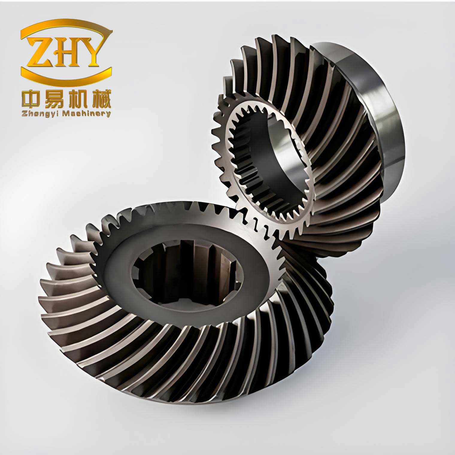
In the study of gear transmission, particularly for crossed-axis drives, the concept of spiral gears is fundamental. When two cylindrical helical gears mesh with non-parallel axes, this configuration is termed spiral gear meshing. Specifically, gears with tooth surfaces shaped as involute helicoids in crossed-axis drives are referred to as involute spiral gears. During meshing, the tooth surfaces of two involute spiral gears contact at only a single point at any given instant. The trajectory of these contact points on a tooth surface over the course of transmission is known as the contact trace, also referred to as the normal meshing tooth profile. The contact trace is a critical principle in understanding how tooth surfaces are formed in processes such as hobbing, shaving, gear shaping, and worm wheel grinding. Errors in the contact trace are essential for analyzing manufacturing inaccuracies in these gear machining techniques and serve as a primary inspection item in the tolerance system for involute spiral gear transmissions.
From a meshing perspective, during spiral gear transmission, the path of contact points in a stationary coordinate system fixed to the machine frame is called the line of action. As the gears rotate, the tooth surface intersects this line at a series of points, and the locus of these intersections on the tooth surface constitutes the contact trace. The line of action is a straight line simultaneously tangent to the base cylinders of both gears. Its direction within the tangent plane to the base cylinder can be illustrated geometrically. Consider a base cylinder of one spiral gear in the pair; the tangent plane to the base cylinder at the pitch point contains the line of action. The angle between this line and the gear axis is complementary to the base helix angle. Notably, even if the center distance between the mating gears changes, the angle between the line of action and the gear axis remains constant, meaning that the direction of the line of action in the tangent plane is solely determined by the base helix angle.
To establish a coordinate system for analysis, let the gear axis be the z-axis. Define a plane parallel to the tangent plane of the base cylinder, with the x-axis passing through the pitch point. As the gear rotates about the z-axis, the intersection points of the tooth surface with the line of action trace out the contact trace. Since the line of action’s direction is fixed relative to the base cylinder, the shape of the contact trace depends only on the base circle diameter and the base helix angle of the involute spiral gear. For straight spur gears, the contact trace simplifies to the transverse involute curve. In practice, when using a worm as a measuring element for single-flank composite testing via the inter-tooth method, motion errors induced by contact trace deviations can be captured. Considering the direction of error transmission, contact trace errors should be measured along the line of action. However, dedicated instruments for单项测量 (single-item measurement) of contact traces are not yet widely available.
In motion analysis for contact trace measurement, assume a starting point for measurement on the contact trace. As the gear rotates by an angle $\theta$, the tooth profile moves from its initial position to a new one, intersecting the line of action at a specific point. This leads to the requirement that a specialized contact trace measuring instrument must execute the following motions:
- An adjustment motion to set the radial position of the probe relative to the gear, corresponding to movement along the x-direction in the coordinate system, ensuring the probe operates within the tangent plane of the base cylinder.
- A rotational motion of the gear about its axis.
- A motion of the probe along the x-direction within the tangent plane, synchronized with gear rotation.
- An axial motion of the probe along the z-direction, following a specific functional relationship with the gear’s rotation angle.
Denote the base radius as $r_b$ and the base helix angle as $\beta_b$. For a gear rotation $\theta$, the developed length on the base cylinder is $r_b \theta$. Based on geometric relationships, the probe displacements can be derived. Let the coordinates of the contact point in the system be $(x, y, z)$. The motion equations for the contact trace measuring instrument are as follows:
$$x = r_b \theta \sin \beta_b – r_b \theta \tan \beta_b \cos \beta_b$$
$$y = r_b \theta \cos \beta_b + r_b \theta \tan \beta_b \sin \beta_b$$
$$z = r_b \theta \tan \beta_b$$
Here, $x$ and $y$ represent the coordinates in the tangent plane, and $z$ is the axial coordinate. These equations govern the relative motion between the probe and the gear to accurately trace the contact path. On computer-controlled three-coordinate measuring machines equipped with rotary tables, programming based on these equations enables contact trace measurement. For instruments operating on mechanical generation principles, the传动机构 (transmission mechanism) can be designed accordingly using these formulas.
When considering specific gear measuring instruments, such as the 上名-type gear measuring仪, adjustments are necessary for contact trace measurement. In such instruments, if the rolling disk size does not match the theoretical base circle dimensions, the probe tip relative to the tooth surface will not follow the transverse involute but rather a helical involute curve. The key question is: at what rolling disk size does the probe trace exactly the contact trace? Due to instrumental constraints, limitations exist for contact trace measurement on these devices.
In the 上名-type instrument, the probe’s vertical motion is designed as half the horizontal displacement of the straight edge. From the motion equations, the required vertical motion of the probe is $r_b \theta \tan \beta_b$. Equating this with the instrument’s design yields a condition linking the rolling disk diameter $D$ to the base circle parameters. Specifically, the horizontal compensation motion of the probe relative to the straight edge must be consistent with the derived equations. Through kinematic analysis, the rolling disk diameter $D$ for contact trace measurement should satisfy:
$$D = d_b \left(1 + \tan^2 \beta_b\right)$$
where $d_b$ is the base diameter. Verification via the horizontal motion confirms this relationship. According to the instrument manual, the adjustment angle $\beta_0$ is calculated as $\beta_0 = \arctan(\tan \beta / \cos \alpha_n)$, where $\beta$ is the helix angle and $\alpha_n$ is the normal pressure angle. For spiral gears, since the helix angle at the reference circle typically does not exceed 45°, the base helix angle $\beta_b$ is less than 45°, leading to $\tan \beta_b < 1$. Thus, the instrument’s optical scale adjustment must account for this.
For right-hand spiral gears, the compensation motion of the probe horizontally is $r_b \theta \tan \beta_b \cos \beta_b$, which, per the manual, aligns with the straight edge motion. The total horizontal displacement combines this with the straight edge movement, resulting in the expression $r_b \theta \sin \beta_b$. This matches the theoretical requirement from the motion equations, validating the disk size formula.
The difference between the selected rolling disk diameter and the base diameter should be minimal for accurate measurement. This imposes restrictions on the measurable base helix angles. Solving the inequality derived from the instrument’s kinematics gives the permissible range for $\beta_b$ when measuring contact traces on the 上名-type instrument. The constraints are summarized in the table below:
| Gear Type | Permissible Base Helix Angle $\beta_b$ Range |
|---|---|
| Right-Hand Spiral Gears | $0^\circ \leq \beta_b < 30^\circ$ |
| Left-Hand Spiral Gears | $0^\circ \leq \beta_b < 35^\circ$ |
These ranges ensure that the instrument’s fixed relationship between straight edge movement and probe vertical motion does not引入 significant errors. Additionally, the probe force direction must be perpendicular to the contact line during measurement, so that the sensor detects contact trace errors along the line of action direction.
Expanding on the motion analysis, the contact trace for involute spiral gears can be expressed parametrically. Let $u$ be a parameter along the tooth surface. The tooth surface coordinates for a right-hand spiral gear are given by:
$$x = r_b (\cos \theta + \theta \sin \theta) \cos \beta_b – r_b (\sin \theta – \theta \cos \theta) \sin \beta_b$$
$$y = r_b (\cos \theta + \theta \sin \theta) \sin \beta_b + r_b (\sin \theta – \theta \cos \theta) \cos \beta_b$$
$$z = p \theta$$
where $p$ is the helix parameter, $p = r_b \tan \beta_b$. The contact trace is derived by intersecting this surface with the line of action plane. The intersection condition leads to the earlier motion equations. This parametric form is useful for simulation and error analysis.
In practical applications, measuring the contact trace of spiral gears is crucial for quality control. For instance, in automotive transmissions, spiral gears are used in crossed-axis configurations to achieve compact designs. Errors in contact trace can lead to noise, vibration, and reduced efficiency. Therefore, developing accurate measurement methods is essential. The motion equations provided enable the design of dedicated contact trace measuring machines or the adaptation of existing multi-axis systems.
To delve deeper, consider the generation of spiral gears via hobbing. The hob essentially simulates a mating gear, and the contact trace during generation influences the final tooth geometry. By measuring the contact trace on finished gears, deviations from the theoretical path can be correlated with machine tool errors, such as misalignments or feed inaccuracies. This analysis aids in process optimization.
Another aspect is the influence of tooth modifications on the contact trace. For spiral gears, profile and lead modifications alter the contact path. Measuring the actual contact trace helps verify if modifications are applied correctly. The motion equations can be extended to include modification functions. For example, if a crown modification is applied, the $z$-displacement might include a quadratic term:
$$z = r_b \theta \tan \beta_b + C \theta^2$$
where $C$ is the modification coefficient. This complicates the measurement but can be handled with advanced controllers.
Regarding instrument limitations, the 上名-type gear measuring仪 has fixed kinematic chains, which restrict the range of measurable spiral gears. For gears with high base helix angles, the required disk sizes may not be physically available, or the compensation motions may exceed instrument ranges. Table 2 lists additional constraints based on gear module and size:
| Module Range (mm) | Max Base Diameter (mm) | Compatible $\beta_b$ Range |
|---|---|---|
| 1–5 | 150 | $0^\circ–40^\circ$ |
| 5–10 | 300 | $0^\circ–30^\circ$ |
| 10–20 | 500 | $0^\circ–25^\circ$ |
These limitations highlight the need for versatile measurement systems. Modern coordinate measuring machines (CMMs) with rotary axes offer a solution. By programming the motion equations into the CMM controller, contact traces can be measured for a wide range of spiral gears without dedicated hardware. The probe path is controlled in real-time, and data is collected for error evaluation.
Error sources in contact trace measurement include probe alignment errors, rotational inaccuracies, and thermal effects. To mitigate these, calibration procedures are necessary. For example, the base circle radius $r_b$ must be precisely known. It can be calculated from gear parameters:
$$r_b = \frac{m_n z}{2 \cos \beta} \cos \alpha_t$$
where $m_n$ is the normal module, $z$ is the number of teeth, $\beta$ is the helix angle at the reference circle, and $\alpha_t$ is the transverse pressure angle. The base helix angle $\beta_b$ is related by:
$$\sin \beta_b = \sin \beta \cos \alpha_n$$
These relationships ensure accurate setup.
In conclusion, the contact trace of involute spiral gears is a fundamental aspect of their meshing behavior. Its measurement requires precise motion control based on derived kinematic equations. While specialized instruments exist, they have limitations in terms of allowable gear parameters. With advancements in multi-axis measuring systems, flexible and accurate contact trace measurement is achievable, aiding in the quality assurance of spiral gear transmissions. Future work could focus on real-time error compensation and integration with digital twins for smart manufacturing.
To further elaborate, the mathematical foundation of spiral gear contact traces stems from differential geometry. The tooth surface of an involute spiral gear is a ruled surface generated by the involute curve in the transverse plane and the helix along the axis. The parametric equations are:
$$ \mathbf{r}(u, v) = \begin{bmatrix} r_b (\cos u + u \sin u) \cos \beta_b – r_b (\sin u – u \cos u) \sin \beta_b \\ r_b (\cos u + u \sin u) \sin \beta_b + r_b (\sin u – u \cos u) \cos \beta_b \\ r_b u \tan \beta_b \end{bmatrix} + v \begin{bmatrix} -\sin \beta_b \\ \cos \beta_b \\ 0 \end{bmatrix} $$
where $u$ is the involute parameter and $v$ is the ruling parameter. The contact trace is the curve on this surface that satisfies the meshing equation with the mating gear. For a crossed-axis setup with shaft angle $\Sigma$, the meshing equation leads to a specific relationship between $u$ and $v$, which can be solved numerically.
In measurement practice, the probe must follow this curve. The motion equations provided earlier are a simplified version for practical implementation, assuming the probe tip is a point and the gear is rotated continuously. For discrete point measurement, as on a CMM, the equations are sampled at incremental $\theta$ values.
Another important consideration is the effect of misalignment on the contact trace. If the gear axes are not perfectly positioned, the actual contact path deviates from the theoretical one. By measuring the contact trace under loaded conditions, misalignment errors can be detected. This is particularly relevant for spiral gears in heavy machinery, where alignment tolerances are tight.
Finally, the contact trace measurement of spiral gears integrates multiple disciplines: gear theory, metrology, and control engineering. As industries demand higher precision and efficiency, advanced measurement techniques will continue to evolve, leveraging technologies like laser scanning and artificial intelligence for data analysis. The fundamental principles outlined here provide a basis for these developments.