
In the realm of fluid power systems, spiral gear pumps, particularly those with double-circular-arc profiles, have garnered significant attention due to their superior performance in high-speed and high-pressure applications. Unlike traditional involute gear pumps, spiral gear pumps exhibit minimal flow pulsation and eliminate trapping phenomena, making them ideal for demanding operational conditions. However, as these pumps are pushed to higher pressures and speeds, such as 25 MPa and 10,000 rpm, the influence of internal clearances—specifically the tooth tip clearance—becomes critically important. This clearance directly affects leakage pathways and cavitation behavior, which in turn impacts volumetric efficiency, flow output quality, and overall pump reliability. In this comprehensive study, I delve into the intricate relationship between tooth tip clearance and the internal flow dynamics of a double-circular-arc spiral gear pump. My aim is to establish a mathematical model for the optimal tooth tip clearance, validate it through numerical simulations considering cavitation effects, and provide insights that can guide the design and optimization of high-performance spiral gear systems.
The double-circular-arc spiral gear pump under investigation features a unique tooth profile composed of “arc-sine curve-arc” segments. Key parameters include an inlet diameter of 17 mm, an outlet diameter of 11 mm, 7 teeth, a module of 3, a face width of 15.5 mm, a pressure angle of 14.5°, a helix angle of 31.3°, and a center distance of 21.01 mm. These parameters are typical for pumps operating under extreme conditions, where managing leakage and cavitation is paramount. The spiral gear design inherently reduces pulsation, but the small gaps between gear teeth and the pump housing—especially at the tooth tips—create challenges. Leakage through these clearances can account for up to 15% of total losses, while cavitation, the formation of vapor bubbles due to local pressure drops, can lead to erosion, noise, and degraded performance. Therefore, understanding and optimizing the tooth tip clearance is essential for enhancing the efficiency and longevity of spiral gear pumps.
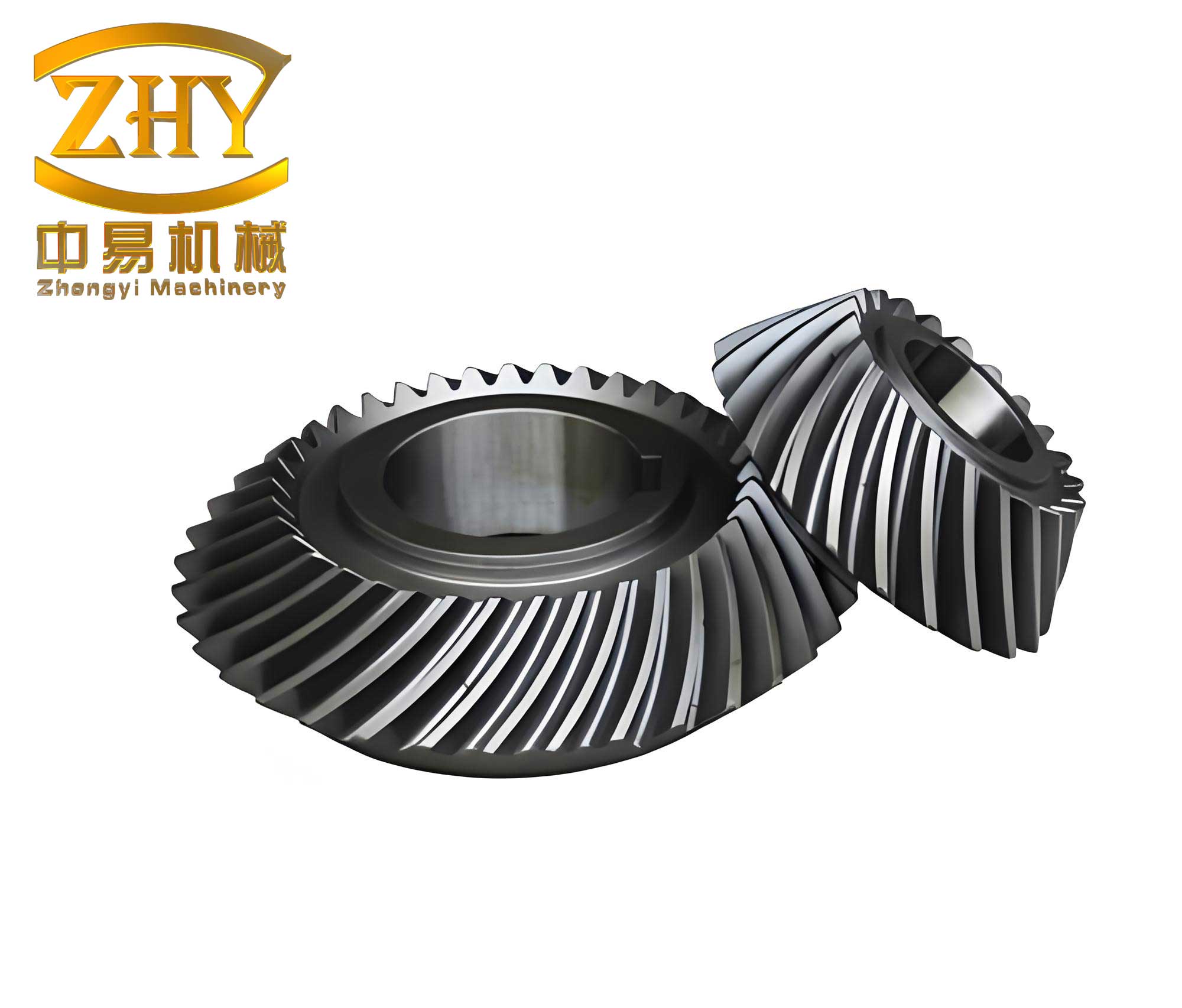
To begin my analysis, I developed a mathematical model to determine the optimal tooth tip clearance that minimizes power losses in a spiral gear pump. Power losses in such systems arise from three primary sources: leakage flow through the tooth tip clearance, elastic losses due to fluid compression, and viscous friction losses along the tooth tips. The classic leakage model for a spiral gear pump is given by:
$$Q_r = \frac{\Delta p \delta^3}{6\mu D} – \frac{1}{30}\pi n R_a \delta \frac{B}{\cos\beta} \times 60 \times 10^3$$
where \(Q_r\) is the leakage flow rate, \(\Delta p\) is the pressure difference between high and low-pressure zones, \(\mu\) is the dynamic viscosity, \(D\) is the total width of the tooth tips in the pressure-building region, \(n\) is the rotational speed, \(R_a\) is the tip circle radius, \(B\) is the face width, \(\delta\) is the tooth tip clearance, and \(\beta\) is the helix angle. However, this model does not account for mechanical deformations that occur under high operational loads. In a spiral gear pump, the gear shaft experiences radial deflection due to unbalanced forces, and the pump body deforms under hydraulic pressure and bearing reactions. These deformations effectively increase the tooth tip clearance, exacerbating leakage.
Considering shaft deflection, which I calculated to be 0.015 mm, the adjusted clearance becomes \(\delta_y = \delta + 0.015\). Incorporating this into the leakage model yields:
$$Q_r = \frac{\Delta p (\delta + 0.015)^3}{6\mu D} – \frac{1}{30}\pi n R_a (\delta + 0.015) \frac{B}{\cos\beta} \times 60 \times 10^3$$
Additionally, pump body deformation, which varies with angular position \(\theta\) relative to the ports, can be approximated as \(\delta_d = \delta + 0.00126\theta\). Integrating this over the pressure zone leads to a refined leakage expression. After combining both deformation effects, the comprehensive leakage model for the spiral gear pump is:
$$Q_r = \frac{\Delta p \delta (\delta^2 + 0.057\delta + 0.00103)}{6\mu D} – \frac{1}{30}\pi n R_a (\delta + 0.01896) \frac{B}{\cos\beta}$$
The power loss due to this leakage, \(\Delta N_{Q_r}\), is \(\Delta p \cdot Q_r\). Furthermore, the elastic loss from fluid compression is:
$$\Delta N_t = \frac{2\Delta p^2 V z}{E}$$
where \(V\) is the tooth space volume, \(z\) is the number of teeth, and \(E\) is the fluid bulk modulus. The viscous friction loss along the tooth tips is:
$$\Delta N_{\delta} = \frac{\pi n}{15} \left( \frac{\Delta p \delta}{2} D + \frac{\pi n \mu R_a}{30\delta} \right) \frac{B R_a}{\cos\beta}$$
The total power loss \(\Delta N_j\) is the sum of these components:
$$\Delta N_j = \Delta N_{Q_r} + \Delta N_t + \Delta N_{\delta}$$
By treating \(\delta\) as the variable and minimizing \(\Delta N_j\) with respect to \(\delta\), i.e., solving \(\frac{\partial \Delta N_j}{\partial \delta} = 0\), I derived the optimal tooth tip clearance. For the specific spiral gear pump parameters in this study, the optimal clearance was calculated to be approximately 0.0207 mm. This value represents a balance where the combined effects of leakage, compression, and friction are minimized, aiming to enhance the overall efficiency of the spiral gear system.
To validate this theoretical model, I conducted a series of numerical simulations using PumpLinx, a computational fluid dynamics (CFD) software specialized for pump analysis. The internal flow field of the double-circular-arc spiral gear pump was extracted and meshed, with particular attention to the tooth tip clearance regions. Three different clearance values were examined: 0.01 mm, 0.02 mm, and 0.03 mm. The mesh consisted of approximately 350,000 cells, with the rotor region discretized using a template mesher to accurately capture the dynamics of the spiral gears. Boundary conditions were set to simulate high-speed, high-pressure operation: an inlet pressure of 0.1 MPa, an outlet pressure of 25 MPa, and a rotational speed of 10,000 rpm. The turbulence model employed was the standard k-ε model, and cavitation was modeled using the full cavitation model to account for vapor formation and collapse. The working fluid was hydraulic oil with a density of 800 kg/m³ and a dynamic viscosity of 0.007 Pa·s.
The simulations revealed profound insights into how tooth tip clearance influences both cavitation and leakage in the spiral gear pump. Cavitation cloud plots at 50% face width cross-section showed distinct patterns for each clearance. At 0.01 mm, severe cavitation occurred across multiple regions, including the suction port, gear meshing zones, tooth backs, and tooth roots. At 0.02 mm, cavitation intensity diminished but remained present, while at 0.03 mm, cavitation was largely suppressed except in localized areas near the suction port. This trend indicates that larger clearances reduce cavitation by alleviating pressure drops, but at the cost of increased leakage. Pressure and velocity vector plots further illustrated that at smaller clearances (0.01 mm and 0.02 mm), high-pressure differences drove leakage through narrow gaps, whereas at 0.03 mm, a more established pressure gradient led to significant leakage flows from high to low-pressure chambers.
Quantitative data from the simulations are summarized in the tables below. Table 1 presents the outlet pressure pulsation rates for different tooth tip clearances, highlighting that pressure fluctuations decrease as clearance increases. Table 2 details the outlet flow pulsation rates, showing that while pulsation is minimized at 0.02 mm, the average flow rate peaks at this clearance before dropping at 0.03 mm due to heightened leakage.
| Tooth Tip Clearance (mm) | Maximum Pressure (MPa) | Minimum Pressure (MPa) | Average Pressure (MPa) | Pulsation Rate (%) |
|---|---|---|---|---|
| 0.01 | 25.88 | 24.50 | 25.10 | 5.48 |
| 0.02 | 25.41 | 24.77 | 25.10 | 2.55 |
| 0.03 | 25.17 | 24.97 | 25.10 | 0.78 |
| Tooth Tip Clearance (mm) | Maximum Flow (L/min) | Minimum Flow (L/min) | Average Flow (L/min) | Pulsation Rate (%) |
|---|---|---|---|---|
| 0.01 | 49.86 | 34.75 | 42.50 | 35.55 |
| 0.02 | 48.46 | 38.85 | 44.15 | 21.77 |
| 0.03 | 46.44 | 36.16 | 42.16 | 24.38 |
To further elucidate the interplay between clearance, cavitation, and leakage, I monitored specific points within the tooth tip gap regions. The data, plotted in Figure 1 (conceptual representation), demonstrates that as tooth tip clearance increases, the total gas volume fraction (indicative of cavitation) decreases, while fluid velocity (indicative of leakage) increases. This inverse relationship underscores a critical design trade-off: smaller clearances in spiral gear pumps can exploit cavitation for sealing benefits, but excessive cavitation degrades flow quality; larger clearances reduce cavitation but amplify leakage losses. The optimal point, as predicted by my model, lies where these competing effects are balanced, which for this spiral gear pump is near 0.02 mm.
The implications of these findings are significant for the design of spiral gear pumps. The spiral gear architecture inherently promotes smooth fluid transport, but the tooth tip clearance must be precisely controlled to harness its full potential. At 0.02 mm clearance, the spiral gear pump not only aligns with the theoretical optimum but also exhibits superior performance in terms of flow output stability. The pressure pulsation rate is a modest 2.55%, and the flow pulsation rate is minimized at 21.77%, with the highest average flow rate of 44.15 L/min. This confirms that the mathematical model accurately captures the complex dynamics involved, providing a reliable tool for optimizing spiral gear pump designs.
Moreover, the study reveals that cavitation at the tooth tip clearance can act as a dynamic seal. In smaller clearances, vapor bubbles formed during cavitation partially block the leakage path, reducing volumetric losses. However, this sealing effect diminishes as clearance increases, leading to direct fluid leakage. This phenomenon is particularly relevant for spiral gear pumps operating under transient conditions, where clearance variations may occur due to thermal expansion or wear. Designers must consider these factors to maintain performance over the pump’s lifecycle. For instance, in high-speed spiral gear applications, materials with low thermal expansion coefficients or active clearance compensation mechanisms could be employed to sustain the optimal gap.
In addition to the primary analysis, I explored secondary effects such as the impact of helix angle and tooth profile modifications on clearance optimization. The spiral gear’s helix angle, set at 31.3° in this case, influences the axial component of flow and leakage paths. A higher helix angle generally enhances flow continuity but may alter pressure distributions, affecting cavitation inception. Similarly, the double-circular-arc profile, with its gradual engagement, reduces pressure peaks compared to involute gears, which can mitigate cavitation severity. Future work could involve parametric studies on these variables to refine the optimal clearance model further.
From a practical standpoint, the results underscore the importance of manufacturing tolerances in spiral gear pump production. Achieving a tooth tip clearance of 0.02 mm requires precision machining and assembly techniques. Deviations, even by a few micrometers, can shift the pump away from its optimal operating point, leading to efficiency drops or increased cavitation damage. Therefore, quality control processes must be stringent, especially for spiral gear pumps destined for high-performance applications like aerospace or industrial hydraulics.
To conclude, this investigation into the effects of tooth tip clearance on leakage and cavitation characteristics in double-circular-arc spiral gear pumps has yielded both theoretical and practical insights. The developed mathematical model, which accounts for mechanical deformations and multiple power loss mechanisms, successfully predicted an optimal clearance of 0.0207 mm. Numerical simulations validated this finding, showing that at 0.02 mm clearance, the spiral gear pump achieves a harmonious balance: cavitation is controlled enough to prevent excessive flow disturbances, while leakage is minimized to maintain high volumetric efficiency. The spiral gear design proves adept at handling high-speed, high-pressure duties, but its performance is intricately linked to the management of tooth tip gaps. By optimizing this clearance, engineers can unlock the full potential of spiral gear pumps, ensuring reliable and efficient fluid power transmission in demanding environments. As spiral gear technology continues to evolve, these principles will guide advancements toward more robust and efficient pump systems.