
My research focuses on addressing the performance challenges encountered when traditional spiral gear pumps are pushed towards higher operational pressures and speeds, a necessary evolution for demanding applications in aerospace, aviation, and marine systems. The pursuit of miniaturization and enhanced performance in these hydraulic systems necessitates components that are not only smaller and lighter but also capable of reliable operation under extreme conditions. While spiral gear pumps offer inherent advantages like simplicity, robustness, and insensitivity to fluid contamination, their transition to high-pressure, high-speed regimes is hampered by significant issues. These include increased internal leakage leading to reduced volumetric efficiency, pronounced temperature rise, substantial pressure and flow pulsations contributing to noise and vibration, and severe radial loads on supporting bearings which accelerate wear and failure. This work, therefore, is dedicated to a comprehensive investigation—through theoretical modeling, advanced three-dimensional computational fluid dynamics (CFD) simulation, and experimental validation—of the dynamic fluid performance within a specialized circular arc spiral gear pump, aiming to diagnose root causes and propose effective improvements.
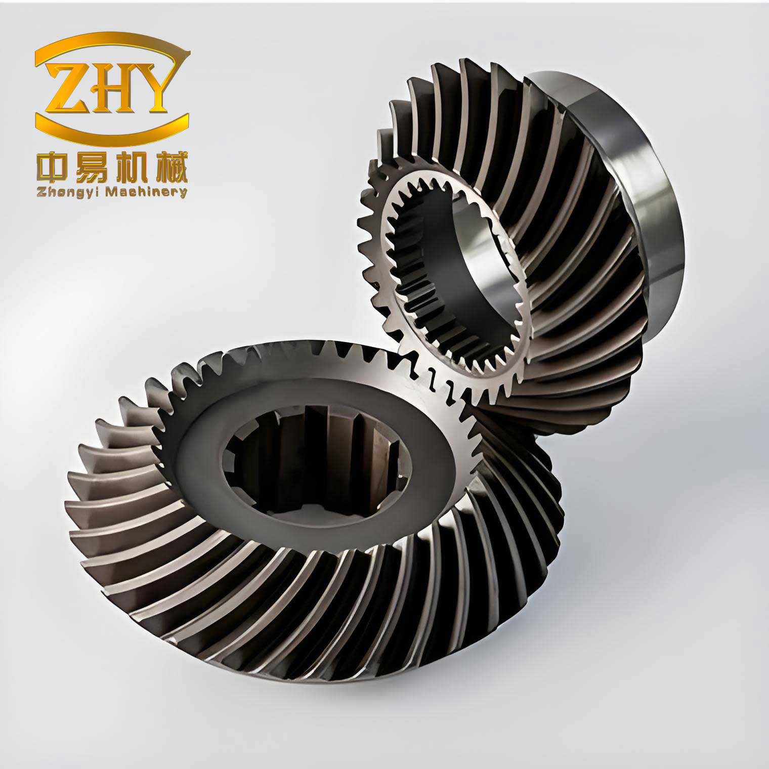
The core of the pump under investigation features a spiral gear pair with a unique circular arc tooth profile. This design is fundamentally different from conventional involute gears. The working principle ensures continuous single-tooth-pair contact along the spiral face, which theoretically eliminates the problematic trapped volume (or “困油”) phenomenon common in external gear pumps. This elimination directly addresses a major source of pressure spikes, flow ripple, and consequent noise. Furthermore, the symmetrical pressure distribution around the gear pair, a result of this specific meshing action, leads to a better balance of radial hydraulic forces compared to standard designs. This makes the circular arc spiral gear pump a promising candidate for high-pressure (targeting 25 MPa) and high-speed (targeting 10,000 rpm) operation in a compact package (with a gear pitch circle diameter of only 18 mm).
Theoretical Modeling of Flow Leakage
Leakage is the primary factor dictating the volumetric efficiency of a gear pump. In high-pressure systems, even minute clearances can lead to significant internal bypass flow. For an accurate prediction of performance, I developed a comprehensive analytical leakage model that accounts for multiple interrelated physical phenomena.
The total leakage flow \( Q_{leak} \) is considered as the sum of flows through several parallel paths:
$$ Q_{leak} = Q_{radial} + Q_{axial} + Q_{bearing} $$
Where \( Q_{radial} \) is the leakage through the clearance between the gear tip and the pump casing, \( Q_{axial} \) is the leakage across the gear side faces, and \( Q_{bearing} \) represents the radial flow through the clearance of the supporting sliding bearings.
1. Fundamental Radial and Axial Leakage
Assuming laminar flow in the small clearances, the pressure-driven (Poiseuille) and shear-driven (Couette) flows are superimposed. For the radial clearance, considering the gear rotation, the leakage per unit width can be derived from the simplified Navier-Stokes equation. For a spiral gear, the effective leakage path length is modified by the helix angle \( \beta \). The theoretical radial leakage \( Q_{radial,theo} \) is given by:
$$ Q_{radial,theo} = B \left( -\frac{\Delta P \delta_r^3}{6\mu D} + \frac{\pi n R_a \delta_r}{30 \cos\beta} \right) $$
where:
\( B \) = Gear width (m)
\( \Delta P \) = Pressure difference between outlet and inlet (Pa)
\( \delta_r \) = Nominal radial clearance (m)
\( \mu \) = Dynamic viscosity of the hydraulic oil (Pa·s)
\( D \) = Effective sealing width in the pressure transition zone (m)
\( n \) = Rotational speed (rpm)
\( R_a \) = Tip circle radius (m)
\( \beta \) = Helix angle
The axial leakage \( Q_{axial,theo} \) across the side plates, modeled as flow between two parallel disks with a central supply, is:
$$ Q_{axial,theo} = \frac{4 \Delta P (\theta_h + \theta_g) \delta_a^3}{3 \mu \ln(R_f / R_n)} $$
where:
\( \delta_a \) = Axial face clearance (m)
\( \theta_h, \theta_g \) = Angular spans of high-pressure and transition zones (rad)
\( R_f, R_n \) = Gear root radius and bearing inner radius (m), defining the flow annulus.
2. Influence of Temperature and Structural Deformation
The model is significantly refined by incorporating two critical real-world effects. First, the viscosity \( \mu \) of hydraulic oil is highly temperature-dependent. Using the Walther-ASTM equation, viscosity can be expressed as a function of temperature \( T \):
$$ \log_{10}[\log_{10}(\nu + a)] = b – c \log_{10}(T) $$
where \( \nu = \mu / \rho \) is the kinematic viscosity and \( a, b, c \) are oil-specific constants. This relationship shows that as temperature rises during operation, viscosity drops substantially, leading to increased leakage for a given pressure differential.
Second, under high pressure (e.g., 25 MPa), the pump casing deforms elastically. A static structural Finite Element Analysis (FEA) was performed, revealing that the deformation is not uniform. The radial clearance \( \delta_r \) becomes a function of angular position \( \theta \). An empirical fit from FEA results gave:
$$ \delta_r(\theta)_{deformed} = \delta_r + 0.00346 \cdot \theta $$
Integrating this variable clearance around the circumference yields a corrected radial leakage \( Q_{radial,def} \) that is greater than the theoretical value with a constant clearance.
3. Bearing Contribution and Complete Model
The sliding bearings themselves are a leakage path. For a journal bearing with eccentricity \( \epsilon \), the circumferential flow can be approximated as:
$$ Q_{bearing} \approx \pi n R_b B_b c (1 + \epsilon) $$
where \( R_b \) is the bearing radius, \( B_b \) its length, and \( c \) the radial clearance. The eccentricity \( \epsilon \) is determined by solving the Reynolds equation iteratively for the given load, which includes the net radial force on the gear shaft.
Combining all effects, the comprehensive leakage model becomes:
$$ Q_{leak} = f(\Delta P, n, \delta_r, \delta_a, \mu(T), \delta_r(\theta), \epsilon, \text{geometry}) $$
The following table summarizes the key geometric parameters of the pump used in the model and simulations:
| Geometric Parameter | Value |
|---|---|
| Number of Teeth | 7 |
| Module (mm) | 2 |
| Pitch Circle Diameter (mm) | 18.08 |
| Tip Circle Diameter (mm) | 21.334 |
| Gear Width (mm) | 10 |
| Helix Angle, \( \beta \) | 28° |
| Nominal Radial Clearance, \( \delta_r \) (mm) | 0.03 |
| Nominal Axial Clearance, \( \delta_a \) (mm) | 0.01 |
This model predicts that leakage increases non-linearly with both pressure and temperature, and that structural deformation can exacerbate leakage by over 10% under full load. The spiral gear‘s helix angle directly influences the effective clearance path, making its optimization crucial.
Three-Dimensional CFD Analysis of Internal Pump Flow
To dynamically analyze the complex, turbulent, and transient flow within the spiral gear pump, I employed ANSYS Fluent for three-dimensional CFD simulations. A full 3D model is essential for the spiral gear as it captures the axial flow components, the progressive meshing along the helix, and the true geometry of the clearance gaps, which are impossible to represent accurately in 2D.
Simulation Methodology
The fluid domain was extracted from the solid assembly of the casing and gears. A transient, pressure-based solver was used with the Realizable \( k-\epsilon \) turbulence model, which is well-suited for flows with strong rotation and strain. A critical aspect was managing the mesh deformation due to gear rotation. A dynamic mesh technique combining smoothing and local remeshing was applied to the fluid zones adjacent to the rotating gear surfaces. The boundaries were set as pressure-inlet (atmospheric) and pressure-outlet (specified load). The hydraulic oil was modeled as an incompressible fluid with density \( \rho = 850 \, \text{kg/m}^3 \) and a nominal dynamic viscosity.
Results on Flow Field Characteristics
The simulations successfully revealed the instantaneous pressure and velocity fields. The pressure distribution clearly showed compartments formed between the teeth and the casing, with pressure decreasing stepwise from the outlet to the inlet chamber. A significant finding was the maximum pressure at the meshing point near the outlet. For a condition of 25 MPa outlet pressure and 10,000 rpm, the peak meshing pressure reached approximately 28.7 MPa, which is only 1.15 times the outlet pressure. This relatively low pressure spike, compared to the multiples often seen in involute gear pumps, validates the circular arc spiral gear design’s effectiveness in mitigating violent pressure fluctuations and trapped volume effects.
The instantaneous flow rate at the outlet showed inherent pulsation. The simulation-derived average flow rate was compared against the theoretical flow (displacement × speed) minus the leakage calculated from the analytical model. The results showed close agreement, typically within 2-3%, which served as a strong cross-verification for both the CFD setup and the leakage model. The table below shows a comparison for different loads at 10,000 rpm:
| Outlet Pressure (MPa) | Theo. Flow (No Leak) L/min | Theo. Flow (With Leak Model) L/min | CFD Avg. Flow L/min |
|---|---|---|---|
| 5 | 20.02 | 19.60 | 19.38 |
| 15 | 20.02 | 19.25 | 19.01 |
| 25 | 20.02 | 18.92 | 18.80 |
Influence of Operating Conditions and Cavitation
Parametric studies were conducted by varying load and speed in the CFD model.
Effect of Load (Pressure): As the outlet pressure increased from 5 MPa to 25 MPa, the amplitude of pressure pulsation at the meshing point increased, but the ratio of peak pressure to outlet pressure actually decreased (from ~1.44 to ~1.15). The simulated average flow rate decreased with increasing load due to heightened leakage, confirming the trend from the theoretical model.
Effect of Speed: Increasing rotational speed from 4000 rpm to 12000 rpm at a constant 25 MPa load led to a higher amplitude of pressure pulsation. The flow rate increased linearly with speed, but the leakage, being a function of both pressure and speed, caused the volumetric efficiency to improve with speed—a trend also predicted by the leakage model where the shear-driven flow component becomes relatively more significant.
Cavitation Analysis: A multiphase mixture model with the Schnerr-Sauer cavitation model was activated to study vapor formation. Simulations showed that cavitation primarily occurred in the low-pressure region near the inlet, particularly as teeth disengaged. While the presence of vapor slightly altered the instantaneous flow pattern and increased the maximum meshing pressure by a small margin (~1 MPa), its overall impact on the time-averaged pump flow rate and major pressure trends under the studied high-pressure conditions was relatively minor. However, it remains a critical consideration for inlet design and noise generation.
The CFD analysis of the pump’s internal energy equation revealed that the temperature rise of the main working fluid was minimal (less than 1°C), indicating that the significant system temperature rise observed in preliminary tests must originate elsewhere, likely in the high-shear regions of the bearings.
Analysis and Optimization of the Hydrostatic Sliding Bearing
The sliding bearings in a high-pressure spiral gear pump are subjected to severe conditions: they must support large radial loads from the pressurized gears, operate at high surface speeds, and often suffer from inadequate cooling. Initial tests showed severe wear and high temperatures. To counteract the radial load, a hydrostatic pocket was machined into the bearing, fed directly from the pump’s high-pressure outlet. However, a pressure drop occurs between the supply and the pocket, limiting its load-balancing effectiveness. I used CFD to analyze this bearing’s internal flow and thermal field to understand and improve its performance.
Bearing Flow Field and Thermal Results
A 3D CFD model of the bearing’s oil film, including the inlet port, circumferential groove, hydrostatic pocket, and side clearances, was created. A laminar flow model was used due to the small clearances. Simulations at the design point (25 MPa supply, 10,000 rpm, eccentricity \( \epsilon = 0.6 \)) yielded critical insights. The pressure field showed the expected drop from the supply port to the hydrostatic pocket. The pocket pressure was found to be about 17.9 MPa, meaning a 7.1 MPa drop. This pressure could balance approximately 52% of the radial load on the shaft—significant but not complete. More importantly, the temperature field revealed a substantial temperature rise. The maximum oil temperature, located in the minimum film thickness region opposite the supply port, reached about 58°C above the inlet, with a mean temperature rise of 21°C. This confirmed that the bearings are a major heat source in the system.
Parametric Study for Bearing Improvement
To guide an optimization, I systematically varied key parameters:
1. Supply Pressure: Increasing pressure worsened the pressure drop across the pocket (reducing load support percentage) and increased the mean oil temperature rise due to higher shear stresses.
2. Rotational Speed: Higher speed had a negligible effect on pocket pressure but dramatically increased the oil temperature rise due to viscous shearing.
3. Eccentricity: Higher eccentricity \( \epsilon \) slightly reduced pocket pressure and drastically increased the maximum and mean oil temperatures, as the film thickness in the loaded zone became thinner.
To improve the design, I focused on two geometric parameters of the supply port:
1. Port Angle (\( \alpha \)): Varying the angular position of the inlet port relative to the load line. Results showed that the pocket pressure decreased slightly with increasing angle, but the mean temperature rise had a minimum at around \( \alpha = 47^\circ \).
2. Port Diameter (\( d \)): Increasing the port diameter significantly increased the pressure in the hydrostatic pocket, as more flow could enter with less restriction. It also generally decreased the mean oil temperature rise due to increased cooling flow, despite a potential increase in eccentricity. The trade-off was increased leakage flow from the bearing.
The following table summarizes the optimization trend for port diameter at 25 MPa, 10,000 rpm:
| Port Diameter, \( d \) (mm) | Pocket Pressure (MPa) | Radial Load Support* | Mean Temp. Rise (°C) |
|---|---|---|---|
| 1.2 | 8.9 | ~26% | 25.1 |
| 2.0 (Original) | 17.9 | ~52% | 21.0 |
| 2.4 (Optimized) | 19.5 | ~57% | 19.8 |
| 3.8 | 23.2 | ~67% | 18.6 |
*Estimated percentage of shaft radial load balanced by two bearings.
Based on a balance between improving load support, reducing temperature, and limiting excess leakage, an optimized bearing design was proposed with a supply port angle of \( 47^\circ \) and a diameter increased to 2.4 mm.
Experimental Validation
A dedicated test bench was constructed to validate the theoretical and simulation findings. The system incorporated a variable-speed drive, the prototype circular arc spiral gear pump, a proportional relief valve for load control, and sensors for pressure, flow, torque/speed, and temperature. Data was acquired via a PCI card and a LabVIEW interface. Experiments focused on temperature rise and flow rate performance.
Temperature Rise Tests
Tests compared pumps assembled with original bearings, optimized bearings (47°, 2.4mm port), and plain bearings without a hydrostatic pocket. Under an 8 MPa load at 2100 rpm, the results were clear: the optimized bearing reduced the pump casing temperature by approximately 3.1°C compared to the original design, and by about 9°C compared to the plain bearing after 600 seconds of operation. This confirmed the CFD-predicted thermal improvement. Furthermore, temperature rise increased with both increasing speed and increasing load, as predicted by the bearing simulations and the system’s thermal balance.
Flow Performance Tests
Flow rate was measured across a range of speeds under an 8 MPa load. The pump with optimized bearings consistently showed a higher flow rate (and thus higher volumetric efficiency) than the one with original bearings, especially at higher speeds. At 7500 rpm, the volumetric efficiency improved from about 60.2% to 64.4%. This demonstrated that the bearing optimization, by reducing friction and potentially associated distortions, also positively impacted the overall pump efficiency.
The measured flow rates were then plotted against the predictions from the comprehensive leakage model. The model’s predictions, which included the effects of temperature-derived viscosity and estimated bearing flow, followed the correct trend and were closer to experimental values than a simple no-leakage theory. The discrepancy at very high speeds highlighted areas for further model refinement, such as dynamic clearance changes due to thermal and pressure deformation. The experimental data conclusively showed that flow rate decreases with increasing load (due to increased leakage) and increases linearly with speed, validating the core trends from both the theoretical and CFD analyses.
Conclusion
This integrated study on the high-pressure, high-speed circular arc spiral gear pump has yielded significant insights and practical outcomes. The developed comprehensive leakage model, incorporating thermal-viscosity effects and casing deformation, provides a reliable tool for performance prediction. The three-dimensional CFD simulations unveiled the internal flow dynamics, confirming the spiral gear design’s superiority in minimizing pressure spikes and quantifying the effects of operating conditions. The analysis pinpointed the hydrostatic sliding bearing as a critical component for both system temperature and load capacity. Through focused CFD-driven optimization of the bearing’s supply port geometry, a design was achieved that simultaneously increases hydrostatic pressure for better load support and reduces operating temperature. Experimental tests on prototype pumps validated the trends from the models and conclusively demonstrated the performance gains from the bearing optimization, including reduced casing temperature and improved volumetric efficiency. This work establishes a framework for the analysis and enhancement of high-performance spiral gear pumps, contributing to their successful application in advanced, compact hydraulic systems.