
In mechanical transmission systems, spiral gears, also known as crossed helical gears, are utilized to transmit motion between non-parallel and non-intersecting shafts. These gears offer advantages such as simplicity in manufacturing, flexibility in achieving arbitrary shaft angles, insensitivity to errors in shaft angle and center distance, and ease of center distance adjustment. However, spiral gears operate under point contact conditions, which leads to higher contact stresses compared to parallel-axis gears, resulting in lower load-carrying capacity and a propensity for wear, especially in power transmission applications. This article delves into a detailed investigation of wear failures in spiral gears, focusing on material properties, heat treatment processes, finite element analysis, and corrective measures, with the aim of providing insights into enhancing the durability of spiral gears.
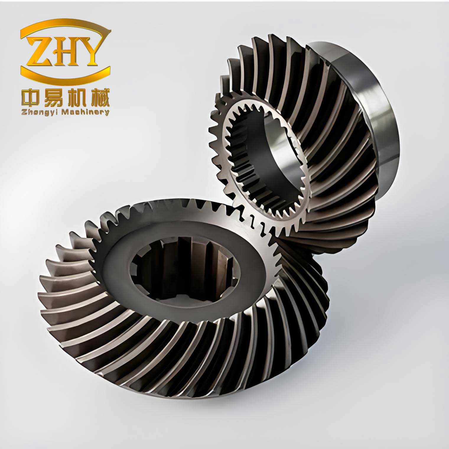
The specific spiral gear assembly under consideration consists of a driving gear and a driven gear, with the driving gear mounted on a reducer rotor and the driven gear connected via splines to a regulation system that supplies power oil and lubricant. During operational testing, severe wear was observed on the tooth surfaces of both spiral gears, prompting a thorough analysis. The initial design parameters included a driving gear with 23 teeth, a driven gear with 35 teeth, and a normal module of 2.0. The materials were 42CrMo for the driving gear, subjected to tempering, and ZCuSn10P1 for the driven gear, produced via sand casting. A reference or母型 design with identical geometric parameters had previously demonstrated satisfactory performance without significant wear, suggesting that the issue might stem from variations in material treatment rather than design flaws.
To understand the wear mechanisms in spiral gears, it is essential to review the fundamental contact mechanics. Spiral gears engage in point contact, where the contact stress can be approximated using Hertzian contact theory. The maximum contact pressure \( p_{\text{max}} \) for two curved surfaces in contact is given by:
$$ p_{\text{max}} = \frac{3F}{2\pi a b} $$
where \( F \) is the normal load, and \( a \) and \( b \) are the semi-major and semi-minor axes of the contact ellipse, respectively. For spiral gears, the contact ellipse dimensions depend on the gear geometry, including helix angles, shaft angle, and tooth profiles. The contact stress directly influences wear initiation, particularly when it exceeds the material’s fatigue limit. Wear in spiral gears can manifest as abrasive wear, adhesive wear, or surface fatigue, often exacerbated by inadequate lubrication or insufficient surface hardness.
The investigation into the wear failure of these spiral gears began with a comparative analysis of heat treatment processes. The reference spiral gears exhibited significantly higher surface hardness, which is a critical factor in wear resistance. The following table summarizes the heat treatment methods and hardness values for both the reference and the failed spiral gears:
| Component | Reference Design Heat Treatment | Reference Design Hardness | Failed Design Heat Treatment | Failed Design Hardness |
|---|---|---|---|---|
| Driving Spiral Gear | Surface hardening (e.g., carburizing and quenching) | >55 HRC | Tempering (调质) | ~280 HB |
| Driven Spiral Gear | Centrifugal casting | >110 HB | Sand casting | ~80 HB |
The disparity in hardness is striking. For metallic materials, the wear resistance is often correlated with hardness, as described by the Archard wear equation:
$$ V = K \frac{F_n L}{H} $$
where \( V \) is the wear volume, \( K \) is the wear coefficient, \( F_n \) is the normal load, \( L \) is the sliding distance, and \( H \) is the material hardness. Higher hardness \( H \) reduces wear volume \( V \), indicating that the lower hardness in the failed spiral gears likely contributed to accelerated wear. Additionally, the fatigue limit for contact stress \( \sigma_{H\lim} \) is material-dependent and increases with hardness. For the failed driving gear made of 42CrMo with tempering, \( \sigma_{H\lim} \) is approximately 199 MPa, while for the reference driving gear with surface hardening, \( \sigma_{H\lim} \) can reach 425 MPa or higher.
To quantify the contact stresses in the failed spiral gears, a finite element analysis (FEA) was conducted using ANSYS software. The FEA model included a segment of both spiral gears to capture the contact behavior accurately. The mesh was predominantly hexahedral, with refinement at the contact surfaces to ensure precision. Boundary conditions were applied as follows: the driving spiral gear was constrained cylindrically, allowing rotational freedom and subjected to a torque of 3.43 N·m derived from power calculations, while the driven spiral gear was fixed. The contact analysis considered two pairs of teeth in engagement, corresponding to a contact ratio of 1.83. The material properties were assigned based on the actual treatments: elastic modulus of 210 GPa for steel and 110 GPa for bronze, with Poisson’s ratios of 0.3 and 0.34, respectively.
The FEA results revealed that the contact stresses were concentrated in small regions near the tooth root and tip, consistent with point contact. The maximum von Mises stress reached approximately 335 MPa, as shown in the stress contour plot. This value exceeds the fatigue limit \( \sigma_{H\lim} = 199 \, \text{MPa} \) for the tempered driving gear, indicating that the spiral gears were operating under conditions prone to surface fatigue and wear. The contact pressure distribution can be further analyzed using the Hertzian formula adapted for spiral gears:
$$ a = \sqrt[3]{\frac{3F R_e}{2E’}} , \quad b = \sqrt[3]{\frac{3F R_e}{2E’} \left( \frac{1}{\kappa} \right)} $$
where \( R_e \) is the equivalent radius of curvature, \( E’ \) is the equivalent elastic modulus, and \( \kappa \) is the ellipticity parameter. For spiral gears, the curvature radii vary along the tooth profile, complicating the stress calculation. The FEA provides a more accurate assessment by considering the actual geometry and load distribution.
The wear in spiral gears is not solely a function of contact stress but also involves sliding velocities and lubrication conditions. The sliding velocity \( v_s \) in spiral gear mesh can be expressed as:
$$ v_s = v_1 – v_2 $$
where \( v_1 \) and \( v_2 \) are the tangential velocities of the driving and driven spiral gears at the contact point. This sliding action generates frictional heat and promotes wear if the lubricant film is insufficient. The specific film thickness \( \lambda \), defined as the ratio of lubricant film thickness to composite surface roughness, should ideally be greater than 3 for elastohydrodynamic lubrication (EHL). For the failed spiral gears, the lower hardness may have increased surface roughness, reducing \( \lambda \) and leading to boundary lubrication, thereby accelerating wear.
Based on the analysis, corrective measures were implemented to enhance the wear resistance of the spiral gears. The driving spiral gear material was changed to 20CrMnTi, a carburizing steel, and subjected to carburizing and quenching to achieve a high surface hardness. Carburizing involves diffusing carbon into the surface layer at high temperatures, followed by quenching to form a hard martensitic case while retaining a tough core. The case depth and hardness profile are critical; typically, a case depth of 0.5–1.0 mm and a surface hardness of 58–62 HRC are targeted. The driven spiral gear, made of ZCuSn10P1 tin bronze, was produced using centrifugal casting instead of sand casting. Centrifugal casting improves material density, reduces porosity, and enhances mechanical properties, including hardness and fatigue strength. The expected hardness after centrifugal casting is above 110 HB, comparable to the reference design.
To validate these improvements, a 500-hour endurance test was conducted under operational conditions, including frequent high-low speed transitions. The driving spiral gear speed alternated between 1930 rpm and 2900 rpm within seconds, simulating harsh operational cycles. After the test, the spiral gears were disassembled and inspected. The following table presents the tooth thickness measurements before and after the test, indicating no significant wear:
| Measurement Point | Driving Spiral Gear Tooth Thickness (mm) | Driven Spiral Gear Tooth Thickness (mm) |
|---|---|---|
| After Initial Run-in | 2.68 | 2.62 |
| After 300 Hours | 2.68 | 2.62 |
| After 400 Hours | 2.68 | 2.62 |
| After 500 Hours | 2.68 | 2.62 |
Visual inspection confirmed that the tooth surfaces of both spiral gears remained smooth with only minor polishing marks, contrasting sharply with the severe wear observed previously. This demonstrates that the enhanced heat treatment and casting methods effectively mitigated wear in the spiral gears. The success can be attributed to the increased surface hardness, which raised the fatigue limit above the operational contact stresses, and the improved material integrity from centrifugal casting, which reduced susceptibility to surface damage.
Further theoretical considerations support these findings. The contact fatigue life of spiral gears can be estimated using the Lundberg-Palmgren model, which relates fatigue life to stress and material parameters. The basic equation for rolling contact fatigue life is:
$$ L_{10} = \left( \frac{C}{P} \right)^p $$
where \( L_{10} \) is the life at 10% failure probability, \( C \) is the dynamic load capacity, \( P \) is the equivalent load, and \( p \) is an exponent (typically 3 for point contact). By increasing the surface hardness through carburizing, the dynamic load capacity \( C \) is enhanced, thereby extending the fatigue life of the spiral gears. Additionally, the residual compressive stresses induced by carburizing and quenching further inhibit crack propagation, improving resistance to surface fatigue.
In terms of material science, the microstructure of the carburized spiral gear surface consists of fine martensite with retained austenite, which provides high hardness and toughness. The core microstructure of 20CrMnTi remains ductile, absorbing impact loads. For the bronze driven spiral gear, centrifugal casting yields a finer grain structure and fewer defects compared to sand casting, as quantified by the following relation for yield strength:
$$ \sigma_y = \sigma_0 + k d^{-1/2} $$
where \( \sigma_0 \) and \( k \) are constants, and \( d \) is the grain diameter. Finer grains (smaller \( d \)) increase yield strength \( \sigma_y \), contributing to better wear resistance. The combination of these material enhancements ensures that the spiral gears can withstand the point contact stresses without premature wear.
Moreover, the lubrication regime for spiral gears should be optimized to complement the material improvements. Using high-viscosity oils or additives that form protective films can further reduce wear. The film thickness \( h \) in EHL for spiral gears can be calculated using the Dowson-Higginson equation:
$$ h = 2.65 \frac{R_e^{0.43} (\eta_0 v)^{0.7} \alpha^{0.54}}{E’^{0.03} F^{0.13}} $$
where \( \eta_0 \) is the dynamic viscosity, \( v \) is the rolling velocity, and \( \alpha \) is the pressure-viscosity coefficient. Ensuring adequate film thickness minimizes metal-to-metal contact, thereby protecting the hardened surfaces of the spiral gears.
In conclusion, the wear failure in the spiral gears was primarily due to insufficient surface hardness resulting from suboptimal heat treatment and casting processes. Through comprehensive analysis involving heat treatment checks and finite element simulations, it was determined that the contact stresses exceeded the material’s fatigue limits. The implementation of carburizing and quenching for the driving spiral gear and centrifugal casting for the driven spiral gear successfully elevated the surface properties, as confirmed by a 500-hour operational test. This case underscores the importance of material selection and processing in the design of durable spiral gears for power transmission applications. Future work could explore advanced coatings or surface treatments to further extend the life of spiral gears under extreme conditions.
The study also highlights the need for standardized testing protocols for spiral gears, including accelerated wear tests and condition monitoring techniques such as vibration analysis or oil debris analysis. By integrating these approaches, the reliability of spiral gears in critical systems can be enhanced, ensuring efficient and long-lasting performance. Ultimately, the insights gained from this analysis contribute to the broader field of gear engineering, emphasizing that even minor changes in material processing can have significant impacts on the wear behavior of spiral gears.