
In the processing of soybean meal, a key by-product of soybean oil extraction with high plant protein content, extrusion technology plays a crucial role in enhancing nutritional value and suitability as animal feed. Traditional three-screw extruders are known for their efficiency, multifunctionality, and precise temperature control, but they often exhibit inadequate mixing and shearing performance, leading to lower extrusion quality. To address this limitation, we propose a novel variable-speed three-screw extruder design incorporating a bevel gear transmission system and kneading block elements. This design aims to improve dispersion and mixing capabilities by introducing coaxial speed variation and enhanced shear regions. In this article, we present a comprehensive analysis of the three-dimensional flow field within this innovative extruder, utilizing optimization algorithms, computational fluid dynamics (CFD) simulations, and experimental validation.
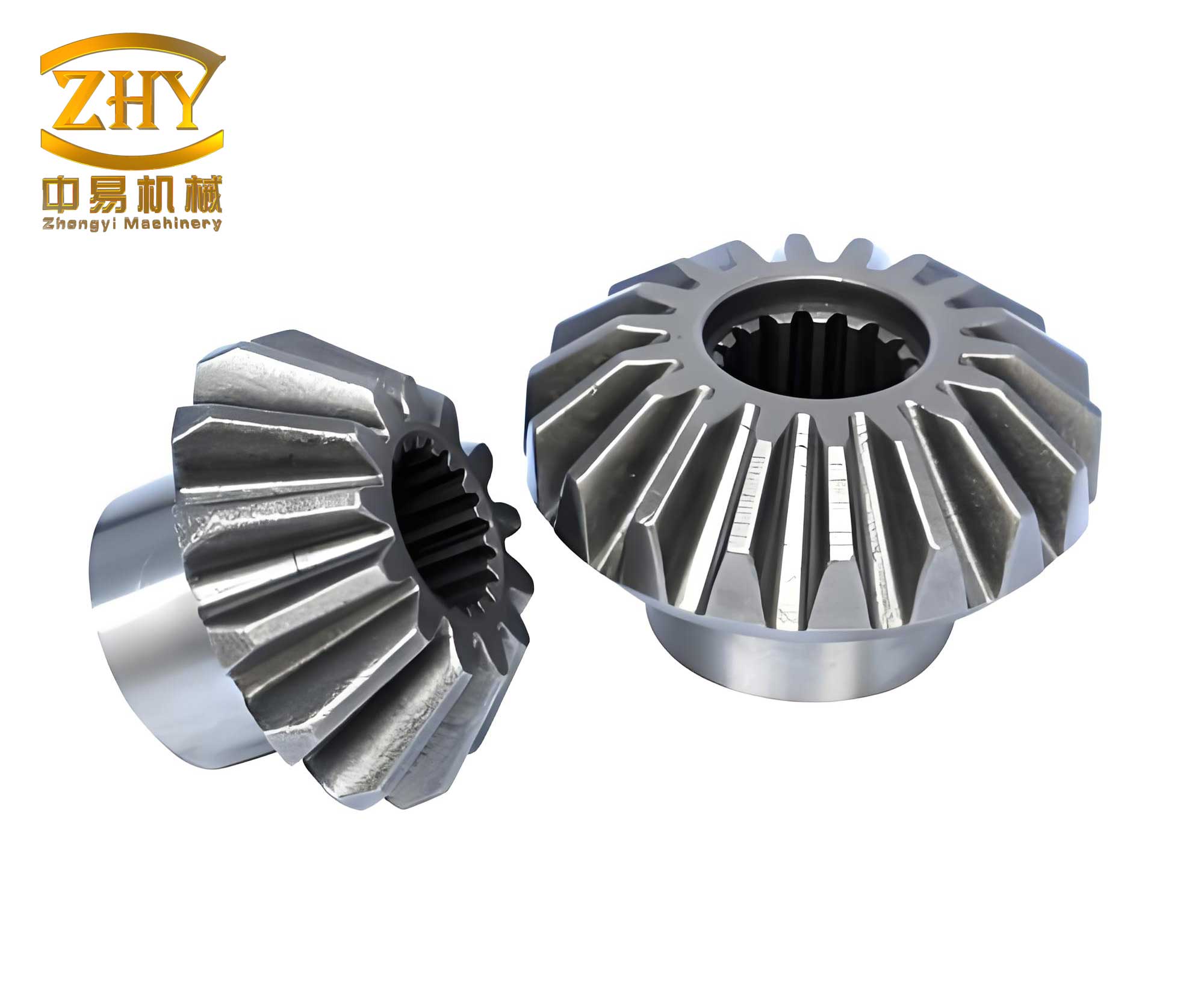
The core innovation lies in the integration of a bevel gear mechanism within the screw structure, enabling speed reduction and reversal in specific sections. Bevel gears are chosen for their compact size, lightweight, and efficient power transmission in confined spaces, making them ideal for embedding in screw shafts. This allows for variable-speed operation along the same axis, disrupting material flow and prolonging residence time. Additionally, neutral kneading blocks are strategically placed to further shear and blend the material. We employ MATLAB’s particle swarm optimization (PSO) algorithm to determine optimal screw geometry parameters, such as channel depth and pitch, maximizing throughput while maintaining mixing performance. The three-dimensional model is constructed in SolidWorks, and flow simulations are conducted using ANSYS CFX based on finite element methods. We compare the pressure field, velocity field, and velocity streamlines with those of a conventional three-screw extruder to quantify improvements. Experimental tests on a TRI-80 extruder validate the simulation findings, confirming that the variable-speed design significantly enhances mixing uniformity and shear performance.
The design process begins with optimizing screw parameters to balance throughput and mixing. The volumetric flow rate \( Q \) for a screw extruder is expressed as:
$$ Q = \rho A v $$
where \( \rho \) is material density, \( A \) is cross-sectional area, and \( v \) is axial velocity. For a screw with outer diameter \( D \), inner diameter \( d \), channel depth \( H \), pitch \( S \), and screw speed \( n \), the area and velocity can be derived as:
$$ A = \frac{\pi}{4} (D^2 – d^2) – \frac{\delta H}{\sin \alpha} $$
$$ v = \frac{S n}{60} $$
with spiral angle \( \alpha = \arctan\left(\frac{S}{\pi D}\right) \). Combining these, the flow rate becomes:
$$ Q = k \left[ \frac{\pi}{4} \left( D^2 – (D – H)^2 \right) – \frac{\delta H}{\sin \left( \arctan \frac{S}{\pi D} \right)} \right] S $$
where \( k \) is a constant dependent on material and operating conditions. Using PSO, we optimize \( H \) and \( S \) within practical ranges (1–8 mm for depth, 5–25 mm for pitch). The algorithm iteratively searches for parameters maximizing \( Q \), resulting in optimal values of \( H = 7.4 \, \text{mm} \) and \( S = 19.6 \, \text{mm} \). The optimization process is summarized in Table 1, highlighting key iterations and fitness values.
| Iteration | Channel Depth (mm) | Pitch (mm) | Fitness (Q) |
|---|---|---|---|
| 50 | 7.2 | 18.9 | -4.58 |
| 100 | 7.5 | 19.5 | -4.62 |
| 150 | 7.4 | 19.6 | -4.64 |
| 200 | 7.4 | 19.6 | -4.64 |
The screw design features three segments: a conventional conveying segment (100 mm), a mixing segment with kneading blocks (50 mm), and a variable-speed conveying segment (50 mm) housing the bevel gear system. The bevel gear assembly consists of two driving gears with 17 teeth each and a driven gear with 34 teeth, achieving a speed reduction ratio of 2. This configuration reduces screw speed from 120 rpm in conventional segments to 60 rpm in the variable-speed segment, while also reversing rotation direction. The kneading blocks are arranged with a 60° staggered angle to promote shear and reorientation. Figure below illustrates the compact bevel gear mechanism integrated into the screw shaft.
For flow simulation, we model soybean meal as an incompressible non-Newtonian power-law fluid in laminar flow, ignoring inertia and body forces. The governing equations include continuity, motion, and constitutive equations. The continuity equation is:
$$ \frac{\partial v_x}{\partial x} + \frac{\partial v_y}{\partial y} + \frac{\partial v_z}{\partial z} = 0 $$
The motion equations are:
$$ \frac{\partial p}{\partial x} = \frac{\partial \tau_{xx}}{\partial x} + \frac{\partial \tau_{yx}}{\partial y} + \frac{\partial \tau_{zx}}{\partial z} $$
$$ \frac{\partial p}{\partial y} = \frac{\partial \tau_{xy}}{\partial x} + \frac{\partial \tau_{yy}}{\partial y} + \frac{\partial \tau_{zy}}{\partial z} $$
$$ \frac{\partial p}{\partial z} = \frac{\partial \tau_{xz}}{\partial x} + \frac{\partial \tau_{yz}}{\partial y} + \frac{\partial \tau_{zz}}{\partial z} $$
The power-law constitutive equation is:
$$ \tau = \mu \dot{\gamma}^n $$
where \( \tau \) is shear stress, \( \mu \) is consistency coefficient, \( \dot{\gamma} \) is shear rate, and \( n \) is power-law index. Material properties for soybean meal are density \( \rho = 665 \, \text{kg/m}^3 \), viscosity \( \mu = 1930 \, \text{Pa} \cdot \text{s}^n \), with \( n = 0.5 \) assumed, and barrel temperature set at 140°C. Boundary conditions are defined in Table 2.
| Boundary | Condition | Value |
|---|---|---|
| Inlet | Velocity | 0.05 m/s |
| Outlet | Pressure | 3 MPa |
| Conventional Screw Speed | Rotational | 120 rpm |
| Variable-Speed Screw Segment | Rotational (via bevel gear) | 60 rpm (reversed) |
| Barrel Wall | No-slip | 0 m/s |
The flow domain is meshed with tetrahedral elements (537,671 elements, 137,627 nodes) using a 3 mm element size. Simulations compare the variable-speed three-screw extruder against a traditional three-screw extruder with uniform speed. Results for pressure field, velocity field, and streamlines are analyzed quantitatively.
Pressure field analysis reveals distinct differences. In the traditional extruder, pressure increases steadily along the flow direction, indicating consistent pumping but limited mixing. In the variable-speed design, pressure rises initially, then plateaus in the kneading block region due to lack of pumping action, drops in the variable-speed segment because of reverse rotation from the bevel gear, and rises again in the final conveying segment. This fluctuating pressure profile, summarized in Table 3 for key axial positions, demonstrates reduced overall pressure build-up but enhanced mixing through flow disruption.
| Axial Position (m) | Traditional Screw Pressure (MPa) | Variable-Screw Pressure (MPa) |
|---|---|---|
| 0.05 | 1.2 | 1.1 |
| 0.10 (Kneading Block) | 2.5 | 2.0 |
| 0.15 (Variable-Speed Segment) | 3.8 | 1.5 |
| 0.20 | 4.5 | 2.8 |
| 0.25 | 5.0 | 4.0 |
Velocity field analysis shows that the variable-speed segment, driven by the bevel gear system, reduces axial velocity from 0.12 m/s to -0.06 m/s, causing reflux and turbulence. Velocity vectors indicate clockwise rotation in variable-speed sections versus counterclockwise in conventional sections, confirming directional change. Streamlines in the traditional extruder are smooth and continuous, whereas in the variable-speed design, they are fragmented and twisted in mixing and variable-speed regions, indicating repeated splitting and recombination of material. The axial velocity profile along a monitoring line is depicted in Figure 11, with data points extracted for comparison. The mathematical representation of axial velocity \( v_z \) as a function of axial distance \( x \) can be approximated by piecewise equations:
$$ v_z(x) =
\begin{cases}
0.12 \, \text{m/s} & \text{for } 0 \leq x < 0.01 \, \text{m} \\
0.00 \, \text{m/s} & \text{for } 0.01 \leq x < 0.015 \, \text{m} \\
-0.06 \, \text{m/s} & \text{for } 0.015 \leq x < 0.02 \, \text{m} \\
0.12 \, \text{m/s} & \text{for } 0.02 \leq x \leq 0.03 \, \text{m}
\end{cases} $$
This highlights how the bevel gear-induced speed reduction and reversal decelerate flow, extending residence time.
To validate simulations, experimental tests are conducted on a TRI-80 three-screw extruder with soybean meal at a feed rate of 5 kg/h and barrel temperature of 140°C. Extrusion times are measured for both traditional and variable-speed screws at various speeds, as shown in Table 4. The variable-speed design increases residence time by 21–30%, corroborating improved mixing from prolonged material exposure to shear.
| Screw Speed (rpm) | Traditional Screw Extrusion Time (s) | Variable-Speed Screw Extrusion Time (s) | Increase in Residence Time (%) |
|---|---|---|---|
| 80 | 45.5 | 54.5 | 19.8 |
| 100 | 35.7 | 44.6 | 24.9 |
| 120 | 30.9 | 39.7 | 28.5 |
| 140 | 22.4 | 29.1 | 29.9 |
| 160 | 17.7 | 21.2 | 19.8 |
The bevel gear transmission is pivotal in achieving these results. By enabling coaxial speed variation, it introduces a reverse-thread effect that hinders forward transport and creates backflow. This, combined with kneading blocks, amplifies shear rates and mixing efficiency. The power consumption of the bevel gear system can be estimated using torque transmission equations. For a bevel gear set with gear ratio \( i = 2 \), the output torque \( T_{\text{out}} \) relates to input torque \( T_{\text{in}} \) as:
$$ T_{\text{out}} = i \cdot T_{\text{in}} \cdot \eta $$
where \( \eta \) is efficiency (typically 0.95–0.98 for bevel gears). In our design, this allows the variable-speed segment to operate at higher torque for shearing, albeit at lower speed.
In conclusion, the novel variable-speed three-screw extruder, incorporating a bevel gear mechanism and optimized geometry, demonstrates superior mixing and shearing performance compared to traditional designs. The bevel gear system facilitates speed reduction and direction reversal, disrupting flow patterns and extending residence time by up to 30%. Future work could explore different bevel gear configurations, such as spiral bevel gears for smoother transmission, or multi-stage speed variations. Additionally, optimizing the placement of kneading blocks relative to bevel gear segments may further enhance performance. This research provides a framework for designing advanced extruders with tailored mixing capabilities, leveraging the versatility of bevel gear transmissions in food and feed processing applications.