
Traditional gear transmissions, such as cylindrical and conical gears, operate with a single degree of freedom (DOF). They are designed to transmit rotational motion between axes with fixed relative positions. While effective for countless applications, this fundamental characteristic limits their use in emerging fields that demand more adaptable and reconfigurable motion transmission, such as robotics, biomimetic joints, and vector propulsion systems. The need for mechanisms capable of transmitting rotation between axes whose angle can vary dynamically has driven the development of multi-degree-of-freedom gears, often referred to as spherical gears.
Existing spherical gear designs, like the involute annular gear, offer two rotational degrees of freedom but are primarily suited for transmitting motion about the polar axis of a sphere. They are not inherently designed for efficient power transmission between intersecting axes at arbitrary, variable angles. Conversely, another promising design is the semi-spherical bevel gear (SBG) pair. This configuration also possesses two rotational degrees of freedom but is specifically conceived to enable rotational transmission between intersecting shafts where the shaft angle itself can be varied. This capability avoids the mechanical complexity, large size, and inertia associated with using combinations of conventional bevel gears and universal joints to achieve similar functionality. The SBG finds potential application in compact robot wrists, biomimetic articulation, and other advanced mechanical systems requiring versatile motion.
Previous research on the SBG has focused primarily on its structural concept without a deep investigation into its meshing theory or the mathematical definition of its tooth surfaces. Building upon the tooth surface generation principles of other spherical gears, this work proposes a comprehensive design methodology for the SBG based on the theory of two-parameter envelope. We derive the complete mathematical model of its tooth surface, analyze its meshing characteristics, and evaluate its mechanical performance through finite element analysis, thereby enriching the theory and application of multi-DOF gear transmissions.
Meshing Principle of the Semi-Spherical Bevel Gear Pair
The meshing transmission between a pair of SBGs can be conceptually understood as the pure rolling of two pitch spheres. As illustrated in the following analysis, an SBG pair is designed to transmit rotation between two shafts intersecting at an arbitrary angle $\vartheta$, where $0 < \vartheta < \pi$. For any fixed instantaneous value of the shaft angle $\vartheta$, the meshing of the gears is kinematically equivalent to the meshing of two infinitesimally thin conical bevel gears. The latitude circle on the pitch sphere at the contact point serves as the pitch circle of these instantaneous equivalent bevel gears. When $\vartheta$ approaches zero, the shafts become parallel, and the transmission equivalently resembles that of spur cylindrical gears. When $\vartheta$ approaches $\pi$, the shafts become collinear, the radius of the contact latitude approaches zero, and no effective tooth meshing occurs.
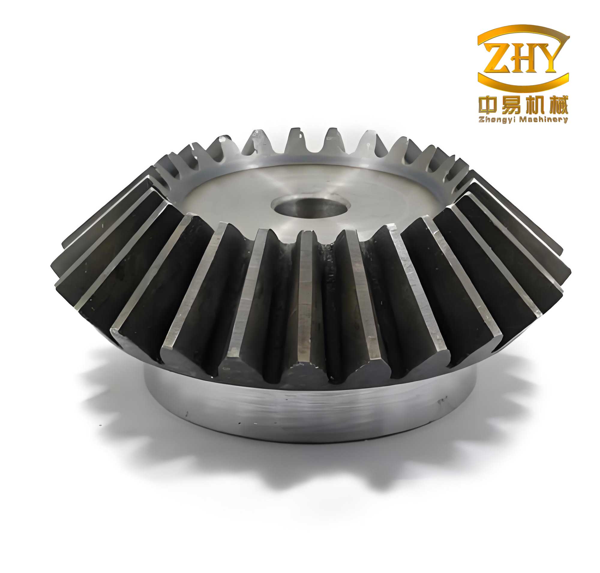
Considering that the tooth surface of a conventional bevel gear can be generated by the envelope of a crown gear (or generating gear), the tooth surface of the SBG can be generated through the conjugate motion between a crown gear and the SBG blank, where the motion involves two independent parameters. The crown gear’s pitch plane is tangent to the pitch sphere, with its center at the intersection of the rotation axis and the pitch plane. For any given shaft angle, the meshing between the SBG and the crown gear is analogous to that between a crown gear and an infinitesimally thin bevel gear.
Since the meshing of an SBG pair at a fixed shaft angle is equivalent to a pair of thin bevel gears, the transverse tooth profile of the SBG is identical to that of a bevel gear. Therefore, the equivalent gear for an SBG pair at any angle $\vartheta$ is a standard bevel gear. The meshing occurs in the transverse plane defined by the instantaneous contact latitude. Consequently, the fundamental condition for correct meshing is that at every possible shaft angle $\vartheta$, the transverse module $m_t$ and the transverse pressure angle $\alpha_t$ of both gears must be equal:
$$ m_{t1}(\vartheta_1) = m_{t2}(\vartheta_2), \quad \alpha_{t1} = \alpha_{t2} $$
where $\vartheta_1$ and $\vartheta_2$ are the instantaneous pitch cone angles of the SBGs’ transverse profiles, satisfying $\vartheta_1 + \vartheta_2 = \vartheta$. The contact ratio at any shaft angle is the same as that of its equivalent bevel gear pair.
Tooth Surface Equation of the Crown Gear
The crown gear is a special case of a bevel gear with a pitch cone angle of $\pi/2$, making its pitch surface a flat plane. We employ this crown gear as the generating tool (similar to a rack in cylindrical gear generation) to envelop the working tooth surface of the SBG through conjugate motion. The crown gear tooth surface equation is derived using coordinate transformation methods. We define coordinate system $S_3(x_3, y_3, z_3)$ fixed to the crown gear, with its origin at the center of the pitch plane. The $z_3$-axis is perpendicular to this plane. The tooth is symmetric about the plane $y_3O_3z_3$, with the $y_1$ and $y_2$ axes passing through the pitch point and lying on the tooth flank surfaces.
In an auxiliary coordinate system $S_0(x_0, y_0, z_0)$, a point $\mathbf{p}$ on the crown gear surface can be represented as $[0, \rho, 0]^T$, where $\rho$ is the radial distance. The transformation from $S_0$ to $S_3$ is given by the matrix $\mathbf{L}_{30}$:
$$
\mathbf{L}_{30} = \mathbf{L}_{32}(\theta) \cdot \mathbf{L}_{21}(\alpha_s) \cdot \mathbf{L}_{10}(\varphi) =
\begin{bmatrix}
\cos \theta & \sin \theta & 0 \\
-\sin \theta & \cos \theta & 0 \\
0 & 0 & 1
\end{bmatrix}
\cdot
\begin{bmatrix}
\cos \alpha_s & -\sin \alpha_s \sin \varphi & \sin \alpha_s \cos \varphi \\
0 & \cos \varphi & \sin \varphi \\
-\sin \alpha_s & -\cos \alpha_s \sin \varphi & \cos \alpha_s \cos \varphi
\end{bmatrix}
$$
Here, $\theta = \theta_p / 2$, with $\theta_p$ being the angular tooth thickness on the pitch circle, $\alpha_s$ is the standard pressure angle, and $\varphi$ is a surface parameter. The position vector of point $\mathbf{p}$ in $S_3$, $\mathbf{r}^{(p)}$, is therefore:
$$
\mathbf{r}^{(p)} = \mathbf{L}_{30} \cdot \mathbf{r}^{(p)}_0 = \rho
\begin{bmatrix}
\cos\varphi\sin\theta – \cos\theta\sin\alpha_s\sin\varphi \\
\cos\theta\cos\varphi + \sin\theta\sin\alpha_s\sin\varphi \\
-\cos\alpha_s\sin\varphi
\end{bmatrix}
$$
This equation defines the crown gear’s tooth surface, which will serve as the generating surface.
Tooth Surface Equation of the Semi-Spherical Bevel Gear
The conjugate motion model between the crown gear and the SBG blank is established. The crown gear tooth surface acts as the generating tool to envelope the SBG tooth surface. The $z_{1t}$-axis, perpendicular to the crown gear’s pitch plane, initially coincides with the SBG’s $z_{20}$-axis. The crown gear translates with velocity $V_{10}$ and rotates clockwise about $z_{1t}$ by angle $\phi_1$ with angular velocity $\boldsymbol{\omega}^{(1)}$. Concurrently, the SBG blank undergoes two rotations: a swing about the $x_{20}$-axis by angle $\beta$ with angular velocity $\boldsymbol{\omega}^{(3)}$, and a rotation about its own axis $z_{2t}$ by angle $i \cdot \phi_1$ with angular velocity $\boldsymbol{\omega}^{(2)}$, where $i$ is the desired speed ratio.
To describe this complex motion, several coordinate systems are defined: a fixed system $S_{20}$, systems $S_{1t}$ and $S_{2t}$ attached to the moving components, and intermediate systems $S_1$ and $S_2$. The transformation matrices between these systems are crucial. The matrix from the crown gear system $S_1$ (after rotation $\phi_1$) to the fixed system $S_{20}$ is $\mathbf{M}_{201}$:
$$
\mathbf{M}_{201} =
\begin{bmatrix}
\cos\phi_1 & -\sin\phi_1 & 0 & 0 \\
-\sin\phi_1 & -\cos\phi_1 & 0 & r\tan\beta \\
0 & 0 & -1 & r \\
0 & 0 & 0 & 1
\end{bmatrix}
$$
The matrix from the SBG system $S_2$ (after rotations $\beta$ and $i\phi_1$) to $S_{20}$ is $\mathbf{M}_{220}$:
$$
\mathbf{M}_{220} =
\begin{bmatrix}
\cos(i\phi_1) & -\cos\beta\sin(i\phi_1) & \sin\beta\sin(i\phi_1) & 0 \\
\sin(i\phi_1) & \cos\beta\cos(i\phi_1) & -\cos(i\phi_1)\sin\beta & 0 \\
0 & \sin\beta & \cos\beta & 0 \\
0 & 0 & 0 & 1
\end{bmatrix}
$$
Here, $r$ is the radius of the pitch sphere common to all SBGs. Based on the two-parameter envelope theory, the meshing equations are derived using the condition that the relative velocity at the contact point between the two surfaces must be orthogonal to the common normal vector. This relative velocity depends on both motion parameters, $\phi_1$ and $\beta$. For a fixed $\beta$, the relative velocity $\mathbf{v}^{(12, \phi_1)}$ is calculated from the angular velocities $\boldsymbol{\omega}^{(1)} = -\dot{\phi}_1 \mathbf{k}_{20}$ and $\boldsymbol{\omega}^{(2)} = -i\dot{\phi}_1 \sin\beta \mathbf{j}_{20} – i\dot{\phi}_1 \cos\beta \mathbf{k}_{20}$, and the translational velocity $\mathbf{v}_{10} = d(r\tan\beta)/dt \, \mathbf{j}_{20}$. For a fixed $\phi_1$, the relative velocity $\mathbf{v}^{(12, \beta)}$ involves $\boldsymbol{\omega}^{(3)} = -\dot{\beta} \mathbf{i}_{20}$.
The meshing equations are then given by $f(\rho, \varphi, \beta) = \mathbf{N}_{20} \cdot \mathbf{v}^{(12, \beta)} = 0$ and $g(\rho, \varphi, \phi_1) = \mathbf{N}_{20} \cdot \mathbf{v}^{(12, \phi_1)} = 0$, where $\mathbf{N}_{20}$ is the normal vector of the crown gear surface expressed in $S_{20}$, derived as $\mathbf{N}_{20} = \mathbf{M}_{201} (\partial \mathbf{r}^{(p)} / \partial \rho \times \partial \mathbf{r}^{(p)} / \partial \varphi)$. Solving these equations yields:
$$
\begin{aligned}
f &= \cos\alpha_s \left( r – \sec^2 \beta \right) \sin\theta – \rho \cos\theta \cos\varphi – \rho \sin\theta \sin\varphi + r \sin\alpha_s \tan\beta \\
g &= \cos\alpha_s \left( -1 + i \cos\beta \right) \cos\varphi + i \sin\beta \left[ -\cos(\theta + \phi_1) \sin\varphi + \cos\varphi \sin(\theta + \phi_1) \right]
\end{aligned}
$$
Finally, the tooth surface equation of the SBG in its own coordinate system $S_2$ is a system of equations:
$$
\begin{cases}
\mathbf{r}_2(\rho, \varphi, \beta, \phi_1) = \mathbf{M}_{220}^{-1} \cdot \mathbf{M}_{201} \cdot \mathbf{r}^{(p)} \\
f(\rho, \varphi, \beta) = 0 \\
g(\rho, \varphi, \phi_1) = 0
\end{cases}
$$
This set defines the semi-spherical bevel gear tooth surface as a function of the generating parameters $\rho, \varphi$ and the motion parameters $\beta, \phi_1$, linked by the two meshing conditions $f=0$ and $g=0$. The generation process implies complex machine tool kinematics requiring two independent CNC axes for $\phi_1$ and $\beta$, making multi-axis CNC machining a practical necessity for manufacturing these gears.
Geometric Modeling and Finite Element Analysis
The size and extent of the SBG tooth surface enveloped by the crown gear depend on the crown gear’s tooth number and the pitch sphere radius. For this study, a crown gear with 12 teeth and a speed ratio $i=1$ was selected. The standard pressure angle was set to $20^\circ$ and the pitch sphere radius $r$ to 21 mm. Based on the derived tooth surface equations, a computational simulation was performed using Matlab to calculate discrete coordinate points defining the complete tooth flank. An example of the computed tooth profile is shown conceptually below.
The coordinate data was exported and formatted for use in CAD software (e.g., Pro/ENGINEER). Through operations like importing curve data, creating boundary-blended surfaces for left and right flanks, and solidifying these surfaces, a three-dimensional solid model of the SBG pair was constructed. This model accurately represents the complex geometry derived from the meshing theory.
The three-dimensional SBG pair model was imported into ANSYS Workbench for transient structural analysis. The material was assigned properties typical of alloy steel: Young’s modulus $E = 2 \times 10^5$ MPa and Poisson’s ratio $\mu = 0.3$. To balance computational accuracy and efficiency, a localized mesh refinement strategy was employed. The teeth and contact regions were meshed finely, while non-critical regions had a coarser mesh. The contact between the gear teeth was defined as frictional, with a coefficient set to 0.1. Boundary conditions were applied to simulate power transmission: a constant torque of $M = 100$ N·m was applied to the driver gear, while a constant rotational speed of 2 rad/s was applied to the driven gear. Analyses were conducted for various intersecting shaft angles $\vartheta$.
The finite element analysis confirms that the SBG pair operates under point contact conditions. The simulated stress distributions for shaft angles of $20^\circ$ and $60^\circ$ are shown conceptually, revealing the location and magnitude of maximum stresses. The key results for maximum tooth root bending stress and maximum contact stress across different shaft angles are summarized in the following table.
| Intersecting Shaft Angle, $\vartheta$ (°) | Max. Bending Stress (MPa) | Max. Contact Stress (MPa) |
|---|---|---|
| 20 | 201.22 | 605.66 |
| 60 | 305.39 | 916.15 |
| 100 | 412.37 | 986.42 |
| 140 | 546.67 | 1054.98 |
| 160 | 912.45 | 20590.00 |
The analysis of the simulation results indicates clear trends. As the intersecting shaft angle $\vartheta$ increases, both the maximum contact stress and the maximum tooth root bending stress show a significant increase. This is attributed to two primary factors: first, the instantaneous point of contact moves closer to the tooth tip as the angle increases, which is generally a region of higher stress concentration; second, the effective transverse module of the equivalent bevel gear decreases with increasing $\vartheta$, leading to thinner tooth geometry and reduced load-carrying capacity at the root. A critical observation is the dramatic, non-linear increase in stresses, particularly the contact stress, as $\vartheta$ approaches $180^\circ$. At these extreme angles, the tooth thickness at the potential contact zone becomes exceedingly small, leading to a severe stress concentration and potentially plastic deformation or failure, indicating a practical operational limit for the SBG pair well below this theoretical maximum.
Conclusion
This work presents a thorough investigation into the design and analysis of a semi-spherical bevel gear with two degrees of freedom. Based on the principle of two-parameter envelope meshing theory, we established a conjugate motion model between a crown gear and the SBG blank. From this model, the complete mathematical formulation for the SBG tooth surface was rigorously derived. The correctness of the derived equations was validated by generating coordinate data via simulation and successfully constructing a three-dimensional solid model using CAD software. This process confirms the feasibility of the proposed design method.
A finite element analysis was conducted to evaluate the mechanical performance of the SBG pair under load. The results demonstrate that the gear pair operates under point contact conditions. Furthermore, a clear relationship between the intersecting shaft angle and gear stress was established: both the maximum contact stress and the maximum tooth root bending stress increase as the shaft angle $\vartheta$ increases. This increase is primarily due to the migration of the contact point toward the tooth tip and the reduction in the effective transverse tooth dimensions. Notably, a stress singularity is observed as $\vartheta$ approaches $180^\circ$, defining a practical upper limit for the useful range of this type of multi-degree-of-freedom bevel gear transmission. This study provides a foundational theoretical and numerical framework for the design and application of semi-spherical bevel gears in advanced mechanical systems requiring variable-axis power transmission.