
The extraction of power from the high-pressure rotor in modern aeroengines is typically accomplished through a central drive spiral bevel gear system. The operational speeds of these gear systems often exceed the first critical speed of the rotor, leading to significant vibration challenges during the transition through critical regions. Excessive vibration not only impacts the operational smoothness and noise but also poses severe risks to the structural integrity and reliability of the engine. My research focuses on a passive vibration control strategy employing a squeeze film damper (SFD), combined with an elastic squirrel cage support, to mitigate these vibrations. This article details the theoretical modeling, dynamic characteristic analysis, and experimental validation of the SFD’s effectiveness within a spiral bevel gear system.
The core of the problem lies in the dynamic interaction between the flexible rotor and the meshing action of the bevel gears. While active methods like tooth profile modification exist, they increase cost and complexity. The integration of an SFD offers a robust solution by introducing damping to dissipate vibrational energy. The squirrel cage lowers the effective support stiffness, providing frequency tuning to avoid resonance. To accurately predict and analyze the system’s behavior, I developed a comprehensive nonlinear dynamic model that couples the gear mesh excitations with the nonlinear oil film forces of the SFD.
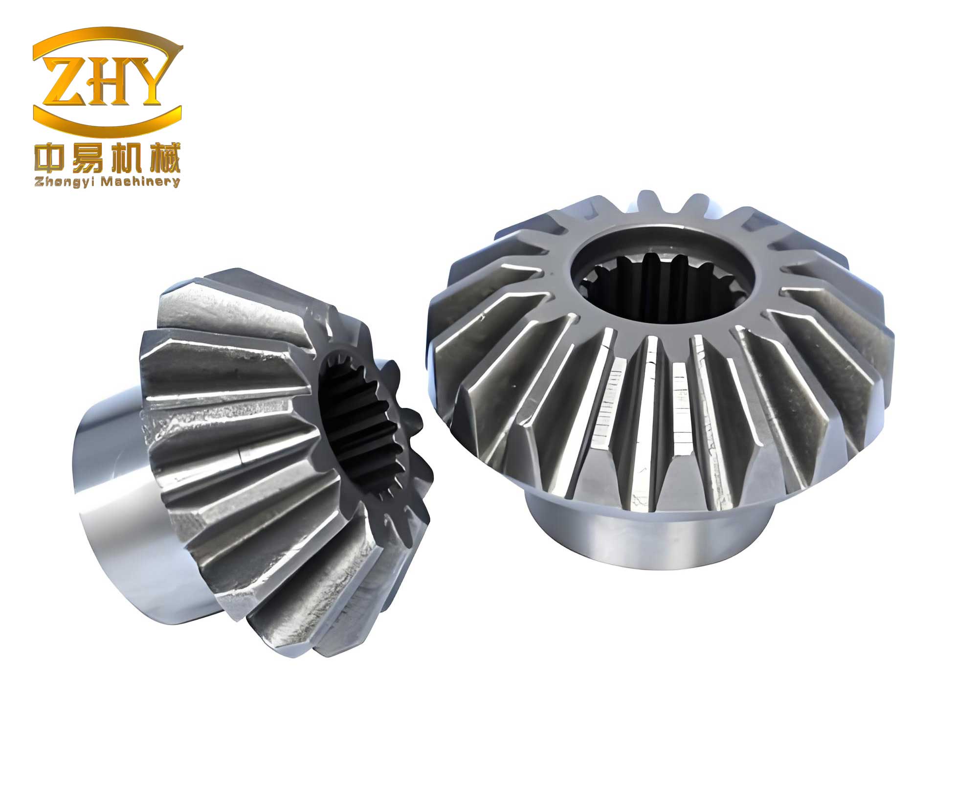
The foundation of the model is the finite element discretization of the flexible gear shafts using Timoshenko beam elements. This approach allows for the accurate representation of shaft flexibility, gyroscopic effects, and distributed mass and inertia. The pinion and gear are integrated into this shaft model. For the driven gear shaft with a thin, curved web, a combination of a flexible shaft modeled with beam elements and a rigid disk representing the gear’s mass and gyroscopic properties was used. The system’s governing equation of motion is derived using the Lagrangian formulation:
$$
\mathbf{M}\ddot{\mathbf{x}} + (\mathbf{C} + \Omega \mathbf{G})\dot{\mathbf{x}} + \mathbf{Kx} = \mathbf{F}
$$
Here, $\mathbf{M}$, $\mathbf{C}$, $\mathbf{K}$, and $\mathbf{G}$ are the global mass, damping, stiffness, and gyroscopic matrices assembled from the shaft and support elements. $\Omega$ is the rotational speed, $\mathbf{x}$ is the vector of nodal displacements, and $\mathbf{F}$ is the global force vector encompassing external torque, gear mesh forces, and SFD oil film forces.
The primary internal excitation in the system originates from the meshing of the bevel gears. This is characterized by two key factors: the static transmission error (STE) and the time-varying mesh stiffness (TVMS). The STE, a function of manufacturing imperfections, was obtained by measuring the actual tooth surfaces using a coordinate measuring machine and reconstructing the meshing condition through an unloaded tooth contact analysis algorithm. The TVMS was calculated via detailed finite element contact analysis using ABAQUS software. The dynamic mesh force $F_m$ along the line of action is given by:
$$
F_m = k_m(t) f(\delta_r) + c_m \dot{\delta}_r
$$
$$
\delta_r = \mathbf{h}\mathbf{x} – e_s(t)
$$
where $k_m(t)$ is the TVMS, $c_m$ is the mesh damping, $e_s(t)$ is the STE, $\mathbf{h}$ is a transformation vector projecting nodal displacements to the mesh direction, and $f(\delta_r)$ is a backlash function.
The nonlinear forces generated by the SFD are central to the vibration control. The SFD in this configuration consists of a journal (the outer race of the bearing and the elastic support cage) rotating concentrically within a stationary housing with a thin oil film in between. The pressure distribution within this oil film is governed by the Reynolds equation for a short bearing approximation under dynamic conditions:
$$
\frac{\partial}{R^2 \partial \theta} \left( h^3 \frac{\partial p}{\partial \theta} \right) + \frac{\partial}{\partial z} \left( h^3 \frac{\partial p}{\partial z} \right) = \frac{6\mu}{R} \left( \dot{x} \sin(\theta + \beta) – \dot{y} \cos(\theta + \beta) \right) \frac{\partial h}{\partial \theta} + 12\mu \left( \dot{x} \cos(\theta + \beta) + \dot{y} \sin(\theta + \beta) \right)
$$
where $p$ is the oil film pressure, $h = c(1 + \epsilon \cos \theta)$ is the film thickness, $c$ is the radial clearance, $\epsilon$ is the eccentricity ratio, $\mu$ is the fluid viscosity, $R$ is the journal radius, and $\beta$ is the attitude angle. The journal center velocities are $\dot{x}$ and $\dot{y}$. Rather than using approximate closed-form solutions, I employed a finite element method to solve this equation on a discretized mesh of the oil film, enabling real-time computation of the nonlinear oil film forces $F_x$ and $F_y$ as functions of journal displacement and velocity. These forces were then incorporated into the global force vector $\mathbf{F}$ at the corresponding node of the bevel gear system model.
The parameters of the studied spiral bevel gear pair are summarized in the table below:
| Parameter | Pinion (Driven) | Gear (Driver) |
|---|---|---|
| Number of Teeth | 47 | 55 |
| Module | 3 | |
| Shaft Angle | 90° | |
| Spiral Angle | 35° | |
| Face Width (mm) | 19 | |
| Pitch Diameter (mm) | 141.0 | 165.0 |
The dynamic response of the bevel gear system was analyzed under both rigid support and SFD support conditions. A critical comparison was made at the bearing location near the SFD installation. At a high-speed operational condition of 13,400 rpm, the vibration acceleration spectra revealed dominant frequency components. These included low-frequency components related to shaft rotation (e.g., 3.5 times the shaft frequency) and high-frequency components at the gear mesh frequency ($f_m$) and its higher harmonics (2$f_m$, 3$f_m$, 4$f_m$), surrounded by sidebands due to modulation with shaft frequencies.
The effectiveness of the SFD was pronounced. The following table contrasts key vibration amplitudes under both support conditions at 13,400 rpm:
| Frequency Component | Rigid Support Amplitude | SFD Support Amplitude | Reduction |
|---|---|---|---|
| Low-Frequency (3.5x Shaft Freq) | ~38 g | ~9.8 g | ~74% |
| 1st Mesh Frequency ($f_m$) | ~20 g | ~19.7 g | Minor |
The results clearly demonstrate that the SFD is exceptionally effective in suppressing low-frequency vibrations, which are directly related to the rotor’s unbalance and critical speed response. The damping mechanism effectively dissipates the energy associated with the shaft’s orbital motion. The reduction in the 3.5-order vibration from 38g to 9.8g is particularly significant. The impact on the high-frequency mesh components was less dramatic, as these are primarily forced vibrations generated by the inherent geometric excitations of the bevel gears themselves.
To validate the theoretical model and findings, a dedicated test rig was constructed. The rig replicated the aeroengine central drive configuration, featuring the spiral bevel gear pair with an SFD and squirrel cage support on the driving gear shaft. Vibration acceleration was measured on the housing near the SFD during speed sweeps and at constant high speeds. A comparison between the theoretical predictions and experimental measurements at 13,400 rpm showed strong agreement in the spectral composition. The amplitudes of the first six mesh frequency harmonics were of the same order of magnitude. The maximum amplitude occurred at the first mesh frequency, with the theoretical value at 19.7 g and the experimental measurement at 16.9 g, confirming the model’s predictive capability.
The waterfall plot from a speed ramp from 9,200 to 14,700 rpm further validated the model. Both theoretical and experimental results identified vibration peaks near 10,200 rpm and 11,600 rpm, with comparable amplitude levels. This correlation confirms that the coupled nonlinear model—integrating flexible bevel gear shafts, time-varying mesh properties, and finite-element-based SFD forces—accurately captures the essential dynamics of the system.
In conclusion, the integration of a squeeze film damper into a high-speed spiral bevel gear transmission system presents a highly effective solution for vibration attenuation. The primary mechanism is the suppression of low-frequency, rotor-dynamic vibration modes, which are critical when operating through or near critical speeds. The nonlinear dynamics of the bevel gear system, driven by static transmission error and time-varying mesh stiffness, were successfully modeled and coupled with the nonlinear damping of the SFD. The theoretical analysis, focused on the complex interactions within the bevel gear rotor system, yielded results that were consistent with experimental observations. This work underscores the importance of considering coupled gear-mesh and rotor-dynamic phenomena when designing dampers for advanced mechanical transmissions like those found in aeroengines, and it provides a validated modeling framework for optimizing the vibration performance of bevel gear systems.