
The operational environment for gear shafts in coal mining machinery is exceptionally demanding, characterized by cyclic and shock loading. This necessitates that the component possesses outstanding comprehensive mechanical properties, including high strength, good toughness, and significant fatigue resistance. Traditionally, such gear shafts were manufactured as monolithic forgings, followed by localized induction hardening of the gear teeth. This approach, however, presented several limitations: a propensity for cracking in the hardened tooth regions and flanks, and significant challenges in adapting to batch production of multiple specifications due to the constraints of forging large, intricate single pieces. To overcome these hurdles, an alternative manufacturing strategy was adopted: constructing the gear shaft as a welded assembly, where a high-strength gear ring is joined to a tough shaft, followed by a full-section quench and temper heat treatment. This shift introduces two critical technical challenges that must be meticulously controlled: the tendency for cracking in the weld and heat-affected zone (HAZ) during heat treatment, and the control of distortion in the final component.
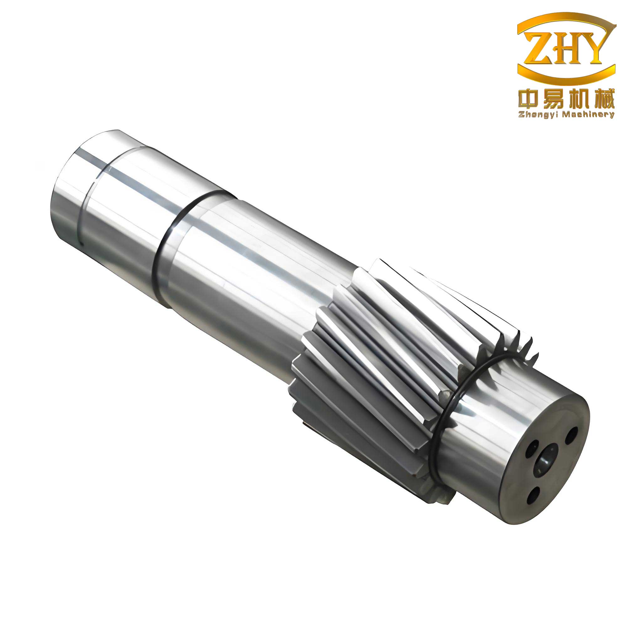
The core of the problem lies in the union of two different medium-carbon, quenched and tempered steels. In this specific application, the gear ring material is 34CrNiMo, while the shaft is made from 42CrMo. The final assembly is required to achieve a uniform hardness in the range of 350-380 HBW. The inherent material differences in this composite welded gear shaft create complexities during the austenitizing and quenching cycle.
Analysis of Cracking and Distortion Mechanisms
The primary drivers of failure during the heat treatment of a dissimilar-material welded gear shaft are thermally and transformation-induced stresses.
Thermal Stress ($\sigma_{th}$)
During heating and cooling, a temperature gradient ($\nabla T$) exists between the surface and the core of the component, and more critically, between the different material zones of the gear shaft. This gradient arises due to differences in thermal conductivity ($k$) and results in differential thermal expansion/contraction, generating thermal stress. For a simple case, the thermal stress can be approximated by:
$$\sigma_{th} \approx E \cdot \alpha \cdot \Delta T$$
where $E$ is Young’s modulus, $\alpha$ is the coefficient of thermal expansion, and $\Delta T$ is the temperature difference. When the gear shaft combines materials with differing $\alpha$ and $k$ values, the stress state at the weld interface becomes more complex and pronounced, elevating cracking risk.
Transformation Stress ($\sigma_{tr}$)
This is perhaps the more significant factor. During quenching, the martensitic transformation, which is a diffusionless shear transformation accompanied by a volume increase, does not occur simultaneously throughout the component. The transformation start temperature ($M_s$) and the kinetics depend heavily on chemical composition. 34CrNiMo and 42CrMo have different hardenabilities and $M_s$ points. This inhomogeneity means that as one section of the welded gear shaft transforms to martensite and expands, adjacent sections may still be austenitic or in another phase, creating immense internal (organizational) stresses. The superposition of $\sigma_{th}$ and $\sigma_{tr}$ can easily exceed the local fracture strength of the material, particularly in the HAZ, which may have undergone unfavorable microstructural changes during welding.
Distortion Drivers
Distortion in the final welded gear shaft is the macroscopic manifestation of these internal stresses. The factors exacerbating distortion include:
- Material Disparity: As with cracking, different phase transformation behaviors and expansion coefficients lead to uneven dimensional changes.
- Geometric Asymmetry: The cross-sectional area of the gear ring is vastly different from that of the shaft, leading to non-uniform cooling rates.
- Mass Effect: The overhanging gear teeth are susceptible to sagging or bending under their own weight at elevated temperatures during austenitizing.
- High-Temperature Tempering: Achieving the desired toughness requires a high tempering temperature (e.g., 500°C+). The stress relief and microstructural changes during this stage introduce additional, albeit more predictable, dimensional shifts.
The manufacturing sequence demands that gear teeth are finish-ground post-heat-treatment. Therefore, the total heat treatment distortion must be contained within the final grinding allowance, typically set at 0.4 mm for the tooth profile.
Developed Heat Treatment Strategy for the Welded Gear Shaft
A comprehensive, multi-stage heat treatment protocol was developed to mitigate these risks, ensuring the integrity and precision of the final welded gear shaft.
Stage 1: Pre-Weld Heat Treatment of Individual Components
Prior to welding, both the 34CrNiMo gear ring blank and the 42CrMo shaft undergo an independent quench and temper (quench & temper) process. The objective is not to achieve the final hardness, but to establish a uniform, fine-grained microstructure of tempered martensite or lower bainite with a hardness range of 230-270 HBW. This serves critical purposes:
- Microstructural Homogenization: Eliminates segregations and creates a consistent starting structure, improving weldability.
- Grain Refinement: A fine prior-austenite grain size enhances toughness and reduces the propensity for grain growth during subsequent welding and heat treatment cycles.
- Reduced Final Distortion: By starting from a stress-relieved, stable condition, the dimensional changes during the final post-weld quench & temper are less severe compared to starting from an as-forged or normalized state.
The process parameters are summarized below:
| Component | Material | Austenitizing | Quenching Medium | Tempering | Target Hardness |
|---|---|---|---|---|---|
| Gear Ring Blank | 34CrNiMo | 860-870°C | Oil | 580-620°C | 230-270 HBW |
| Shaft | 42CrMo | 840-850°C | Oil | 560-600°C | 230-270 HBW |
Stage 2: Welding and Post-Weld Stress Relief
Following machining of weld preparations, the components are welded using a carefully selected filler metal. To further enhance the integrity of the dissimilar steel joint, a buttering or transition layer of a low-carbon steel weld metal can be deposited on the bevel faces prior to final welding. This creates a more gradual compositional gradient. Immediately after welding, the entire gear shaft assembly undergoes a stress-relief anneal. This is conducted in a pit-type furnace, typically at 600-650°C for several hours, followed by slow cooling. This step serves to:
- Drastically reduce residual welding stresses.
- Temper any hard, brittle martensite formed in the HAZ during welding.
- Prepare a more uniform stress state for the final quenching operation, minimizing the risk of quench cracking.
Stage 3: Final Quench and Temper (Full Hardening)
This is the most critical step to achieve the final properties in the welded gear shaft. A detailed procedure was established to control heating, cooling, and support.
| Process Step | Key Parameters & Rationale |
|---|---|
| 1. Fixturing & Loading | The gear shaft is mounted vertically in a custom support fixture/stand. This aligns the axis of the shaft vertically, minimizing sagging distortion of the gear teeth under gravity at high temperature. Loading is done in a pit-type furnace for uniform heating. |
| 2. Austenitizing | Employs a “fast heating” strategy. The furnace is pre-heated to 900°C before charging the part. The part is then held at a final austenitizing temperature of 860°C. This minimizes total time at high temperature, reducing oxidation, decarburization, and grain growth. Soaking time is calculated based on the thickest section. |
| 3. Quenching | The gear shaft is removed from the furnace and quenched vertically (along its axis, the direction of least resistance) into a well-agitated oil bath. Vigorous agitation ensures uniform and rapid heat extraction initially. A critical control is to reduce or stop agitation once the component’s core temperature passes below the $M_s$ point of the materials. This slows cooling through the martensitic transformation range, thereby reducing the rate of martensite formation and the associated transformational stresses ($\sigma_{tr}$). |
| 4. Tempering | Performed immediately after quenching to avoid delayed cracking. A high temperature of 500°C is used to achieve the desired hardness range (350-380 HBW) and, more importantly, to transform the as-quenched martensite into tough, tempered martensite (tempered martensite) and to relieve the majority of the quenched-in stresses. Tempering time is substantial, often 4-6 hours minimum. |
Experimental Validation and Performance Data
To validate the proposed process and quantify the benefits of post-weld heat treatment versus the as-welded condition, a series of test blocks simulating the welded joint were produced and subjected to different thermal cycles. The microstructures and mechanical properties were then analyzed.
Microstructural Analysis
The microstructures observed in the weld and HAZ under different conditions are summarized below. The superiority of the full quench & temper process is evident.
| Sample Condition | Weld Metal Microstructure | HAZ Microstructure | Implication |
|---|---|---|---|
| As-Welded (Air Cooled) | Bainite (B) + Martensite (M, traces) | Bainite (B) + Ferrite (F) + Martensite (M, localized) | Inhomogeneous mix. Upper bainite and localized high-carbon martensite are detrimental to toughness and promote crack initiation. |
| Full Quench & Temper (860°C Oil Quench + 500°C Tempering) | Uniform Tempered Martensite/Sorbitic | Uniform Tempered Martensite/Sorbitic | Homogeneous, fine structure providing optimal strength-toughness balance. Eliminates HAZ brittleness. |
| Full Quench & Temper with Low-Carbon Buttering Layer | Tempered Martensite/Sorbitic + Fine Ferrite-Pearlite | Tempered Martensite/Sorbitic + Fine Ferrite-Pearlite | Even more refined gradient structure. The buttering layer provides a cushion, improving overall joint toughness. |
Mechanical Property Testing
Tensile, hardness, and impact tests were conducted across the weld joint. The data conclusively demonstrates the necessity of the full heat treatment cycle for the welded gear shaft.
| Sample Condition | Tensile Strength (MPa) | Elongation (%) | Impact Toughness (J) | Fracture Location | Hardness Range |
|---|---|---|---|---|---|
| As-Welded (Air Cooled) | 969 | 7.8 | 33.4 | HAZ | ~50 HRC (Max) to 256 HV (Min) |
| Full Quench & Temper (Standard) | 1179 | 4.5 | 17.1 | Weld Metal | 258 – 308 HV |
| Full Quench & Temper (with Buttering) | 1067 | 6.6 | 60.2 | Weld Metal | 247 – 383 HV |
The results are striking:
- As-Welded State: Shows the lowest strength and highly variable hardness, with a very brittle zone (50 HRC) leading to failure in the HAZ. Impact toughness is moderate but unreliable.
- Standard Full Treatment: Significantly increases tensile strength. However, impact toughness is somewhat lower, and fracture occurs in the weld, indicating it is now the “weakest” link, but in a more predictable manner.
- Treatment with Buttering: Offers the best compromise. While tensile strength is slightly lower than the standard treatment, it exhibits a remarkable combination of good strength, excellent ductility (highest elongation), and superior impact toughness (60.2 J). The hardness gradient is also smoother. This confirms that the buttering layer strategy is highly effective for optimizing the performance of a welded gear shaft.
Production Validation on Actual Gear Shafts
Implementing the finalized process—including pre-weld heat treatment, buttering, post-weld stress relief, and the controlled final quench & temper—on production gear shafts yielded consistently excellent results. All components met the stringent distortion and hardness specifications.
| Inspection Parameter | Technical Requirement | Measured Results (Range) | Assessment |
|---|---|---|---|
| Gear Ring Radial Runout | < 0.40 mm | 0.30 – 0.40 mm | Within spec, allows for finish grinding. |
| Gear Ring Face Runout | < 2.0 mm | 1.0 – 1.1 mm | Well within specification. |
| Shaft Straightness (Runout) | < 2.5 mm | 1.5 – 1.8 mm | Well within specification. |
| Final Hardness | 350 – 380 HBW | 370 – 380 HBW | Consistently at target. |
Design and Process Optimization Considerations
The successful implementation of this welded gear shaft technology hinges on several integrated design and process optimizations beyond the core heat treatment recipe.
Material Selection and Gradients
The choice of 34CrNiMo for the gear and 42CrMo for the shaft is not arbitrary. 34CrNiMo, with its Nickel and Molybdenum content, offers superior hardenability, core strength, and impact toughness—ideal for the heavily loaded teeth. 42CrMo provides excellent strength and fatigue resistance for the shaft at a potentially lower cost. The development of the transition weld, potentially using a buttering layer with a composition like:
$$C_{butter} \approx 0.1\%,\quad Cr_{butter} \approx 1.0\%,\quad Mo_{butter} \approx 0.5\%$$
creates a deliberate chemical and mechanical gradient that manages the mismatch in coefficients of thermal expansion ($\alpha$) and transformation kinetics. The difference in $\alpha$ can be expressed as a mismatch factor $\Delta \alpha_{gear/shaft}$ which directly influences interfacial thermal stress:
$$\sigma_{interface}^{th} \propto E_{avg} \cdot \Delta \alpha_{gear/shaft} \cdot \Delta T_{quench}$$
The buttering layer reduces the effective $\Delta \alpha$ across any single interface.
Fixturing and Distortion Control
The vertical quenching fixture is a critical tool. Its design must support the gear shaft at strategic locations (often near nodal points of predicted distortion) to counteract gravitational sag. Finite Element Analysis (FEA) simulations of the heating and quenching process can predict distortion modes (bending, twisting, radial expansion) and guide fixture design. The quenching process itself is modeled as a heat transfer boundary condition problem. The cooling rate $q(t)$ at any point on the gear shaft surface during oil quenching is a function of oil temperature ($T_{oil}$), agitation velocity ($v$), and part geometry:
$$q(t) = h(T_{surface} – T_{oil})$$
where $h$ is the heat transfer coefficient, which is highly dependent on $v$ and the phase of cooling (vapor blanket, boiling, convection). The controlled reduction of agitation post-$M_s$ is essentially a deliberate reduction of $h$ during the martensitic transformation.
Process Window Definition
The heat treatment parameters are not single values but optimized windows. For instance, the final austenitizing temperature must be high enough to fully dissolve carbides in both steels but low enough to prevent excessive grain growth. This can be framed as an optimization problem:
$$T_{aust} = \max(T_{A3}^{gear}, T_{A3}^{shaft}) + \Delta T_{soak}$$
where $\Delta T_{soak}$ is a small safety margin (10-30°C), and $T_{A3}$ is the temperature where transformation to austenite is complete. Similarly, tempering time ($t_{temp}$) and temperature ($T_{temp}$) follow Hollomon-Jaffe tempering parameter relationships to achieve the target hardness:
$$P = T_{temp} \cdot (C + \log t_{temp})$$
where $C$ is a material constant. For a welded gear shaft, the parameters must be chosen to satisfy the hardness requirement for both materials simultaneously, which is feasible given their similar alloying.
Residual Stress and Distortion Prediction
A more advanced understanding involves modeling the residual stress state. The final distortion and the risk of cracking are direct consequences of the locked-in residual stress field ($\sigma_{res}(x,y,z)$) after quenching and tempering. This field is the sum of the thermal stress history and transformation plasticity:
$$\sigma_{res} = \int_{0}^{t_{quench}} f(\sigma_{th}(t), \dot{\epsilon}_{tr}(t), T(t)) \, dt – \sigma_{relief}(T_{temp}, t_{temp})$$
where $\dot{\epsilon}_{tr}$ is the transformation strain rate. For the welded gear shaft, this field is three-dimensionally complex due to geometry and material heterogeneity. Compressive stresses in the tooth root are desirable for fatigue, while tensile stresses at the weld toe are dangerous. The developed process, with pre-heat treatment and controlled quenching, actively shapes this $\sigma_{res}$ field to be more benign. Non-destructive techniques like X-ray diffraction can be used to map the final residual stress on critical areas of the gear shaft to validate the process.
Post-Heat Treatment Processing and Quality Assurance
After successful heat treatment, the welded gear shaft undergoes final machining. The guaranteed distortion within the 0.4 mm allowance makes finish grinding of the gear teeth efficient and precise. Grinding parameters must be controlled to avoid introducing new surface tensile stresses or “grinding burns.” Post-grinding, quality assurance involves:
- 100% magnetic particle inspection (MPI) or dye penetrant inspection (DPI) of the weld zone and critical radii to ensure no quenching cracks are present.
- Gear tooth profile and lead inspection via coordinate measuring machines (CMM) or gear analyzers.
- Batch-wise destructive testing of witness coupons welded alongside the production gear shafts to verify mechanical properties (hardness, impact toughness) are consistently met.
Conclusion and Future Directions
The adoption of a welded construction for heavy-duty mining machinery gear shafts, coupled with the meticulously developed multi-stage heat treatment process, represents a significant advancement in manufacturing methodology. It successfully addresses the longstanding issues of cracking and distortion associated with hardening dissimilar material joints. The key achievements are:
- Material and Cost Efficiency: Replacing monolithic forgings with welded assemblies simplifies forging requirements, allows for the use of optimal materials in different zones, and reduces material waste, facilitating economical batch production of multiple gear shaft specifications.
- Performance Reliability: The comprehensive heat treatment cycle, featuring pre-weld hardening & tempering, post-weld stress relief, and a distortion-controlled final quench & temper, ensures a homogeneous, high-performance tempered martensitic microstructure throughout the assembly. This eliminates weak points in the HAZ and provides stable, predictable mechanical properties across the entire gear shaft.
- Precision Manufacturing: By mastering the distortion through fixturing and process control, it is feasible to implement a “harden and grind” strategy with a defined grinding allowance. This opens a reliable pathway for producing high-precision, high-strength welded gears.
Future work may explore the use of more sophisticated simulation tools to further optimize the quenching medium (e.g., polymer quenchants) and cooling profiles. Additionally, investigating advanced welding techniques like laser-hybrid or electron beam welding could produce narrower, more controlled welds, further simplifying the heat treatment challenge for the next generation of high-performance welded gear shafts. The principles established here—managing material gradients, stress states, and thermal cycles—provide a robust framework for the heat treatment of complex, welded power transmission components.