
The stable operation of a rotary kiln is critically dependent on the integrity of its drive system. Among the most disruptive failures are fractures, including broken teeth and shaft failures, in the high-speed gear shaft of the main reducer. Such failures lead to unplanned downtime, significant repair costs, and lost production. Therefore, a thorough analysis of the root causes and the formulation of effective countermeasures are essential for ensuring operational reliability and economic efficiency. From my experience in plant maintenance and failure analysis, I have found that these fractures typically stem from a combination of design oversights, material deficiencies, and operational factors.
The high-speed gear shaft is a critical torque-transmitting component. Its failure often manifests in two primary ways: fractures occurring at specific structural locations on the shaft itself, and fractures of the gear teeth mounted on it. While these appear as distinct issues, they are frequently interrelated, with one leading to the other.
1. Root Cause Analysis of Gear Shaft Fractures
1.1 Structural and Stress Concentration Factors
In my observation, the most vulnerable points on a gear shaft are locations of geometric discontinuity, where stress concentration is inevitable. The transition regions, such as shoulders between sections of different diameters, are particularly prone to failure. The stress concentration factor ($K_t$) at a shoulder is a function of the ratio of the larger diameter ($D$) to the smaller diameter ($d$) and the fillet radius ($r$).
$$ K_t = A \left( \frac{r}{d} \right)^{b} $$
Where $A$ and $b$ are constants dependent on the $D/d$ ratio. A small fillet radius, often specified to save space or cost, dramatically increases $K_t$. The nominal shear stress ($\tau$) in the shaft under torque ($T$) is:
$$ \tau_{nom} = \frac{16T}{\pi d^3} $$
The actual peak stress at the fillet becomes:
$$ \tau_{max} = K_t \cdot \tau_{nom} $$
If this peak stress exceeds the material’s endurance limit under cyclic loading, a fatigue crack will initiate and propagate, leading ultimately to a torsional or bending failure. The fracture surface typically exhibits classic fatigue features: a smooth, progressive growth zone and a rough, instantaneous final fracture zone.
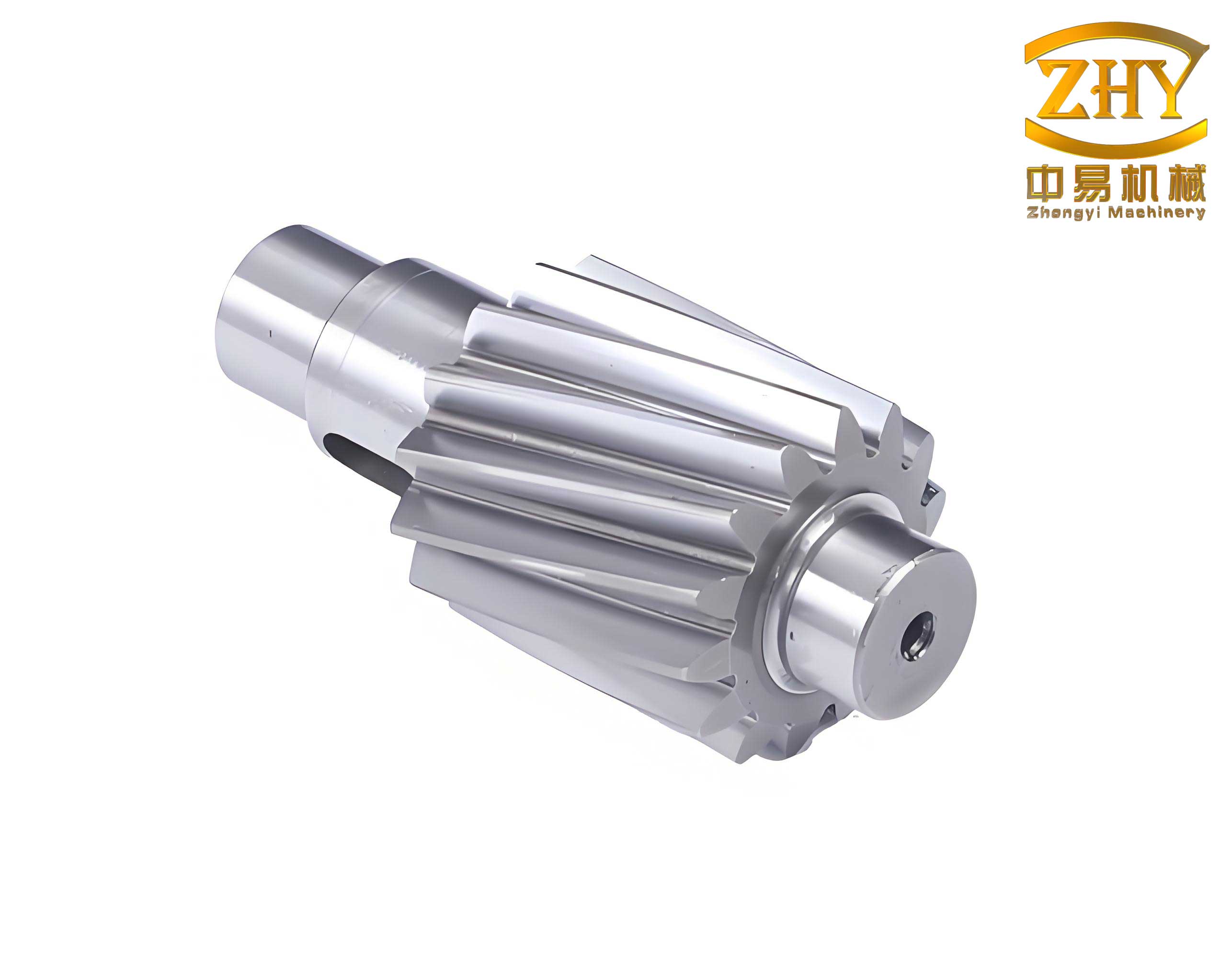
Another critical stress concentration site is the root of the keyway. The gear shaft is subjected to combined loading: torsion from the transmitted torque and bending from the gear mesh forces. The keyway further weakens the cross-section. The bending stress ($\sigma_b$) at the keyway root can be significant:
$$ \sigma_b = \frac{32 M}{\pi d^3} K_f $$
Where $M$ is the bending moment and $K_f$ is the fatigue stress concentration factor for the keyway. The combined stress state at this point makes it a prime location for crack initiation if not properly manufactured and heat-treated.
1.2 Material Deficiencies and Substandard Heat Treatment
The specified material for a high-speed gear shaft is chosen for its specific mechanical properties, such as high strength, toughness, and hardenability. A common and dangerous practice is material substitution without proper verification. For instance, replacing a designated alloy steel like 42CrMo with a plain carbon steel like C50 (or AISI 1050) has severe consequences.
Metallurgical analysis reveals the stark difference. A properly quenched and tempered 42CrMo gear shaft exhibits a microstructure of tempered martensite or fine bainite, providing an excellent combination of strength and toughness. The yield strength ($\sigma_y$) and toughness ($K_{IC}$) are high. Conversely, a C50 steel gear shaft may show a microstructure of proeutectoid ferrite and pearlite, or worse, Widmanstätten ferrite if overheated during forging or heat treatment. This structure drastically reduces impact toughness and fatigue resistance.
The core mechanical properties can be summarized in the following table:
| Material | Typical Microstructure | Tensile Strength (MPa) | Yield Strength (MPa) | Impact Toughness (J) | Fatigue Endurance Limit (MPa) |
|---|---|---|---|---|---|
| 42CrMo (Properly HT) | Tempered Martensite/Sorbit | ≥ 1080 | ≥ 930 | ≥ 63 | ~500-550 |
| C50 (Normalized) | Ferrite + Pearlite | ≈ 700 | ≈ 350 | ≈ 25 | ~300-350 |
| C50 (Overheated) | Widmanstätten Structure | ≈ 680 | ≈ 320 | < 15 | ~250-300 |
The fatigue life ($N_f$) is highly sensitive to the endurance limit ($\sigma_e$) and the applied stress range ($\Delta \sigma$), often modeled by Basquin’s law:
$$ \Delta \sigma = \sigma_f’ (2N_f)^b $$
Where $\sigma_f’$ is the fatigue strength coefficient and $b$ is the fatigue strength exponent. A lower endurance limit directly leads to a shorter fatigue life for the same operating stress. A gear shaft made from substandard material will fail prematurely even under designed loads.
2. Case Study: Rotary Kiln Reducer Failure Analysis
I was involved in investigating a recurring failure at a steel plant’s rotary kiln line. Four identical kilns were commissioned in 2012. The main drive consisted of a main motor (160 kW, 980 rpm) connected via a flexible coupling to a primary reducer (ratio 80:1), which drove the kiln via a pinion and girth gear. An auxiliary motor (18.5 kW, 1470 rpm) provided slow-turning capability via a secondary reducer (ratio 28:1).
2.1 Failure Sequence and Observations
In March 2015, abnormal vibration and noise were detected from the main reducer of one kiln. Online vibration monitoring showed no definitive spectral clues initially. The symptoms worsened, and upon shutdown and inspection, four broken teeth were found on the high-speed pinion gear shaft. During the subsequent cool-down period using the auxiliary drive, the gear shaft snapped completely.
Fracture Analysis:
The shaft fracture occurred at the shoulder of the M-M截面 (115 mm diameter), with a specified fillet radius of only 3 mm. The fracture surface was perpendicular to the axis, exhibiting multiple fatigue origins at the surface of the fillet, progression zones with beach marks, and a final fast fracture zone. The gear teeth fractures were of two types:
- Teeth 1 & 2 (Adjacent): Showed classic contact fatigue spalling and subsurface cracking, with internal锈点 indicating material defects.
- Teeth 3 & 4 (Spaced): Exhibited clean, brittle fracture surfaces characteristic of instantaneous overload, likely caused by the sudden misalignment after the initial teeth failed and the subsequent shaft fracture.
This indicated a progressive failure: material/contact fatigue initiated failure in two teeth, leading to dynamic imbalance and shock loading, which broke two more teeth and ultimately drove the疲劳 crack in the gear shaft to critical failure.
2.2 Quantitative Stress and Safety Analysis
To understand why the gear shaft failed, I performed a stress analysis on the critical M-M截面 under both driving conditions. The gear mesh forces (tangential $F_t$, radial $F_r$, axial $F_a$) were calculated from the transmitted power and geometry.
1. Main Motor Drive: Only bending moments are significant at the M-M截面.
$$ M_{H} = 1110 \, \text{N·m}, \quad M_{V} = 2479 \, \text{N·m} $$
The resultant bending moment is:
$$ M_{res} = \sqrt{M_{H}^2 + M_{V}^2} = 2716 \, \text{N·m} $$
Adding a conservative estimate for附加圆周力 effects, the maximum moment is:
$$ M_{max, main} \approx 2980 \, \text{N·m} $$
The alternating bending stress is:
$$ \sigma_{a, main} = \frac{32 M_{max, main} K_f}{\pi d^3} $$
2. Auxiliary Motor Drive (for cool-down): This is a more severe case with significant bending and torsion.
$$ M_{H} = 3233 \, \text{N·m}, \quad M_{V} = 8002 \, \text{N·m} $$
$$ M_{res} = \sqrt{M_{H}^2 + M_{V}^2} = 8630 \, \text{N·m} $$
With附加圆周力:
$$ M_{max, aux} \approx 9976 \, \text{N·m} $$
The transmitted torque is:
$$ T_{aux} = 4543 \, \text{N·m} $$
The alternating bending stress ($\sigma_a$) and mean torsional stress ($\tau_m$) are calculated accordingly.
3. Fatigue Safety Factor Evaluation: The fatigue safety factor ($n$) for combined bending and torsion is given by the von Mises criterion modified for fatigue:
$$ \frac{1}{n^2} = \left( \frac{\sigma_a}{S_e} \right)^2 + \left( \frac{\tau_m}{S_{sy}} \right)^2 $$
Where $S_e$ is the corrected endurance limit of the gear shaft material and $S_{sy}$ is the shear yield strength. The key variable is the fatigue stress concentration factor $K_f$, which depends heavily on the fillet radius ($r$).
I calculated the safety factors for the two scenarios:
| Drive Condition | Fillet Radius (r) | Calculated Safety Factor (n) | Allowable Safety Factor | Status |
|---|---|---|---|---|
| Main Motor | 3 mm | 4.72 | ≥ 1.5 – 2.0 | Acceptable |
| Auxiliary Motor | 3 mm | 1.33 | Unacceptable | |
| Auxiliary Motor | 10 mm (Corrected) | 1.98 | Acceptable |
The analysis conclusively showed that the original design with a 3 mm fillet radius was inadequate for the stresses encountered during auxiliary drive operation. The safety factor fell below the acceptable threshold, guaranteeing fatigue failure over time. This was the root cause of the gear shaft fracture. The transition on the gear shaft was a critical design flaw.
3. Integrated Countermeasures to Prevent Gear Shaft Failure
Based on this analysis and similar incidents, preventing fractures in the high-speed gear shaft requires a multi-faceted approach focusing on design, material, and process control.
1. Robust Design and Specification Review:
- Minimize Stress Concentrations: Mandate generous fillet radii and smooth transitions. For shaft shoulders, the fillet radius should be at least $r \ge 0.05d$ to $0.1d$. Perform FEA during design to identify high-stress areas in the gear shaft.
- Auxiliary Drive Analysis: Specifically analyze the gear shaft and system for the unique load conditions (high torque at low speed, potential for shock) during slow-drive operations. The gear shaft must be designed for the worst-case scenario.
2. Stringent Material and Manufacturing Controls:
- Material Certification: Enforce strict material traceability. Require mill certificates and perform independent spectrographic analysis on incoming gear shaft forgings to verify chemistry against specification (e.g., 42CrMo vs. C50).
- Microstructural Quality: Specify and audit heat treatment processes (quenching & tempering) to achieve the required microstructure and hardness profile throughout the gear shaft. Reject components showing Widmanstätten or other deleterious structures.
- Non-Destructive Testing (NDT): Implement mandatory NDT for all finished gear shafts. This should include Magnetic Particle Inspection (MPI) or Ultrasonic Testing (UT) to detect surface and subsurface defects in the gear shaft before assembly.
3. Enhanced Operational and Maintenance Practices:
- Condition Monitoring: Employ advanced vibration analysis with trending capabilities. Monitor parameters like spectral peaks (especially at gear mesh frequency and sidebands), and time-domain shock pulses. Early detection of pitting on the gear shaft teeth can prevent catastrophic failure.
- Alignment and Lubrication: Maintain precise alignment between the motor, reducer, and kiln to avoid imposing excessive bending moments on the gear shaft. Use the specified grade of extreme-pressure lubricant and monitor its cleanliness and condition.
- Proactive Replacement: Based on the fatigue life calculations and historical data, consider proactive replacement of critical gear shafts during major planned shutdowns, well before their predicted end of life.
4. Conclusion
Fractures in the high-speed gear shaft of reducers are complex failures rarely attributable to a single cause. They typically arise from the convergence of several factors: a design susceptible to stress concentration, the use of substandard or improperly heat-treated material for the gear shaft, and operational loads that exceed the design assumptions for certain modes like auxiliary driving. The case study clearly demonstrates how a seemingly minor design detail—an undersized fillet radius—can render a gear shaft critically unsafe under specific operating conditions, leading to sequential tooth and shaft failures.
Preventing such failures requires a disciplined, knowledge-based approach encompassing the entire lifecycle of the gear shaft, from design specification and supplier qualification to manufacturing oversight, proper installation, and intelligent condition-based maintenance. By addressing the root causes—structural, material, and operational—the reliability of the drive system can be significantly enhanced, ensuring the continuous and profitable operation of critical equipment like rotary kilns.