
In my experience with heavy machinery manufacturing, gear shafts are critical components that transmit torque and motion in various industrial applications. The integrity of these gear shafts is paramount, as failures can lead to significant downtime and safety hazards. Recently, I encountered a case involving an output gear shaft made of 18CrNiMo7-6 steel that developed a crack after carburizing and heat treatment. This incident prompted a detailed investigation to understand the root cause and prevent future occurrences. Gear shafts, especially those subjected to high loads, require meticulous material selection and processing to ensure reliability.
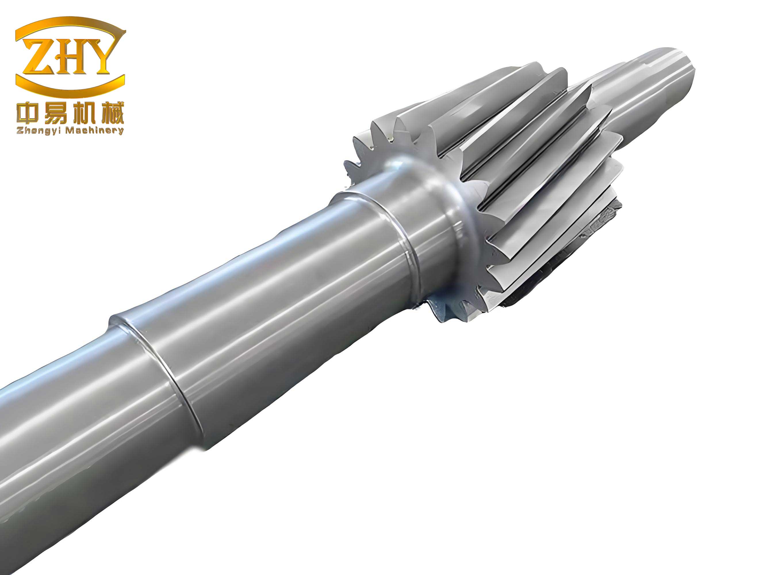
The output gear shaft in question had a gear section with dimensions of φ238 mm × 130 mm and a total length of 505.5 mm. The material, 18CrNiMo7-6 steel, is commonly used for high-strength gear shafts due to its excellent hardenability and toughness. The manufacturing process included forging, normalizing, rough machining, quenching and tempering, finish machining, gear cutting, carburizing, quenching and tempering again, spline forming, and gear grinding. The heat treatment regimen involved carburizing at 920°C to achieve a surface carbon content of 1.1%, followed by diffusion at 920°C to 0.90% C, and then quenching from 820°C at 0.75% C into oil at 80°C. A secondary quenching was performed at 810°C for 6 hours with oil cooling at 60°C, and finally tempering at 220°C for 10 hours with air cooling. Out of a batch of 12 gear shafts processed together, only one exhibited a crack after treatment, detected via ultrasonic testing.
The crack was longitudinal, extending approximately 390 mm from the small end face to the gear large end face. It varied in width, being widest (about 2 mm) near the small end and narrowing toward the gear section. Radially, from the small end face with a diameter of φ110 mm, the crack penetrated about 68 mm deep, tapering from the surface to the core. Additionally, a minor axial crack of 7 mm length was observed on the outer diameter, 21 mm from the small end and 70 mm from the main crack. Such anomalies in gear shafts necessitate thorough analysis to safeguard performance.
To analyze the crack morphology, I examined transverse and fracture surfaces. Macroscopically, the crack appeared straight in non-coated areas and jagged where anti-seepage coating was applied. The fracture surface revealed distinct zones: a flat region with oxide scale (indicating pre-tempering initiation), a river pattern area (propagation zone), another flat region (secondary crack initiation), and a radial pattern zone (secondary propagation). These features suggest multiple cracking events, possibly linked to inherent material flaws or processing stresses in gear shafts.
I conducted several tests to quantify the crack’s characteristics. Hardness measurements were taken from the surface to the core near the crack and on a gear tooth sample. The results, summarized in Table 1, show lower hardness near the surface due to anti-seepage coating and higher hardness adjacent to the crack due to carburization. This gradient underscores the role of heat treatment in altering material properties in gear shafts.
| Location | Distance from Surface (mm) | Distance from Crack (mm) | Hardness (HRC) |
|---|---|---|---|
| Crack Sample (A-side) | 2.4 | 30.0 | 38.4 |
| 6.0 | 27.5 | 43.3 | |
| 9.8 | 24.3 | 48.3 | |
| 13.8 | 21.2 | 48.3 | |
| 17.4 | 19.4 | 46.3 | |
| 22.0 | 17.0 | 46.1 | |
| 27.5 | 14.5 | 42.1 | |
| 32.0 | 11.2 | 43.6 | |
| 38.0 | 6.3 | 53.0 | |
| 44.0 | 4.3 | 54.2 | |
| Crack Sample (B-side) | 3.7 | 37.3 | 35.7 |
| 8.4 | 32.6 | 37.6 | |
| 13.3 | 28.5 | 45.4 | |
| 19.6 | 24.0 | 47.0 | |
| 22.4 | 20.7 | 44.2 | |
| 26.7 | 16.6 | 43.8 | |
| 31.5 | 12.6 | 43.7 | |
| 37.2 | 8.1 | 44.5 | |
| 41.0 | 4.9 | 50.6 | |
| 45.0 | 2.7 | 53.9 | |
| Gear Tooth Sample | 6.6 | N/A | 42.0 |
| 10.0 | N/A | 40.9 | |
| 13.3 | N/A | 39.6 | |
| 16.8 | N/A | 39.0 | |
| 20.4 | N/A | 38.2 | |
| 24.0 | N/A | 38.7 | |
| 27.3 | N/A | 37.7 | |
| 30.7 | N/A | 36.7 |
Metallographic examination revealed that the crack initiated in areas with heavy non-metallic inclusions, as shown in transverse and longitudinal samples. The inclusions were elongated and distributed along the outer circumference, acting as stress concentrators. The microstructure near the crack included fine martensite, retained austenite, and minor carbides at the surface, transitioning to lath martensite deeper in. The effective case depth was measured at 2.20 mm, consistent with carburizing specifications for gear shafts. On the gear tooth sample, the case depth was 2.15 mm with carbides at level 1, martensite at level 2, and retained austenite below 20%, indicating proper heat treatment except for the flawed region.
Chemical analysis confirmed that the material composition met the EN-10084 standard for 18CrNiMo7-6 steel, as detailed in Table 2. Thus, the issue was not due to off-spec chemistry but likely related to microstructural defects in the gear shafts.
| Element | Standard Range (EN-10084) | Measured Value | Status | ||||
|---|---|---|---|---|---|---|---|
| C | 0.15-0.21% | 0.19% | 合格 | ||||
| Si | 0.15-0.40% | 0.26% | 合格 | ||||
| Mn | 0.6-0.9% | 0.56% | 合格 | ||||
| P | ≤0.014% | 0.013% | 合格 | ||||
| S | ≤0.003% | 0.002% | 合格 | ||||
| Cr | 1.5-1.8% | 1.58% | 合格 | ||||
| Mo | 0.25-0.35% | 0.28% | 合格 | Ni | 1.4-1.7% | 1.49% | 合格 |
To understand the cracking mechanism, I considered the thermal stresses during quenching. The cooling rate in oil can induce significant thermal gradients, leading to stresses that may exacerbate pre-existing defects. The stress intensity factor \(K_I\) for a surface crack in a cylindrical gear shaft can be approximated by:
$$K_I = \sigma \sqrt{\pi a} \cdot f\left(\frac{a}{d}\right)$$
where \(\sigma\) is the applied stress, \(a\) is the crack depth, \(d\) is the shaft diameter, and \(f(a/d)\) is a geometric correction factor. For gear shafts under torsional loading, the shear stress \(\tau\) contributes to crack propagation. The equivalent von Mises stress during quenching can be expressed as:
$$\sigma_{eq} = \sqrt{\frac{(\sigma_r – \sigma_t)^2 + (\sigma_t – \sigma_z)^2 + (\sigma_z – \sigma_r)^2}{2}}$$
where \(\sigma_r\), \(\sigma_t\), and \(\sigma_z\) are radial, tangential, and axial stresses, respectively. These stresses arise from temperature differentials \(\Delta T\) during cooling, which can be modeled using Fourier’s law of heat conduction:
$$\frac{\partial T}{\partial t} = \alpha \nabla^2 T$$
with \(\alpha\) as thermal diffusivity. For gear shafts, the quenching process often follows a non-linear cooling curve, which I approximate with an exponential decay:
$$T(t) = T_0 + (T_q – T_0) e^{-\beta t}$$
where \(T_0\) is initial temperature, \(T_q\) is quenchant temperature, and \(\beta\) is a cooling rate constant. The resulting thermal strain \(\epsilon_{th}\) is:
$$\epsilon_{th} = \alpha_T \Delta T$$
with \(\alpha_T\) as the coefficient of thermal expansion. When constrained, this strain induces stress, potentially exceeding the material’s yield strength \(\sigma_y\) and initiating cracks at inclusion sites. The presence of inclusions reduces the effective fracture toughness \(K_{IC}\) of gear shafts, making them susceptible to quench cracking. The interaction between inclusions and matrix can be described using Eshelby’s inclusion theory, where the stress field around an ellipsoidal inclusion modifies local stress concentrations.
In this case, the crack initiated during the initial quenching and tempering stage, as evidenced by oxide scale on part of the fracture surface. The secondary crack propagated during carburizing and final quenching, driven by residual stresses and inclusion-induced stress concentrations. The jagged morphology in coated areas suggests that anti-seepage coating altered the cooling rate, leading to complex stress states. For gear shafts, such coatings are applied to prevent carburization on non-gear sections, but they can create thermal gradients that promote cracking if defects are present.
To mitigate such issues, I recommend enhanced material screening for gear shafts. Non-destructive testing (NDT) methods like ultrasonic inspection should be employed before heat treatment to detect inclusions. Additionally, optimizing quenching parameters can reduce thermal stresses. The cooling rate can be controlled by adjusting oil temperature and agitation, as described by the heat transfer coefficient \(h\) in Newton’s law of cooling:
$$q = h (T_s – T_q)$$
where \(q\) is heat flux and \(T_s\) is surface temperature. A lower \(h\) value, achieved through higher oil temperatures or reduced agitation, can decrease thermal gradients in gear shafts. Furthermore, finite element analysis (FEA) can simulate stress distributions during quenching, aiding in design improvements. The von Mises stress can be computed numerically to identify critical regions in gear shafts.
Another aspect is the material’s hardenability, which for 18CrNiMo7-6 steel can be assessed using the ideal critical diameter \(D_I\) formula:
$$D_I = D_{base} \times f_{Mn} \times f_{Si} \times f_{Cr} \times f_{Mo} \times f_{Ni}$$
where \(f\) are multiplicative factors for alloying elements. This helps predict the depth of hardening in gear shafts, ensuring uniform properties. In this case, the measured hardness profile aligns with expected hardenability, but inclusions disrupted homogeneity.
In conclusion, the crack in the output gear shaft was primarily caused by non-metallic inclusions within the material, which acted as initiation sites for quench cracks during heat treatment. The combination of thermal stresses from quenching and the presence of these defects led to progressive cracking, as confirmed by morphological and metallurgical analysis. Gear shafts must be fabricated from high-quality steel with minimal inclusions to withstand rigorous processing. Future measures should include stringent material certification, pre-heat treatment NDT, and optimized quenching protocols to enhance the durability of gear shafts. This case underscores the importance of holistic quality control in manufacturing critical components like gear shafts, where even minor defects can lead to catastrophic failures.
Reflecting on this analysis, I emphasize that gear shafts are backbone elements in power transmission systems, and their reliability hinges on integrated material and process engineering. Continued research into advanced steel grades and heat treatment technologies will further improve the performance of gear shafts in demanding applications.