
The evolution of product design and manufacturing in the information age is fundamentally driven by concepts of concurrency, integration, and agility, aiming for a highly automated, lifecycle-oriented process. This paradigm shift stands in stark contrast to traditional, localized, and sequential design methodologies. For mechanical components as ubiquitous and computationally intensive as the screw gear pair, this necessitates a new model: network-based design and manufacturing. This approach leverages shared resources, enables collaborative work, and significantly accelerates the design cycle, marking an essential step towards informatization and automation in engineering. In this article, I will explore an architectural framework and implementation methodology for such a network-oriented screw gear design system, demonstrating how traditional calculations can be transformed into efficient, web-based processes.
The screw gear drive, typically operating at a 90° shaft angle, is renowned for its high transmission ratio, compactness, smooth operation, and potential for self-locking. However, its design process is notoriously complex, hampered by low efficiency and the need for expensive bearing materials. The traditional design loop involves iterative calculations, extensive manual retrieval from standardized tables and charts, and repetitive verification checks. This process is not only time-consuming and prone to error but also constitutes a significant bottleneck. While computer-aided design software has alleviated some of these burdens, most solutions remain confined to standalone desktop applications. The true potential for efficiency and collaboration lies in migrating this process to a networked environment, enabling parameterized screw gear design to be performed efficiently within an intranet or over the internet.
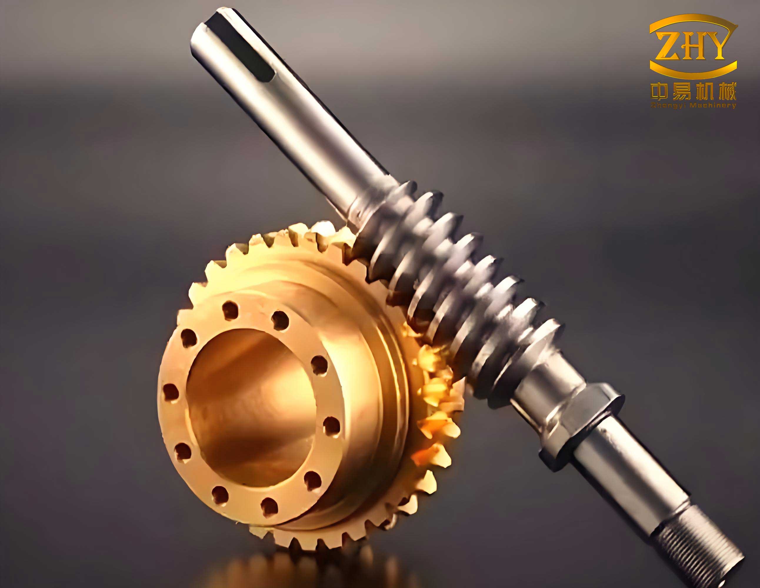
The core challenge in creating such a system lies in the effective sharing of diverse and often dispersed design resources. In mechanical design, these resources include design standards, specifications for standard and common parts, technical documentation, 2D/3D digital models, material databases, and manufacturing process information. These exist in various formats—text files, databases, and proprietary CAD model files—across different departments. A functional network-based system must provide a unified framework for accessing and utilizing these heterogeneous resources. To address this, I propose a three-tier Browser/Server (B/S) architecture as the foundational model for resource sharing and system operation.
This B/S architecture decouples the user interface, application logic, and data storage into distinct layers, promoting scalability and ease of maintenance. The system model, integrating both Internet and Intranet protocols, can be visualized as follows:
System Operation in a Three-Tier B/S Model:
1. Presentation Tier (Client Browser): The user interacts with the system via a standard web browser, eliminating the need for specialized client-side software. Requests are made through intuitive web forms.
2. Application Logic Tier (Web Server): This is the system’s engine. Upon receiving a client request, the web server executes the relevant application scripts. These scripts handle business logic, such as initiating a screw gear design calculation. Crucially, they act as an intermediary, invoking specialized software components and querying databases.
3. Data Tier (Database Server): This layer manages all persistent data, including user input parameters, standard lookup tables (e.g., for material properties, tooth form coefficients), pre-defined calculation routines, archived design results, and digital model files.
The operational flow is seamless: a request from the browser is processed by the web server, which runs applications, queries the database, and dynamically generates an HTML page with the results (e.g., calculated gear dimensions, a design report, or a link to a generated drawing) sent back to the browser.
The implementation of this model, particularly for a computationally driven task like screw gear design, relies on a synergistic combination of key web technologies: Active Server Pages (ASP), Component Object Model (COM) components, and networked databases.
ASP (Active Server Pages) serves as the critical server-side scripting environment. It is not a language itself but a framework that allows HTML pages to be infused with server-side scripts (e.g., VBScript, JScript). When a browser requests an ASP page, the web server executes the embedded scripts before sending the final HTML to the client. This enables the creation of dynamic, interactive web applications. The power of ASP in an engineering context, however, is vastly amplified by its ability to instantiate and manipulate pre-compiled software components—COM objects.
COM (Component Object Model) Technology is the cornerstone for encapsulating complex engineering logic. A COM component is a binary, reusable software module that exposes its functionality through defined interfaces (properties and methods). For a screw gear design system, the core calculation engine—encompassing geometry derivation, strength checks (bending and contact stress), efficiency calculation, and thermal rating—is developed as a COM component, typically using a language like Visual Basic or C++ for rapid development and robustness.
The relationship is pivotal: ASP provides the web interface and control flow, while the COM component provides the deep engineering computational power. The ASP script acts as a controller, collecting user input from a web form, validating it, passing it to the instantiated screw gear COM object, triggering its calculation methods, and retrieving the results for presentation. This separation offers tremendous advantages:
- Language Independence: The COM component can be written in the most suitable language, while ASP handles the web presentation.
- Binary Reusability & Performance: The compiled component runs faster than interpreted script and can be reused across different applications (e.g., a standalone desktop tool and the web system).
- Security & Intellectual Property: The core algorithms are protected within the binary component, safeguarding proprietary design knowledge.
Network Database Technology (e.g., Microsoft SQL Server, MySQL) binds the system together. It moves beyond simple file storage to offer robust, secure, and concurrent access to all design data. Database tables store user profiles, session data, input parameters for each design job, calculated results, and metadata linking to generated files. This centralized data management is essential for tracking design history, facilitating collaboration, and ensuring data integrity and security across the networked platform.
The practical application of this framework is best illustrated through a developed prototype system for the parameterized design of screw gear pairs. The system flow follows a logical sequence from input to final output, leveraging all aforementioned technologies.
Stage 1: Parameter Input & Storage. A user logs in via the browser and navigates to the screw gear design module. An ASP-generated form presents relevant input fields. A typical set of primary design inputs is collected, as summarized below:
| Input Parameter Group | Examples | Typical Values/Source |
|---|---|---|
| Power & Kinematic Requirements | Input Power (P), Input Speed (n1), Desired Ratio (i) | P=5.5 kW, n1=1450 rpm, i=20 |
| Material Selection | Worm Material, Worm Wheel Material Grade | Case-hardened Steel, Tin Bronze |
| Preliminary Geometry Choices | Number of Worm Threads (z1), Diameter Factor (q) | z1=2 or 4, q chosen from standard series |
| Design Coefficients | Application Factor (KA), Tooth Load Distribution Factor | KA from application table (e.g., 1.0 for uniform load) |
Upon submission, an ASP script validates the data and executes an SQL command to store this input set in a dedicated table within the network database, creating a unique job record.
Stage 2: Core Design Computation via COM. The ASP script then proceeds to the heart of the process. It creates an instance of the screw gear design COM component. The stored input parameters are fetched from the database and passed to the component’s properties. A method like CalculateGearGeometry() is invoked. Inside this compiled component, the full iterative design procedure is executed. This includes determining the center distance ‘a’, which is a fundamental and iterative calculation. The initial estimate often follows a power-based formula:
$$ a \geq K_a \cdot \sqrt[3]{P_2 / (n_2 / 9550)^2} $$
where \( K_a \) is a material-dependent coefficient, \( P_2 \) is the output power (considering an assumed efficiency), and \( n_2 \) is the output speed. The component then calculates the worm reference diameter \( d_1 \), the worm wheel diameter \( d_2 \), module \( m \), and other geometric features, checking against constraints and standard values at each step.
Stage 3: Strength Verification & Optimization. The COM component automatically performs the critical strength checks. The contact stress on the worm wheel teeth is calculated using a refined formula, which considers the geometry of the screw gear pair:
$$ \sigma_H = Z_E \cdot Z_\rho \cdot \sqrt{ \frac{9.55 \times 10^6 \cdot K_A \cdot T_2 \cdot K_\beta}{d_1 \cdot d_2^2 \cdot m} } \leq [\sigma]_{H} $$
where \( Z_E \) is the elasticity coefficient, \( Z_\rho \) is the contact ratio factor, \( K_A \) is the application factor, \( K_\beta \) is the load distribution factor, \( T_2 \) is the torque on the worm wheel, and \( [\sigma]_{H} \) is the allowable contact stress for the wheel material. Similarly, bending stress is verified. If stresses exceed allowances, the component logic adjusts parameters (e.g., selects a larger module, increases center distance) and iterates the calculation until a safe and optimal design is converged upon. All intermediate and final results are packaged by the component.
Stage 4: Result Retrieval & Presentation. The ASP script retrieves the result set from the COM component. This data is both stored back in the database for the user’s job history and used to dynamically generate a detailed output HTML page. The results encompass multiple aspects of the finalized screw gear design.
| Parameter | Symbol | Value | Unit |
|---|---|---|---|
| Center Distance | a | 125.0 | mm |
| Axial Module | m | 5.0 | mm |
| Worm Reference Diameter | d1 | 50.0 | mm |
| Worm Wheel Pitch Diameter | d2 | 200.0 | mm |
| Number of Worm Threads | z1 | 2 | – |
| Number of Wheel Teeth | z2 | 40 | – |
| Lead Angle | γ | 11.31 | deg |
| Calculated Contact Stress | σ_H | 245 | MPa |
| Allowable Contact Stress | [σ]_H | 250 | MPa |
| Estimated Efficiency | η | 0.87 | – |
Furthermore, the system can invoke other processes. For instance, the final dimensions can be sent to a CAD automation service (e.g., using SolidWorks API) to generate a 3D digital model and associated 2D engineering drawings. Links to download these files in standard formats (STEP, IGES, DWG) are then provided on the results page. The entire process, from input submission to viewing results and drawings, occurs within the browser, demonstrating a complete web-based screw gear design cycle.
This network-oriented framework fundamentally transforms the screw gear design workflow. It centralizes and democratizes access to complex calculation tools and standardized data. Engineers in different locations can collaborate on the same design project, share results instantly, and maintain a common digital thread. The automation of iterative calculations and checks reduces human error and frees the designer to focus on higher-level decision-making and optimization. The integration of the COM component ensures computational reliability and performance that a purely script-based web application could not achieve. This approach is not limited to screw gear pairs but provides a scalable template for the network-based design of other complex mechanical components like spiral bevel gears, bearings, or springs.
Future advancements will integrate more deeply with Product Lifecycle Management (PLM) systems, incorporate artificial intelligence for initial parameter suggestion and optimization, and leverage cloud computing resources for extremely complex simulations (e.g., detailed thermal-structural analysis of the screw gear assembly) directly from the web interface. The prototype system validates the core premise: that through a thoughtful architecture combining B/S models, ASP, COM components, and network databases, traditional mechanical design processes can be effectively migrated to a shared, collaborative, and efficient networked environment, paving the way for the next generation of informed and agile mechanical design.