
In my extensive experience designing precision machinery, particularly for computer numerical control (CNC) applications, the challenge of transmitting motion accurately and reliably is paramount. While ball screws and gear trains are ubiquitous, there are compelling scenarios where the unique advantages of screw gears, or worm drives, are indispensable. This is especially true for applications like CNC rotary tables, where a high reduction ratio in a compact, right-angle configuration is required. However, the traditional reluctance to employ screw gears in servo-driven systems is well-founded. Their inherent drawbacks—significant wear, heat generation, and, most critically, the unavoidable and variable backlash—pose serious threats to system stability and rigidity. In open-loop or semi-closed loop systems, backlash creates dead zones, directly impacting positioning accuracy. In closed-loop systems, it introduces non-linearities that can challenge control algorithms and degrade performance. Over years of practical work, I have developed and refined a robust method to harness the benefits of screw gears while effectively neutralizing their greatest weakness: the split worm drive with integrated spring compensation. This article details this approach, its design principles, critical calculations, and successful implementation.
The core issue with conventional screw gears in precision drives is backlash, the play between the worm and worm wheel teeth. Over time, wear exacerbates this gap. Common methods for backlash elimination, such as dual-lead worms or twin worm assemblies, often prove complex, costly, and difficult to maintain. My solution centers on a fundamentally simple yet mechanically elegant concept: splitting the worm axially into two segments to allow continuous, spring-loaded engagement with the worm wheel. The system’s heart is a modified worm shaft. I design it as a splined shaft. One segment of the worm, which I term the fixed segment, is permanently keyed or pinned to this splined shaft. The adjacent segment, the floating segment, is free to slide along the spline. A pre-loaded compression spring assembly acts against this floating segment, pushing it axially so that its thread profile is forced into tight meshing contact with the worm wheel. The fixed segment provides the primary driving force. Together, under the spring’s influence, the two segments envelop the worm wheel teeth, effectively eliminating any clearance in the mesh. This configuration ensures that regardless of load direction or wear progression, the worm wheel teeth are always in contact with a driving flank, thereby eliminating reversal dead zone.
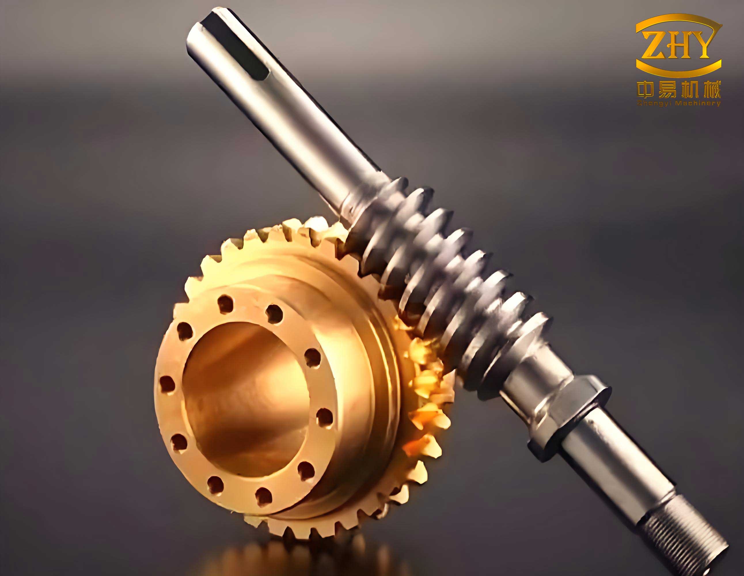
The kinematic and static analysis of this split worm drive is crucial for sizing the spring and predicting performance. The primary goal is to determine the required spring force \( F_s \) to maintain contact without inducing excessive bearing load or accelerated wear. This force must overcome the potential separation force generated during operation. A key parameter is the normal force \( F_n \) between the worm and wheel. For a worm transmitting torque \( T_w \), the tangential force at the worm pitch circle is \( F_t = \frac{2 T_w}{d_{w1}} \), where \( d_{w1} \) is the worm’s pitch diameter. The normal force can be approximated, considering the lead angle \( \gamma \) and pressure angle \( \alpha_n \), by:
$$ F_n \approx \frac{F_t}{\cos \alpha_n \cos \gamma – \mu \sin \gamma} $$
Here, \( \mu \) is the coefficient of friction. The axial component of the mesh force that tends to separate the floating segment is critical. The spring force \( F_s \) must be greater than this axial separation force \( F_{ax,sep} \). For a single-start worm, the relationship between tangential and axial force is \( F_{ax} \approx F_t \cdot \tan \gamma \). However, to ensure positive contact under dynamic conditions and account for wear over time, I apply a safety factor \( S_f \) (typically 1.5 to 2.5). Thus, the design spring force is:
$$ F_s = S_f \cdot K \cdot F_{ax,sep} $$
Where \( K \) is a factor accounting for the load distribution between the fixed and floating segments, often taken as 0.5 for initial design, assuming equal load sharing. The spring must also provide sufficient compensation travel \( \delta \) to account for anticipated wear over the system’s life. If the expected wear depth on the worm thread is \( \Delta \), the required spring travel is approximately \( \delta \approx \Delta / \sin \alpha_n \).
Material selection and manufacturing precision are non-negotiable for the success of this split worm drive system. The table below summarizes my standard specifications for critical components:
| Component | Recommended Material | Heat Treatment | Key Hardness | Critical Tolerance |
|---|---|---|---|---|
| Worm (both segments) | 38CrMoAlA (AISI 6470 equivalent) | Nitriding | 900-1000 HV | Lead error < 5 µm over 300 mm |
| Worm Wheel | Centrifugally Cast Tin Bronze (e.g., C90500) | None (cast state) | 80-90 HB | Tooth profile error < 10 µm |
| Splined Shaft | 42CrMo4 (AISI 4140 equivalent) | Quenched and Tempered | 45-50 HRC | Spline flank parallelism < 0.01 mm |
| Compression Spring | Chrome Vanadium Steel (SAE 6150) | Shot peened and stress relieved | N/A | Spring rate tolerance ±10% |
The manufacturing sequence is vital. The worm is first manufactured as a single piece, including all grinding and nitriding processes to achieve final accuracy and surface hardness. Only after these final finishing steps is the worm precisely cut into two segments using wire electrical discharge machining (EDM). The cut faces are then ground parallel to ensure smooth sliding and to remove a controlled amount of material, creating the necessary gap for spring action. This guarantees that the critical thread geometry is not compromised by the splitting operation.
Design parameters for the screw gears themselves must be optimized for CNC duty. I consistently apply the following guidelines, which can be summarized in a parameter selection formula table. The goal is to maximize stiffness, accuracy, and longevity.
| Parameter | Symbol | Design Guideline / Formula | Rationale |
|---|---|---|---|
| Number of Worm Starts | \( z_1 \) | Preferably 1; ≤ 3 for high-speed apps | Higher reduction per stage, better accuracy, less sensitivity to lead error |
| Worm Diameter Factor | \( q \) | Select as large as possible (\( q > 12 \)) | Increases worm stiffness (\( d_{w1} = m \cdot q \)), improves tool life and manufacturing accuracy |
| Module | \( m \) | Based on bending and wear strength: \( m \ge \sqrt[3]{\frac{2 K T_2 Y_F}{q z_2 \sigma_{FP}}} \) | Standardized values from strength calculation |
| Worm Wheel Diameter | \( d_{w2} \) | Maximize within space constraints | Improves kinematic accuracy, reduces specific sliding |
| Pressure Angle | \( \alpha_n \) | Reduce slightly (e.g., 20° to 17.5° or 15°) | Increases contact line length, improves smoothness, reduces sensitivity to radial runout |
| Center Distance | \( a \) | \( a = \frac{m (q + z_2)}{2} \) | Determined by \( m, q, z_2 \) |
| Lead Angle | \( \gamma \) | \( \gamma = \arctan(\frac{z_1}{q}) \) | Small for single-start, affects efficiency and axial forces |
In these formulas, \( K \) is the load factor, \( T_2 \) is the output torque on the worm wheel, \( Y_F \) is the form factor, and \( \sigma_{FP} \) is the allowable bending stress. The wear capacity check, often governing for bronze wheels, uses the specific sliding velocities and contact stress formula:
$$ \sigma_H = Z_E \sqrt{ \frac{F_n}{L_{min}} \cdot \frac{1}{\rho_{red}} } \le \sigma_{HP} $$
where \( Z_E \) is the elasticity factor, \( L_{min} \) is the minimum length of contact line, \( \rho_{red} \) is the reduced radius of curvature, and \( \sigma_{HP} \) is the permissible contact stress. For the split worm design, the continuous spring pressure slightly increases the mean load, so I use a 10-15% higher safety factor in the wear calculation compared to a standard drive.
The housing design incorporates several critical features. First, it must provide rigid support for the bearings. I exclusively use preloaded angular contact ball bearings for the worm shaft to eliminate axial play there. Secondly, the housing includes an accessible adjustment window sealed with a cover. This allows for the periodic inspection and re-adjustment of the spring preload via the two locknuts. Over years of operation, as wear slowly consumes the spring’s compensation travel, this feature allows restoration of optimal preload force without disassembling the entire drive. The housing geometry must also facilitate efficient heat dissipation, often incorporating cooling fins or calculated internal passages for oil circulation in high-duty cycles.
The performance of this split worm drive system can be quantified by its impact on system dynamics. In a CNC rotary table application, the most significant improvement is the drastic reduction of the reversal error, often measured in arc-seconds. For a standard screw gear pair, backlash might be several arc-minutes. With the spring-compensated split design, this error can be reduced to a stable value below 10 arc-seconds, primarily limited by the manufacturing precision of the gears and bearings, not by mesh clearance. The system’s stiffness, defined as the torque required to produce a unit angular deflection \( k_\theta = \Delta T / \Delta \theta \), sees substantial improvement because the spring maintains a pre-loaded state, effectively creating a unilateral constraint. The closed-loop bandwidth of the servo system can be increased as the non-linear backlash discontinuity is removed, leading to faster settling times and reduced following error.
Let’s consider a detailed design example for a CNC rotary table with a required output torque \( T_2 = 1200 \, \text{Nm} \) and a max speed of 10 rpm. Using a single-start worm (\( z_1 = 1 \)) and selecting \( q = 16 \), \( m = 5 \, \text{mm} \), we find the worm wheel teeth number \( z_2 = 120 \) for a 120:1 reduction ratio. The center distance is \( a = 0.5 \times 5 \times (16 + 120) = 340 \, \text{mm} \). The worm pitch diameter is \( d_{w1} = 5 \times 16 = 80 \, \text{mm} \). The input torque from the servo motor (considering efficiency \( \eta \approx 0.85 \) for bronze on steel) is \( T_1 = T_2 / (i \cdot \eta) = 1200 / (120 \cdot 0.85) \approx 11.76 \, \text{Nm} \). The tangential force on the worm is \( F_t = 2 \times 11.76 / 0.080 = 294 \, \text{N} \). With a lead angle \( \gamma = \arctan(1/16) \approx 3.576^\circ \), the nominal axial force is \( F_{ax} \approx 294 \times \tan(3.576^\circ) \approx 18.4 \, \text{N} \). Applying a safety factor \( S_f=2 \) and load share factor \( K=0.6 \), the design spring force becomes \( F_s = 2 \times 0.6 \times 18.4 \approx 22.1 \, \text{N} \). This seems small, but it must be maintained over the wear compensation travel. If we anticipate 0.1 mm of wear depth on the worm thread, with \( \alpha_n = 20^\circ \), the needed spring travel is \( \delta \approx 0.1 / \sin(20^\circ) \approx 0.29 \, \text{mm} \). A spring with a rate of \( k_{spring} = F_s / \delta \approx 76 \, \text{N/mm} \) would be suitable, preloaded to deliver 22.1 N at the installed length.
The advantages of this system extend beyond mere backlash elimination. By allowing the use of screw gears in precision CNC applications, it simplifies mechanical layouts. It enables direct, right-angle drives without intermediate bevel gears or complex belt systems. The maintenance is straightforward through the adjustment window. Furthermore, the spring compensation passively adapts to wear, providing a long service life while maintaining accuracy. In my implementations across dozens of rotary tables and specialized indexing heads, this design has consistently delivered positioning stability and repeatability that rivals far more expensive direct-drive or torque motor solutions, but with higher torque density and better cost-effectiveness for medium to high reduction ratios.
In conclusion, the split worm drive with integrated spring compensation is a highly effective and practical method to deploy screw gears in demanding CNC systems. It directly attacks the principal weakness of backlash with a robust, mechanically simple solution that is manufacturable with standard processes. The keys to success lie in meticulous attention to material selection, manufacturing sequence, geometric parameter optimization, and proper sizing of the compensation mechanism. This approach has proven itself in the field, offering designers a reliable tool to achieve high stiffness, excellent accuracy, and long-term stability in motion control applications where the unique benefits of screw gears are required. It transforms a traditionally problematic component into a precision asset for advanced mechanical systems.