
In my experience working with precision engineering, the demand for small module gears in compact instruments, meters, and electronic devices has grown significantly. These gears often require high accuracy, minimal rigidity, and complex designs. Traditional methods like gear hobbing or fine shaping are still used for soft-faced gears with hardness below HRC 35, but they present challenges such as dependency on cutter precision, grinding errors, and blade sharpness, leading to difficult adjustments, low efficiency, and inconsistent results. This is where gear shaving emerges as a transformative process. Gear shaving offers higher efficiency and lower cost, dramatically improving gear accuracy and reducing surface roughness. Moreover, gear shaving allows for profile modifications and compensation for heat treatment distortions, correcting errors from previous operations, thereby reducing noise, enhancing load capacity, and extending service life. In this article, I will delve into the principles, practices, and optimizations of gear shaving for small module gears, supported by formulas and tables to encapsulate key insights.
The fundamental principle of gear shaving revolves around the meshing of a straight-tooth cylindrical gear (the workpiece) and a helical cylindrical gear (the shaving cutter). Their rotational axes naturally form an included angle $\phi$. When the shaving cutter rotates actively and the workpiece follows passively, the cutter’s circumferential velocity $v$ decomposes into two component vectors: one perpendicular to the workpiece axis, $v_t$, and another parallel to the gear tooth direction, $v_a$. The perpendicular component $v_t$ drives the workpiece rotation, while the axial component $v_a$ induces sliding between the tooth surfaces. The shaving action primarily stems from this sliding motion. With zero-backlash meshing, the cutter’s cutting edges, under the influence of $v_a$, remove an extremely thin chip from the workpiece tooth surface, typically around 0.005 to 0.01 mm thick. Mathematically, if $v$ is the cutter speed and $\phi$ is the axis angle, we have:
$$v_t = v \cos \phi, \quad v_a = v \sin \phi$$
The sliding velocity $v_s$ responsible for material removal can be expressed as:
$$v_s = v_a \cdot \frac{\sin \phi}{\cos \beta}$$
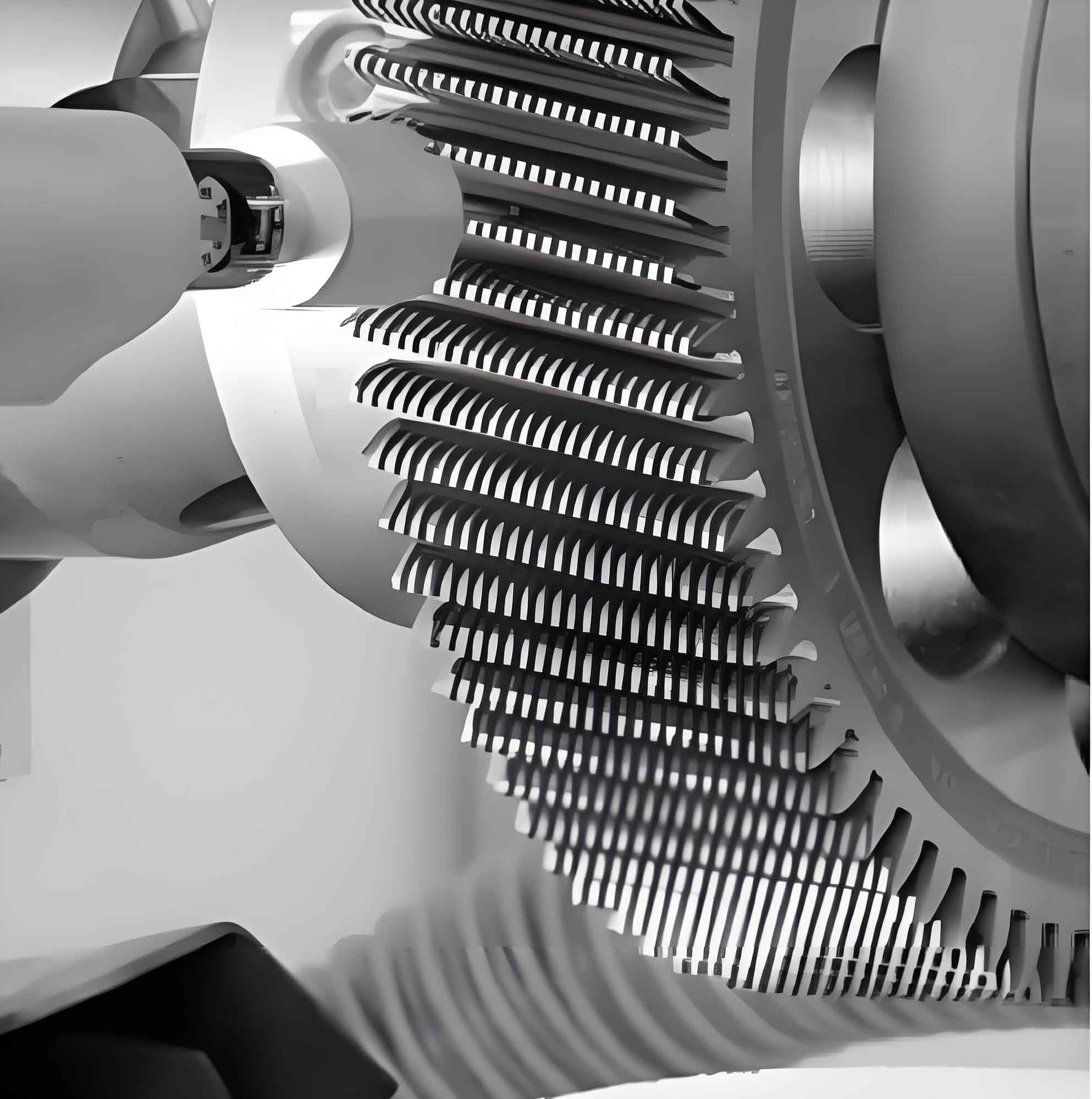
where $\beta$ is the helix angle of the shaving cutter. This interaction ensures precise finishing, but it’s crucial to understand that gear shaving is a free-rolling process, which can lead to instantaneous speed ratio variations and subsequent form errors. The contact between the shaving cutter and workpiece is not tangential but intersecting, forming a narrow contact zone whose major axis deviates from the workpiece’s line of action. This enables gear shaving to correct certain tangential errors, though it cannot address total composite error or pitch line runout. Additionally, the shaving cutter is essentially a modified gear with a pressure angle that differs from the workpiece, and the continuously changing center distance during shaving helps rectify profile and base pitch errors. To visualize this process, consider the following illustration of gear shaving in action:
For small module gears, the gear shaving process demands meticulous attention to gear blank accuracy. The blank serves as the foundation, and any imperfections here can propagate through the finishing stage. I recommend that the locating surfaces—such as bores or shafts—have minimal fit clearance, ideally around 0.005 mm, and concentricity within 0.003 to 0.004 mm. This reduces the impact of repeated clamping and prevents misjudgment during measurement due to datum errors. The selection of the shaving cutter is equally critical. According to the crossed-helical gear pair theory, any shaving cutter can be used if the normal base pitches match, but in practice, improper choices degrade quality. Therefore, verification is essential. The error in normal pressure angle should be limited to ±(1° to 2°), radial clearance to about 0.3 mm, and the cutter’s approach length $L_a$ should satisfy:
$$L_a \geq (0.5 \text{ to } 2.5) \cdot m_n / \tan \alpha_t$$
where $m_n$ is the normal module and $\alpha_t$ is the transverse pressure angle. This ensures the involute start point on the cutter is below that on the workpiece, preventing interference. Longitudinal gear shaving is typically employed, where the cutter traverses along the workpiece axis. The shaving allowance must be controlled; excessive allowance prolongs shaving time and may degrade accuracy. For small module gears, based on my observations, the following table summarizes key parameters:
| Parameter | Recommended Range for Small Module Gears (Module ≤ 1 mm) | Notes |
|---|---|---|
| Single-side shaving allowance | 0.005 – 0.01 mm | Dependent on module and prior gear accuracy |
| Root relief (undercut) | 0.0025 – 0.005 mm | Prevents interference and improves strength |
| Fit clearance for locating | 0.005 mm max | Ensures precise alignment |
| Concentricity tolerance | 0.003 – 0.004 mm | Critical for minimizing runout |
| Cutter approach length $L_a$ | (0.5 to 2.5) × $m_n$ / $\tan \alpha_t$ | Avoids incomplete profile generation |
| Axis angle $\phi$ | 10° – 20° | Balances cutting action and stability |
Error correction in gear shaving is a nuanced aspect. Since the process involves free rotation, workpiece speed fluctuations can occur, affecting the instantaneous gear ratio and increasing form error. To mitigate this, I emphasize the importance of maintaining consistent cutting conditions and using precise fixturing. The shaving cutter’s profile modifications play a key role in compensating for errors. For instance, to correct a profile deviation $\Delta f$, the cutter’s modified profile can be designed based on the error transfer function. The relationship between workpiece error $\Delta W$ and cutter correction $\Delta C$ can be approximated by:
$$\Delta W = K \cdot \Delta C \cdot \sin \phi$$
where $K$ is a process constant dependent on material and cutting parameters. Additionally, base pitch errors $\Delta p_b$ can be reduced if the normal base pitch condition is satisfied:
$$p_{bn,\text{cutter}} = p_{bn,\text{workpiece}} + \delta$$
where $\delta$ is a small tolerance, typically within ±0.002 mm. This ensures smooth meshing and reduces noise. The effectiveness of gear shaving in error correction is highlighted by its ability to improve gear accuracy by up to two grades, as per ISO standards, making it indispensable for high-precision applications.
Optimizing the gear shaving process involves addressing the inherent speed fluctuations. One approach is to implement controlled feed rates and damping mechanisms in the shaving machine. The dynamic model of the workpiece-cutter system can be described by a second-order differential equation:
$$I \ddot{\theta} + C \dot{\theta} + K \theta = T(t)$$
where $I$ is the moment of inertia, $C$ is the damping coefficient, $K$ is the stiffness, and $T(t)$ is the time-varying torque. Minimizing $\ddot{\theta}$ reduces speed variations, which can be achieved by optimizing $C$ and $K$ through machine design. Another optimization is in cutter design. The shaving cutter’s tooth geometry, including pressure angle and helix angle, should be tailored to the workpiece. For small module gears, a higher helix angle (e.g., 15° to 25°) enhances the sliding action but requires careful balance to avoid excessive axial forces. The cutter material also matters; typically, high-speed steel (HSS) or coated carbides are used, with hardness around HRC 62-64 to withstand wear. I often recommend using a break-in period for new cutters to stabilize performance.
In terms of process parameters, cutting speed, feed rate, and depth of cut are pivotal. For small module gear shaving, cutting speeds range from 50 to 150 m/min, feeds from 0.05 to 0.2 mm/rev, and multiple passes are used for consistent finish. Coolant selection is vital too; mineral-based oils with extreme pressure additives reduce friction and improve surface integrity. The table below outlines optimized parameters based on module size:
| Module (mm) | Cutting Speed (m/min) | Feed Rate (mm/rev) | Number of Passes | Coolant Type |
|---|---|---|---|---|
| 0.2 – 0.5 | 60 – 100 | 0.05 – 0.1 | 2 – 3 | Light mineral oil |
| 0.5 – 1.0 | 80 – 120 | 0.1 – 0.15 | 1 – 2 | EP additive oil |
| 1.0 – 1.5 | 100 – 150 | 0.15 – 0.2 | 1 | Synthetic coolant |
The benefits of gear shaving extend beyond accuracy. It significantly reduces surface roughness, typically achieving Ra values of 0.4 to 0.8 µm, compared to 1.6 to 3.2 µm from hobbing. This is due to the fine cutting action and multiple tooth engagements. Moreover, gear shaving induces compressive residual stresses on the tooth surface, enhancing fatigue resistance. The process is also economical for medium to high volumes, as it reduces the need for subsequent grinding. However, it’s not suitable for hardened gears (above HRC 40), where gear grinding becomes necessary.
To delve deeper into the mechanics, the contact pattern during gear shaving is elliptical, with the major axis length $a$ and minor axis length $b$ given by Hertzian contact theory. For two cylinders in crossed axes, the contact ellipse dimensions can be estimated as:
$$a = \sqrt[3]{\frac{3F(1-\nu^2)}{2E} \cdot \frac{R_1 R_2}{R_1 + R_2} \cdot \frac{1}{\cos^2 \phi}}, \quad b = \sqrt[3]{\frac{3F(1-\nu^2)}{2E} \cdot \frac{R_1 R_2}{R_1 + R_2} \cdot \cos \phi}$$
where $F$ is the normal force, $E$ is Young’s modulus, $\nu$ is Poisson’s ratio, and $R_1$, $R_2$ are the equivalent radii. This contact area influences the pressure distribution and material removal rate. In practice, adjusting the axis angle $\phi$ modifies the ellipse, affecting shaving efficiency. A larger $\phi$ increases $v_a$ and thus the sliding velocity, but may reduce contact stability. I often use $\phi = 15^\circ$ as a starting point for small module gears.
Another critical aspect is the alignment of the shaving cutter and workpiece. Misalignment can lead to asymmetric tooth flanks and increased noise. The tolerance for parallelism between axes should be within 0.01 mm over 100 mm length. Using precision collets or mandrels is essential. Additionally, the shaving machine’s stiffness plays a role; a rigid setup minimizes vibrations that could otherwise amplify errors. Regular maintenance of the machine, including checking spindle runout and guideways, ensures consistent gear shaving performance.
In terms of quality control, post-shaving inspection is vital. Key parameters include tooth profile, lead, pitch, and runout. Coordinate measuring machines (CMMs) or dedicated gear testers are used. For small module gears, non-contact optical methods are gaining popularity due to their precision. The improvement from gear shaving can be quantified by the reduction in error magnitudes. For instance, if the initial profile error is $\Delta f_0$, after shaving, it becomes:
$$\Delta f_{\text{final}} = \Delta f_0 \cdot e^{-k t}$$
where $k$ is a process constant and $t$ is shaving time. This exponential decay highlights the efficiency of gear shaving in error correction.
Looking ahead, advancements in gear shaving include CNC-controlled machines that allow real-time adjustments of axis angles and feeds, adaptive control based on sensor feedback, and the integration of simulation software to predict outcomes. For small module gears, micro-shaving techniques are being developed for modules below 0.2 mm, pushing the boundaries of miniaturization. The use of diamond-like carbon (DLC) coated cutters is also emerging to extend tool life and improve surface finish.
In conclusion, gear shaving is a highly effective finishing process for small module gears, offering superior accuracy, surface quality, and noise reduction compared to traditional methods. By understanding the principles, optimizing parameters, and addressing challenges like speed fluctuations, manufacturers can leverage gear shaving to produce high-performance gears for modern compact devices. The process’s ability to correct errors and enhance mechanical properties makes it a cornerstone in precision gear manufacturing. As technology evolves, continued refinement in gear shaving will further unlock potential in micro-engineering applications.
To summarize key formulas and parameters discussed, here is a consolidated table for quick reference in gear shaving applications:
| Aspect | Formula or Value | Description |
|---|---|---|
| Sliding velocity | $v_s = v \sin \phi / \cos \beta$ | Drives material removal |
| Normal base pitch condition | $p_{bn1} = p_{bn2} \pm \delta$ | Ensures proper meshing |
| Contact ellipse major axis | $a = \sqrt[3]{\frac{3F(1-\nu^2)}{2E} \cdot \frac{R_1 R_2}{R_1 + R_2} \cdot \frac{1}{\cos^2 \phi}}$ | Influences pressure distribution |
| Error correction decay | $\Delta f_{\text{final}} = \Delta f_0 \cdot e^{-k t}$ | Quantifies improvement over time |
| Recommended axis angle | $\phi = 10^\circ \text{ to } 20^\circ$ | Balances cutting and stability |
| Single-side allowance | 0.005 – 0.01 mm | For modules ≤ 1 mm |
| Surface roughness improvement | Ra: 0.4 – 0.8 µm after shaving | Vs. 1.6 – 3.2 µm from hobbing |
Through persistent application and innovation, gear shaving continues to be a vital process in the pursuit of perfection in gear technology. I encourage engineers to explore its full potential, especially for small module gears where precision is paramount.