
The process of **gear shaving** is a critical finishing operation for improving the geometric accuracy and surface quality of gear teeth. While extensively applied to external gears, the application of **gear shaving** to internal gears presents unique and complex challenges, primarily concerning the potential for interference between the shaving cutter and the internal gear workpiece. This article, from my perspective as a practitioner in gear engineering, delves into a detailed mathematical methodology for analyzing and preventing a specific type of interference—generative interference—during the **gear shaving** of internal gears, based on the principles of spatial meshing theory.
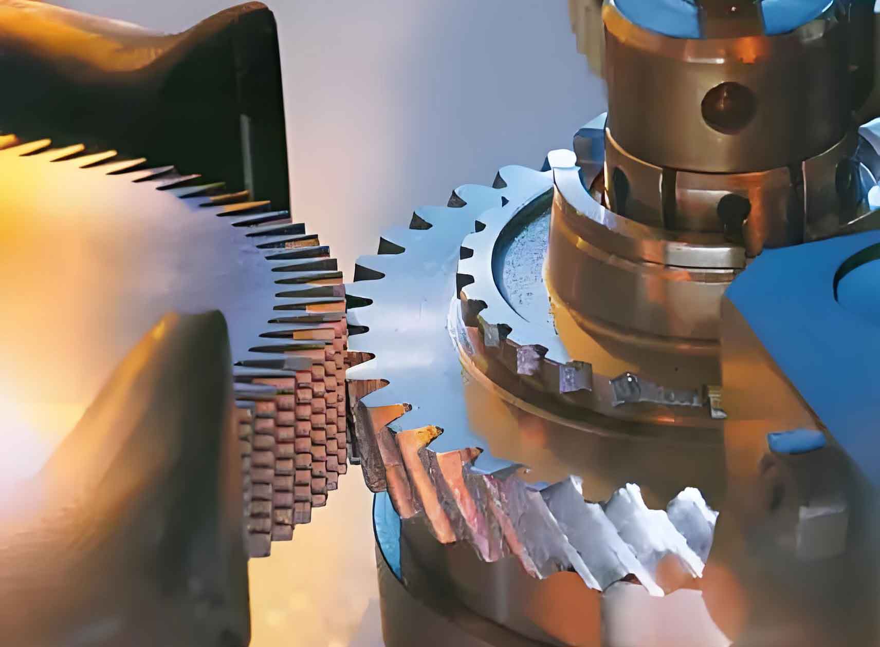
The **gear shaving** process for an internal gear can be fundamentally modeled as a spatial meshing problem between two helical gears with crossed axes. In such a configuration, three primary types of interference are theoretically possible, as outlined in the table below.
| Interference Type | Description | Relevance to Internal Gear Shaving |
|---|---|---|
| Type I: Tip-Root Interference | The tip of the cutter (pinion) interferes with the root fillet or transition curve of the internal gear. | Typically avoided. The internal gear’s root is often pre-undercut during the prior shaping or hobbing operation, creating clearance. |
| Type II: Root-Tip Interference | The tip of the internal gear interferes with the root fillet of the shaving cutter. | Generally not a concern. The shaving cutter is designed with sufficient root relief or a recess (shaving notch) to prevent this contact. |
| Type III: Generative (Peeling) Interference | During the meshing cycle, the tip of the cutter collides with the tip of the internal gear tooth before disengagement. | The primary and most critical concern for internal **gear shaving**. It is the focus of this analysis. |
Unlike internal gear shaping, which can be approximated by planar gearing models, **gear shaving** involves a crossed-axes configuration with complex relative screw motion. This spatial nature precludes the use of simple two-dimensional analysis and necessitates a robust three-dimensional mathematical model based on spatial gearing theory to accurately predict and prevent generative interference.
1. Development of the Mathematical Model for Interference Checking
The core of the analysis lies in constructing a mathematical framework to track the path of the shaving cutter’s tooth tip relative to the internal gear. The first step is to establish a coherent coordinate system network.
1.1 Coordinate Systems Setup
Two main coordinate systems are defined: one fixed to the workpiece (internal gear) and one fixed to the tool (shaving cutter). Their relationship is governed by the center distance \(a\) and the shaft crossing angle \(\Sigma\).
- Workpiece Systems: \(S_0 (O_0 – X_0 Y_0 Z_0)\) is the stationary system where the \(Z_0\)-axis coincides with the workpiece axis. \(S_2 (O_2 – X_2 Y_2 Z_2)\) is rigidly attached to and rotates with the workpiece, sharing the \(Z_2\)-axis with \(Z_0\).
- Tool Systems: \(S (O – X Y Z)\) is the stationary system for the tool, with the \(Z\)-axis aligned with the cutter axis. The \(X\)-axis of system \(S\) is collinear with the \(X_0\)-axis of system \(S_0\). \(S_1 (O_1 – X_1 Y_1 Z_1)\) is rigidly attached to and rotates with the shaving cutter, sharing the \(Z_1\)-axis with \(Z\).
The origins \(O\) and \(O_0\) are separated by the center distance \(a\). The workpiece axis (\(Z_0\)) and the tool axis (\(Z\)) are crossed at an angle \(\Sigma\).
1.2 Coordinate Transformation
When the shaving cutter rotates by an angle \(\phi_1\), the internal gear rotates by a corresponding angle \(\phi_2\), related by the gear ratio \(i_{12}\):
$$ i_{12} = \frac{\phi_1}{\phi_2} = \frac{z_2}{z_1} $$
where \(z_1\) and \(z_2\) are the number of teeth on the shaving cutter and the internal gear, respectively.
The transformation from the tool coordinate \(S_1\) to the workpiece coordinate \(S_2\) is given by:
$$ \mathbf{r}^{(2)} = \mathbf{M}_{z_0}^{-1}(\phi_2) \left[ \mathbf{M}_x(\Sigma) \mathbf{M}_z(\phi_1) \mathbf{r}^{(1)} + \mathbf{A} \right] $$
where \(\mathbf{r}^{(1)}\) and \(\mathbf{r}^{(2)}\) are position vectors in \(S_1\) and \(S_2\), \(\mathbf{A} = [a, 0, 0]^T\) is the center distance vector, and the transformation matrices are:
$$ \mathbf{M}_{z_0}^{-1}(\phi_2) = \begin{bmatrix}
\cos \phi_2 & \sin \phi_2 & 0 \\
-\sin \phi_2 & \cos \phi_2 & 0 \\
0 & 0 & 1
\end{bmatrix} $$
$$ \mathbf{M}_x(\Sigma) = \begin{bmatrix}
1 & 0 & 0 \\
0 & \cos \Sigma & -\sin \Sigma \\
0 & \sin \Sigma & \cos \Sigma
\end{bmatrix} $$
$$ \mathbf{M}_z(\phi_1) = \begin{bmatrix}
\cos \phi_1 & -\sin \phi_1 & 0 \\
\sin \phi_1 & \cos \phi_1 & 0 \\
0 & 0 & 1
\end{bmatrix} $$
We are interested in the trajectory of a point on the shaving cutter’s tooth tip. Consider a point \(Q\) on the tip edge, located in the tool’s mid-plane (where \(Z_1=0\)). Its coordinates in \(S_1\) are given by:
$$ \mathbf{r}_Q^{(1)} = \begin{bmatrix} x_1 \\ y_1 \\ 0 \end{bmatrix} = \begin{bmatrix} (d_{a1}/2) \cos \lambda_{a1} \\ (d_{a1}/2) \sin \lambda_{a1} \\ 0 \end{bmatrix} $$
where \(d_{a1}\) is the tip diameter of the shaving cutter, and \(\lambda_{a1}\) is the angular parameter defining the position of point \(Q\) on the tip circle in the mid-plane, related to the tip tooth thickness \(s_{a1}\).
Substituting \(\mathbf{r}_Q^{(1)}\) into the transformation equation yields the parametric equations (in parameter \(\phi_2\), with \(\phi_1 = i_{12}\phi_2\)) for the trajectory curve of point \(Q\) as seen in the workpiece coordinate system \(S_2\):
$$ \begin{aligned}
x_2(\phi_2) &= \frac{d_{a1}}{2} (\cos(i_{12}\phi_2)\cos\phi_2 + \sin\phi_2 \cos\Sigma \sin(i_{12}\phi_2)) \cos\lambda_{a1} \\
&- \frac{d_{a1}}{2} (\cos\phi_2 \sin(i_{12}\phi_2) – \sin\phi_2 \cos\Sigma \cos(i_{12}\phi_2)) \sin\lambda_{a1} + a \cos\phi_2 \\[6pt]
y_2(\phi_2) &= \frac{d_{a1}}{2} (-\cos(i_{12}\phi_2)\sin\phi_2 + \cos\phi_2 \cos\Sigma \sin(i_{12}\phi_2)) \cos\lambda_{a1} \\
&+ \frac{d_{a1}}{2} (\sin\phi_2 \sin(i_{12}\phi_2) + \cos\phi_2 \cos\Sigma \cos(i_{12}\phi_2)) \sin\lambda_{a1} + a \sin\phi_2 \\[6pt]
z_2(\phi_2) &= \frac{d_{a1}}{2} \sin\Sigma \sin(i_{12}\phi_2) \cos\lambda_{a1} + \frac{d_{a1}}{2} \sin\Sigma \cos(i_{12}\phi_2) \sin\lambda_{a1}
\end{aligned} $$
1.3 Condition for Generative Interference
To check for interference, we must determine if this spatial trajectory of the cutter’s tip comes too close to the internal gear’s tooth tip. We define a radial plane \(\sigma\) in the workpiece system \(S_2\) that contains both the \(Z_2\)-axis and the tip point \(B\) of the internal gear tooth. The equation of this plane is:
$$ y_2 = x_2 \tan \lambda_a $$
Here, \(\lambda_a\) is the angular half-thickness of the internal gear tooth tip space on the tip circle. It is calculated from the gear’s basic parameters, tip diameter \(d_{a2}\), tip tooth thickness \(s_{a2}\), and the desired shaving stock \(\delta\).
The condition for potential generative interference is that the spatial trajectory of point \(Q\) intersects this plane \(\sigma\) at a radial distance from the \(Z_2\)-axis that is greater than the internal gear’s tip radius \(R_{a2}\). If the intersection point is at a smaller radius, the cutter tip passes safely inside the gear tip; if it is at a larger radius, a collision (interference) occurs.
To find the intersection point \(E\), we substitute the expressions for \(x_2(\phi_2)\) and \(y_2(\phi_2)\) into the plane equation \(y_2 = x_2 \tan \lambda_a\). This results in a transcendental equation in the single parameter \(\phi_2\):
$$ \begin{aligned}
\frac{d_{a1}}{2} &[ -\sin\phi_2 \cos(i_{12}\phi_2) + \cos\phi_2 \cos\Sigma \sin(i_{12}\phi_2) ] \cos\lambda_{a1} \\
+ \frac{d_{a1}}{2} &[ \sin\phi_2 \sin(i_{12}\phi_2) + \cos\phi_2 \cos\Sigma \cos(i_{12}\phi_2) ] \sin\lambda_{a1} + a \sin\phi_2 \\
– \tan\lambda_a & \bigg\{ \frac{d_{a1}}{2} [ \cos(i_{12}\phi_2)\cos\phi_2 + \sin\phi_2 \cos\Sigma \sin(i_{12}\phi_2) ] \cos\lambda_{a1} \\
– \frac{d_{a1}}{2} &[ \sin(i_{12}\phi_2)\cos\phi_2 – \sin\phi_2 \cos\Sigma \cos(i_{12}\phi_2) ] \sin\lambda_{a1} + a \cos\phi_2 \bigg\} = 0
\end{aligned} $$
This equation is solved numerically for the intersection angle \(\phi_{2E}\). Substituting \(\phi_{2E}\) and \(\phi_{1E}=i_{12}\phi_{2E}\) back into the trajectory equations gives the coordinates \((x_{2E}, y_{2E}, z_{2E})\) of point \(E\). The radial distance \(L\) of point \(E\) from the gear axis is:
$$ L = \sqrt{x_{2E}^2 + y_{2E}^2} $$
The interference criterion is then defined by the clearance \(\Delta R\):
$$ \Delta R = R_{a2} – L $$
where \(R_{a2} = m(z_2/2 – h_{a}^* + x_2)\) is the tip radius of the internal gear, \(m\) is the module, \(h_{a}^*\) is the addendum coefficient, and \(x_2\) is the profile shift coefficient.
Interpretation:
- If \(\Delta R > 0\): There is a positive clearance; no generative interference occurs during the **gear shaving** process.
- If \(\Delta R \leq 0\): The cutter tip trajectory reaches or exceeds the gear tip radius; generative interference will occur. The process parameters (like profile shift or center distance) must be modified.
2. Prerequisite Calculations: Center Distance and Shaft Angle
Before applying the interference check model, the operating conditions for the spatial meshing between the shaving cutter and the internal gear must be determined. Specifically, we need to calculate the effective center distance \(a\) and the shaft crossing angle \(\Sigma\) under which the two members mesh properly with zero backlash. This is governed by the spatial gearing meshing condition.
The fundamental equation for backlash-free spatial crossed-axes gearing in the normal section is:
$$ p_{n}’ = s_{n1}’ + s_{n2}’ $$
where \(p_{n}’\) is the normal circular pitch on the operating pitch cylinders, and \(s_{n1}’\), \(s_{n2}’\) are the normal tooth thicknesses on these cylinders for the cutter and gear, respectively.
These quantities can be expressed in terms of known design parameters and unknown operating pressure angles:
$$ p_{n}’ = \frac{\pi m_n \cos\alpha_n}{\cos\alpha_{n}’} $$
$$ s_{n1}’ = \frac{\cos\alpha_n}{\cos\alpha_{n}’} \left[ s_{n1} + m_n z_1 (\text{inv }\alpha_{t1} – \text{inv }\alpha_{t1}’) \right] $$
$$ s_{n2}’ = \frac{\cos\alpha_n}{\cos\alpha_{n}’} \left[ s_{n2} + m_n z_2 (\text{inv }\alpha_{t2} – \text{inv }\alpha_{t2}’) \right] $$
where \(m_n\) is the normal module, \(\alpha_n\) is the normal pressure angle, \(\alpha_{n}’\) is the operating normal pressure angle, \(\alpha_t\) and \(\alpha_t’\) are the transverse pressure angle and operating transverse pressure angle, and \(s_n\) is the normal tooth thickness on the reference circle. For the internal gear, \(s_{n2}\) includes the shaving allowance \(\delta\).
Substituting these into the meshing equation and simplifying yields the core transcendental equation to solve for the operating conditions:
$$ s_{n1} + s_{n2} – \pi m_n + m_n \left[ z_1 (\text{inv }\alpha_{t1} – \text{inv }\alpha_{t1}’) – z_2 (\text{inv }\alpha_{t2} – \text{inv }\alpha_{t2}’) \right] = 0 $$
Furthermore, the relationship between the operating transverse pressure angles on the two gears in crossed-axes meshing is:
$$ \sin \alpha_{t1}’ = \frac{\sin \alpha_{t2}’ \cos \beta_{b2}}{ \cos \beta_{b1} } $$
where \(\beta_b\) is the base helix angle, calculated as \(\sin \beta_b = \sin \beta \cos \alpha_n\).
Equations are solved simultaneously, typically using numerical methods like the Newton-Raphson technique, to find the operating transverse pressure angles \(\alpha_{t1}’\) and \(\alpha_{t2}’\). Once these are known, the operating pitch radii and center distance can be computed:
$$ r_2′ = \frac{m_t z_2}{2 \cos \alpha_{t2}’} = \frac{m_n z_2}{2 \cos \beta_2 \cos \alpha_{t2}’} $$
$$ r_1′ = \frac{m_t z_1}{2 \cos \alpha_{t1}’} = \frac{m_n z_1}{2 \cos \beta_1 \cos \alpha_{t1}’} $$
$$ a = r_2′ – r_1′ $$
The operating helix angles are \(\beta’ = \arctan(\tan \beta_b / \cos \alpha_t’)\). Finally, the shaft angle \(\Sigma\) for the **gear shaving** setup is:
$$ \Sigma = | \beta_1′ \pm \beta_2′ | $$
where the sign depends on the hand of the helices (same hand: subtract; opposite hand: add). For a typical setup with a helical shaving cutter and a spur internal gear (\(\beta_2=0, \beta_2’=0\)), the shaft angle simplifies to \(\Sigma = |\beta_1’|\).
3. Parametric Studies and Influence Factors
Applying the derived model allows for a systematic investigation into how key parameters affect the likelihood of generative interference during internal **gear shaving**. This knowledge is crucial for process planning and cutter design. Below are summaries of parametric studies, which are best presented in tabular form followed by analysis.
3.1 Influence of Tooth Number Difference (\(\Delta z = z_2 – z_1\))
| Case No. | Gear Teeth \(z_2\) | Cutter Teeth \(z_1\) | Tooth Diff. \(\Delta z\) | Calculated \(\Delta R\) (mm) | Interference Risk |
|---|---|---|---|---|---|
| 1 | 50 | 41 | 9 | 0.02 | Marginal/Critical |
| 2 | 55 | 41 | 14 | 0.87 | Safe |
| 3 | 60 | 41 | 19 | 1.65 | Safe |
| 4 | 65 | 41 | 24 | 2.38 | Safe |
| 5 | 70 | 41 | 29 | 3.08 | Safe |
Analysis: The tooth number difference \(\Delta z\) has a profound impact. A small \(\Delta z\) (e.g., \(\leq 10\)) results in a very small or negative \(\Delta R\), indicating high risk of interference. As \(\Delta z\) increases, the clearance \(\Delta R\) increases significantly, making the **gear shaving** process safer. This is because a larger difference alters the relative curvature and the path of contact in the spatial mesh, allowing the cutter tip to disengage cleanly.
3.2 Influence of Internal Gear Profile Shift Coefficient (\(x_2\))
| Profile Shift \(x_2\) | Tip Radius \(R_{a2}\) (mm) | Calculated \(L\) (mm) | Clearance \(\Delta R\) (mm) | Effect on Interference |
|---|---|---|---|---|
| 0.0 | 138.00 | 137.95 | 0.05 | Very High Risk |
| 0.3 | 139.20 | 137.90 | 1.30 | Reduced Risk |
| 0.5 | 140.00 | 137.88 | 2.12 | Low Risk |
| 0.7 | 140.80 | 137.86 | 2.94 | Very Low Risk |
Analysis: Increasing the positive profile shift (\(x_2\)) of the internal gear is an effective strategy to mitigate interference. It directly increases the gear’s tip radius \(R_{a2}\) while having a relatively minor effect on the cutter tip trajectory distance \(L\). The net result is a substantial increase in the clearance \(\Delta R\). Therefore, for internal gears designed for subsequent **gear shaving**, specifying a sufficient positive profile shift is a critical design consideration.
3.3 Influence of Shaft Crossing Angle (\(\Sigma\))
| Shaft Angle \(\Sigma\) (degrees) | Operating \(\beta_1’\) (deg) | Center Distance \(a\) (mm) | Clearance \(\Delta R\) (mm) |
|---|---|---|---|
| 3.0 | 3.0 | 56.451 | 1.15 |
| 5.0 | 5.0 | 56.448 | 2.12 |
| 7.0 | 7.0 | 56.442 | 2.98 |
| 10.0 | 10.0 | 56.432 | 4.21 |
Analysis: The shaft crossing angle, which is essentially the operating helix angle of the shaving cutter in a spur internal gear setup, significantly influences interference. A larger \(\Sigma\) increases the helix of contact and changes the spatial entry/exit conditions, leading to a larger clearance \(\Delta R\). This provides a process-level control parameter: within machine and cutter constraints, using a shaving cutter with a higher designed helix angle (or adjusting the workpiece tilt on a universal machine) can eliminate interference risks. It is a vital consideration when planning a **gear shaving** operation.
4. Summary of Mathematical Model Variables
The following table consolidates the key variables used in the generative interference analysis model for internal **gear shaving**.
| Symbol | Description | Typical Source/Calculation |
|---|---|---|
| \(z_1, z_2\) | Number of teeth (cutter, gear) | Cutter and gear design specifications. |
| \(m_n, \alpha_n\) | Normal module and pressure angle | Gear design specifications. |
| \(\beta_1, \beta_2\) | Reference helix angles | Cutter design (\(\beta_1\)), Gear design (\(\beta_2\), often 0). |
| \(x_2\) | Profile shift coefficient of internal gear | Gear design specification. |
| \(d_{a1}, s_{a1}\) | Tip diameter and thickness of shaving cutter | Cutter design and grinding parameters. |
| \(\delta\) | Shaving allowance (stock) | Process planning parameter. |
| \(\alpha_{t1}’, \alpha_{t2}’\) | Operating transverse pressure angles | Solved from spatial meshing equations (Sec. 2). |
| \(\beta_1′, \beta_2’\) | Operating helix angles | \(\beta’ = \arctan(\tan \beta_b / \cos \alpha_t’)\). |
| \(a\) | Operating center distance | \(a = r_2′ – r_1’\). |
| \(\Sigma\) | Shaft crossing angle | \(\Sigma = |\beta_1′ \pm \beta_2’|\). |
| \(\lambda_{a1}\) | Angular parameter for cutter tip point | Function of \(d_{a1}, s_{a1},\) and cutter geometry. |
| \(\lambda_a\) | Angular half-thickness at gear tip | Function of \(d_{a2}, s_{a2},\) gear geometry, and \(\delta\). |
| \(\phi_1, \phi_2\) | Rotation angles of cutter and gear | Independent parameter (\(\phi_2\)) and \(\phi_1 = i_{12}\phi_2\). |
| \(\Delta R\) | Interference clearance | \(\Delta R = R_{a2} – L\). Final criterion for **gear shaving** safety. |
5. Conclusions and Practical Implications
The successful application of **gear shaving** to internal gears hinges on the preemptive analysis and avoidance of generative interference. The spatial mathematical model developed here, grounded in coordinate transformation and spatial meshing theory, provides a rigorous and practical tool for this purpose. Its implementation requires the sequential execution of two main computational stages:
- Stage 1: Meshing Parameter Calculation. Determine the operating conditions (center distance \(a\) and shaft angle \(\Sigma\)) under which the specific shaving cutter and internal gear mesh without backlash. This involves solving the nonlinear spatial meshing equations.
- Stage 2: Interference Trajectory Analysis. Using the results from Stage 1, compute the trajectory of the cutter’s tip relative to the gear and check its clearance \(\Delta R\) against the gear’s tip radius. This involves solving the transcendental intersection equation.
The parametric studies conclusively demonstrate that the risk of generative interference in internal **gear shaving** is not a singular function but is interactively controlled by three major factors:
1. Tooth Number Difference (\(\Delta z\)): A larger difference is always beneficial and often necessary for a feasible process.
2. Internal Gear Profile Shift (\(x_2\)): A positive profile shift is a powerful design lever to increase clearance and is highly recommended for gears destined for shaving.
3. Shaft Crossing Angle (\(\Sigma\)): A larger angle, achievable through cutter helix selection or machine setup, significantly reduces interference risk.
Furthermore, this model’s utility extends beyond the specific case of **gear shaving**. It establishes a generalized analytical framework for checking interference in any internal spatial gearing pair with crossed axes, such as certain types of helical gear pumps or specialized gear couplings. In summary, mastering this analytical approach is essential for engineers aiming to reliably implement and optimize the **gear shaving** process for high-precision internal gears, ensuring quality while avoiding costly tool and workpiece damage.