
For a manufacturer deeply invested in precision transmission components, controlling gear noise is not merely a quality target; it is an imperative dictated by both customer expectations and environmental regulations. Within our production lines, gear shaving has long been the cornerstone of our finishing process, prized for its efficiency, cost-effectiveness, and remarkable ability to improve both gear accuracy and surface finish—key contributors to noise reduction. However, a persistent and intermittent problem threatened this advantage: flank scoring during the gear shaving process. These fine, parallel scratches, predominantly near the gear tooth tips, degraded surface quality and, consequently, elevated transmission noise. This is the chronicle of our journey to diagnose the root cause and permanently eliminate this defect.
The problem manifested as consistent scratches running roughly parallel to each other but at a slight angle to the tooth trace direction. The scoring was most severe on the tooth flanks’ tips, absent in the middle (root) region, and seemed to favor gears made from softer materials or those with higher modification coefficients. Empirical observations pointed to several correlating factors: increased occurrence with worn tools, larger shaving stock, and degraded cutting fluid. These clues formed the starting point for our investigation.
To understand the failure, we first had to revisit the fundamentals of the gear shaving process. Gear shaving is based on the principle of crossed-helical gear mesh with zero backlash, where relative sliding motion occurs between the conjugate tooth surfaces.
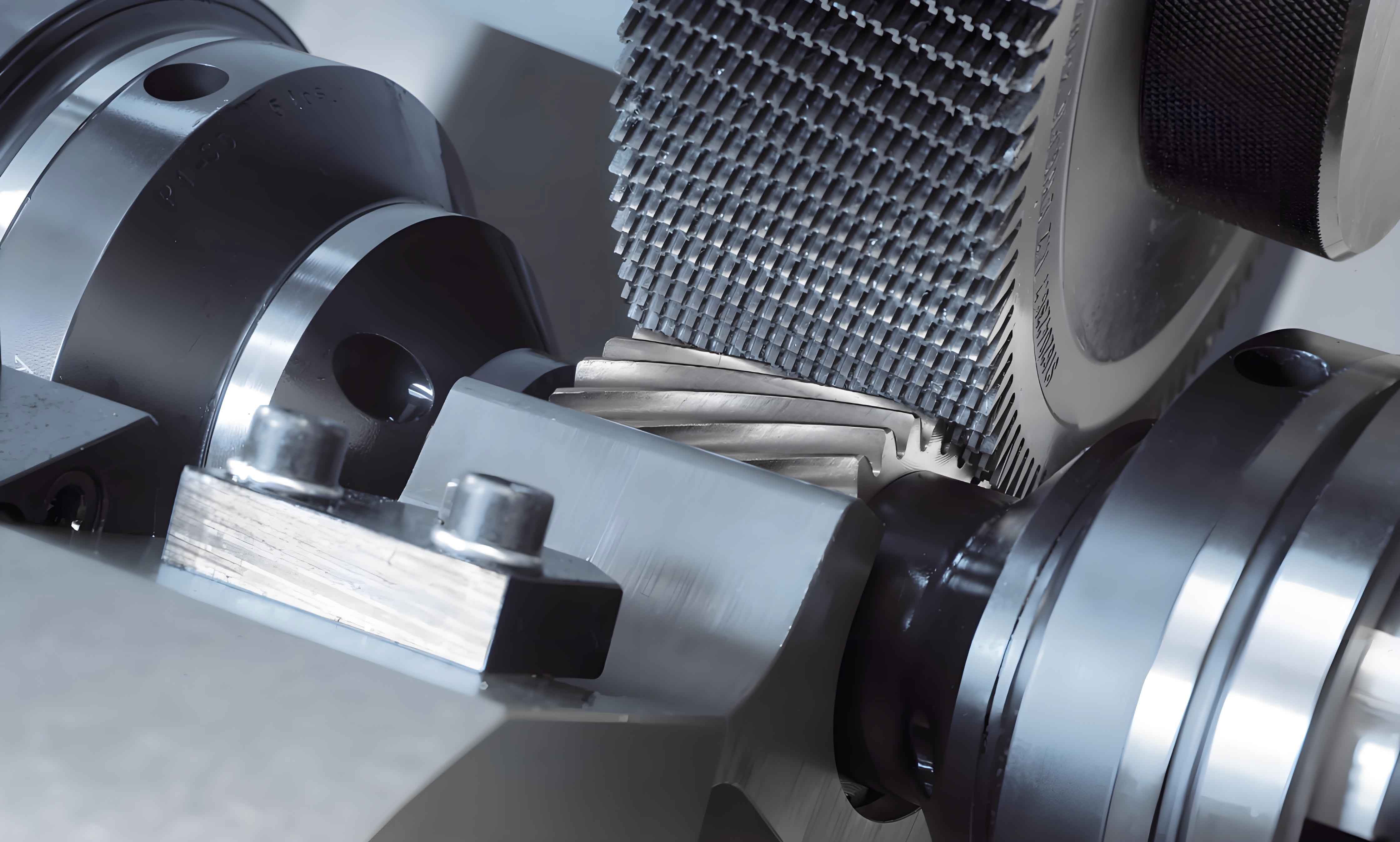
The shaving cutter, essentially a helical gear with numerous small gashes machined across its tooth faces, acts as the cutting tool. When meshed with the workpiece gear at a specific crossed-axes angle (Σ), the rotation of the cutter drives the free-turning workpiece. The critical action is the relative sliding velocity (v) at the mesh point, which serves as the cutting speed. This velocity is the vector difference of the circumferential velocity components along the tooth traces. For a left-hand helical cutter (cutter spiral angle β₀) and a right-hand helical workpiece (work spiral angle β_w), with the cutter rotational speed n₀ (rpm) and pitch diameter d₀ (mm), the cutting speed v (m/min) at the pitch point is given by:
$$ v = v_{0t} \pm v_{wt} = \frac{\pi d_0 n_0}{1000} \sin \Sigma $$
where Σ = β₀ ± β_w, using the plus sign when helix directions are the same and minus when opposite. The serrated edges of the cutter’s gashes peel off ultra-thin chips, typically 0.005–0.010 mm thick, in a combined cutting and plasticizing (extrusion) action, as the tool’s side rake faces have a zero effective clearance angle against the workpiece flank.
During this crossed-axis mesh, the instantaneous contact is theoretically a point (for conventional axial feed gear shaving) or a line (for modern radial feed gear shaving). This contact zone moves along the path of contact, shearing away material. However, an often-overlooked kinematic aspect of any involute gear mesh is the inherent sliding velocity along the tooth profile’s tangent. In a standard parallel-axis mesh, this tangential sliding velocity is zero at the pitch point and increases towards the tooth addendum and dedendum. This motion is always present in the gear shaving mesh as well, oriented parallel to the involute direction at the contact point.
Our analysis converged on a root cause: flank scoring was not caused by the cutter’s sharp edges themselves but by hardened, adherent chips (built-up edge) welded onto these cutting edges. Under normal conditions, chips are pushed into the cutter gash by the rake face. However, excessive localized heat can cause these ductile, steel chips to pressure-weld to the tool’s cutting edge and flank. Once adhered, these tiny, hardened chip fragments are no longer passively carried away. Instead, they are dragged across the gear flank surface by the involute tangential sliding motion inherent to the gear mesh. This dragging action, vectored with the primary cutting motion, produces fine, shallow scratches aligned at an angle to the tooth trace—exactly matching the observed damage pattern. The scoring is worst at the tooth tips because: 1) The cutting speed (v) is highest at the tooth tip/root engagement zone, maximizing heat generation, and 2) The tool’s dedendum (which cuts the gear’s addendum) often has poorer chip evacuation and coolant access, exacerbating heat accumulation and chip adhesion.
Thus, the core issue was thermal. Any factor increasing cutting heat or promoting chip adhesion could trigger scoring. We theorized the main contributors were: workpiece material hardness, cutter sharpness (wear state), cutting parameters (speed, feed, stock), coolant efficacy, and cutter gash design. We undertook a disciplined, single-variable test series to validate each hypothesis.
The results were illuminating and confirmed our thermal-adhesion theory. The effect of material hardness was clear, as shown in Table 1.
| Gear Material | Workpiece Hardness (HBW) | Parts Processed Before Scoring Onset |
|---|---|---|
| FAS3420H | 150 – 161 | 1652 |
| FAS3420H | 165 – 172 | 2056 |
| FAS3420H | 190 – 199 | 1985 |
Excessively soft material led to quicker material adhesion, while overly hard material accelerated tool dulling, both increasing heat. A severely worn cutter caused immediate scoring, while a freshly sharpened one did not. Cutting parameters had a direct impact, summarized in Table 2.
| Cutting Speed (rpm) | Cycle Count* | Shaving Stock (mm) | Scoring Severity |
|---|---|---|---|
| 180 | 5 | 0.15 | Minor |
| 180 | 3 | 0.15 | Severe |
| 240 | 5 | 0.15 | Severe |
| 240 | 5 | 0.10 | Minor |
| 100 | 5 | 0.08 | None |
*Fewer cycles often mean larger infeed per cycle, increasing undeformed chip thickness.
Higher speeds and larger effective depths of cut (from fewer cycles or more stock) increased heat and scoring risk. Most critically, the role of cutting fluid was definitive, as seen in Table 3.
| Coolant Condition | Result |
| Aged (>2 months) | Minor scoring appeared |
| Contaminated (with hydraulic oil) | Severe scoring occurred immediately |
| Fresh, without specialized additives | Scoring began after ~1500 parts |
| Fresh, with lubricity & anti-foam additives | Scoring onset delayed beyond ~2300 parts |
Degraded or contaminated fluid, poor lubricity, and foaming drastically reduced cooling/lubrication performance, leading directly to chip adhesion and scoring.
The validation was complete. Flank scoring in gear shaving was a multi-factorial thermal-adhesion issue. Therefore, the solution required a holistic, system-wide approach. We implemented a comprehensive set of countermeasures.
1. Material Specification: We tightened the incoming material hardness specification to a optimal window of 170-197 HBW, ensuring consistent chip formation without excessive softness (adhesion) or hardness (rapid tool wear).
2. Cutting Fluid Management: We instituted strict coolant maintenance: regular monitoring of concentration and pH, scheduled sump cleaning to prevent tramp oil contamination, and the mandatory use of high-performance additives to enhance extreme pressure lubricity and suppress foam. This was arguably the most impactful single change.
3. Stock Allowance & Pre-Shave Quality: We minimized the total gear shaving stock to the theoretical lower limit, typically 0.06–0.10 mm for sub-module 10 gears, determined by the sum of pre-shave gear tolerances (profile, lead, pitch) and required modification depth. This required closer control of the prior hobbing or shaping process. Reduced stock directly lowers cutting forces and heat generation.
4. Optimized Cutting Parameters: We sacrificed some raw cycle time for process stability. We reduced spindle speeds and adopted multi-pass finishing cycles with lighter radial infeeds to manage heat, especially during the initial roughing phase of the gear shaving cycle.
5. Tooling Strategy: We enforced a proactive tool-life management system based on part count and periodic flank condition inspection, preventing the use of excessively dulled tools. We also collaborated with tooling suppliers to optimize gash geometry for improved chip curling and evacuation.
6. Process Modernization: Shift to Radial Gear Shaving: This was a pivotal strategic change. We transitioned from conventional axial gear shaving to radial (or plunge) gear shaving. The radial gear shaving cutter has a modified tooth form that creates a line contact across the face width. The infeed is purely radial, with no axial stroke. This offers profound advantages: the effective uncut chip thickness is drastically smaller, distributed over a larger contact area, leading to significantly lower localized temperatures. Furthermore, radial gear shaving is faster and provides superior tool life. By resolving the core heat-generation矛盾 (contradiction) between productivity, tool life, and surface quality, radial gear shaving became the ultimate solution to our scoring problem.
The results have been exceptional and sustained. For over a year and across several million production parts, flank scoring has been virtually eliminated. The visual improvement was dramatic—the previously scored, hazy surfaces were replaced by consistent, reflective, and smooth flanks. This directly translated to measurable reductions in gearbox noise levels and enhanced product reliability. Our experience underscores that solving a complex manufacturing defect like flank scoring in gear shaving requires moving beyond symptomatic fixes. It demands a fundamental understanding of the process kinematics and thermal dynamics, rigorous validation of contributing factors, and the implementation of a synchronized, multi-pronged solution that addresses the root cause from every angle.