
In my years of experience in precision gear manufacturing, gear shaving has proven to be a critical finishing process that enhances the accuracy and surface quality of gears. Gear shaving, particularly axial gear shaving, is widely used in industries such as automotive and aerospace to achieve tight tolerances. This article delves into the principles of gear shaving, the mechanics of shaving machines, and a simplified approach to adjusting key parameters like taper, crown, and angle. By sharing my insights, I aim to provide a practical guide that streamlines the adjustment process, reducing setup times and improving efficiency in production environments. Throughout this discussion, I will emphasize the importance of gear shaving and repeatedly highlight the term “gear shaving” to underscore its relevance.
Gear shaving is a finishing operation where a gear-shaped cutter, known as a shaving cutter, meshes with the workpiece gear under crossed axes. The process involves both rolling and sliding actions, which remove minute amounts of material from the gear teeth. In axial gear shaving, the cutter and workpiece are set at an axis intersection angle, typically ranging from 10° to 20°, to generate the necessary sliding motion for cutting. The primary goal of gear shaving is to correct errors from previous machining steps, such as hobbing or shaping, and to produce gears with improved tooth profile, lead, and surface finish. The efficiency of gear shaving hinges on precise adjustments, which I will explore in detail.
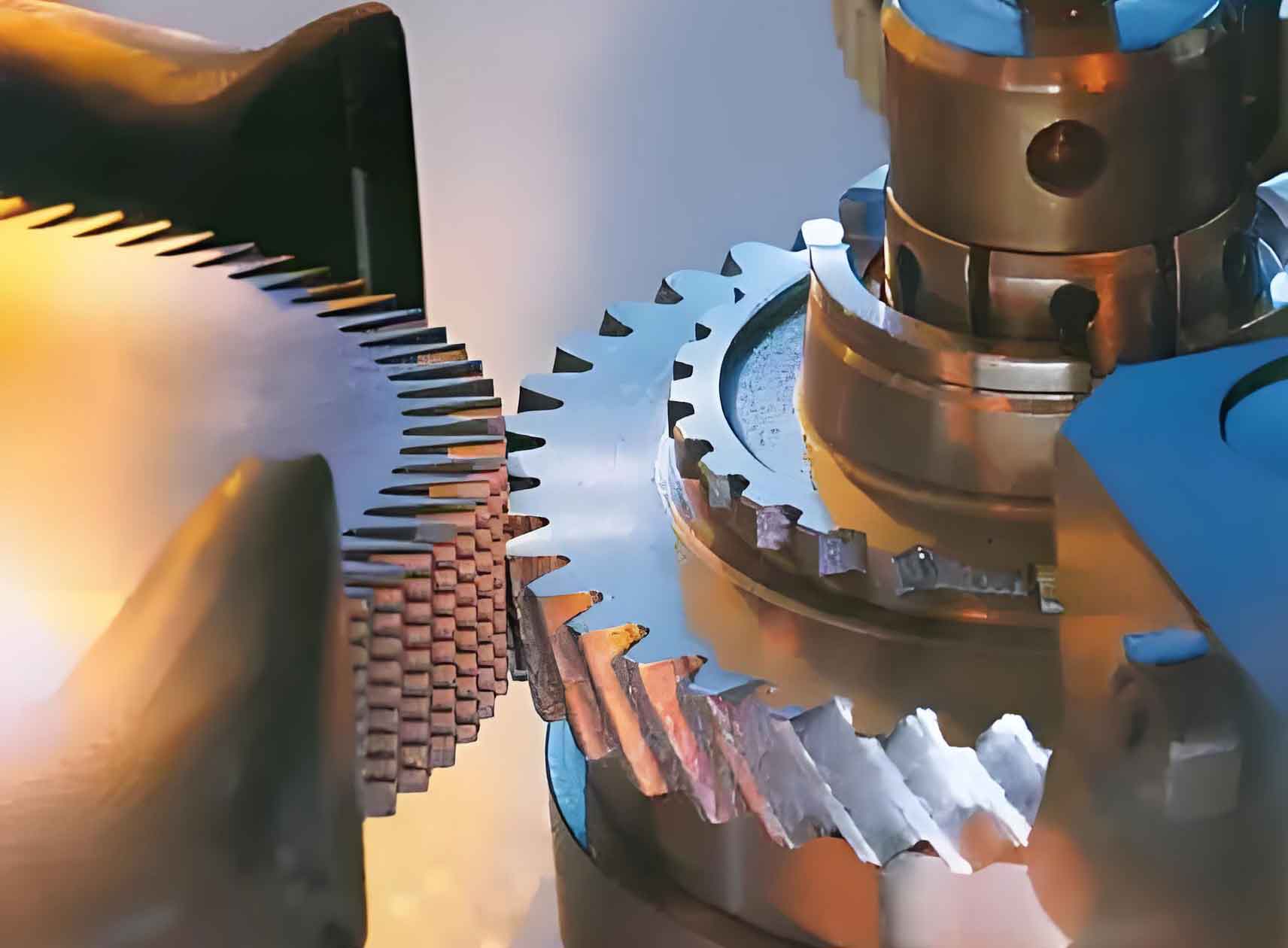
The mechanism behind gear shaving relies on the relative motion between the shaving cutter and the workpiece. As the cutter rotates, it drives the workpiece in a free-rolling mesh, but due to the crossed axes, tangential sliding occurs at the tooth contact points. This sliding action, combined with light radial pressure, results in a shearing effect that trims the gear teeth. The process can be modeled using kinematic equations. For instance, the sliding velocity \( v_s \) at the meshing point can be expressed as:
$$ v_s = v_c \cdot \sin(\Sigma) $$
where \( v_c \) is the peripheral velocity of the cutter and \( \Sigma \) is the axis intersection angle. This equation highlights how gear shaving effectiveness depends on the setup angle. In practice, gear shaving machines are equipped with multiple axes to control this motion. Common axes include:
- Z-axis: Vertical movement for the cutter slide, controlling axial feed.
- X-axis: Horizontal movement for the worktable, enabling transverse adjustments.
- A-axis: Rotational adjustment of the cutter head to set the axis angle.
- B-axis: Spindle rotation for the cutter.
These axes allow for fine-tuning during gear shaving operations. To achieve crowned teeth—where the tooth profile is slightly convex along the face width—a crowning mechanism is integrated into the shaving machine. This mechanism typically uses a four-bar linkage system, as illustrated in the image above. When the sliding block moves horizontally, it induces a tilt in the worktable, creating a variation in center distance across the gear width. This results in a crown shape, with the tooth thickest at the center and tapering toward the ends. The crowning amount is adjusted by changing the angle of a guide rail, denoted as \( \alpha \). When \( \alpha = 0^\circ \), no crowning is produced, emphasizing the versatility of gear shaving for different gear designs.
Adjusting a gear shaving machine is crucial for achieving desired gear specifications. Based on inspection reports from finished gears, operators must modify taper, crown, and angle settings. While machine manuals provide complex formulas, I have developed simplified calculations that are easier to apply on the shop floor. These adjustments are vital for optimizing gear shaving outcomes. Let’s break them down using tables and formulas.
First, taper adjustment compensates for helical errors in gear teeth, ensuring uniform tooth thickness along the face width. The standard formula for taper adjustment \( H \) in millimeters is:
$$ H = \frac{545 \Delta S}{B \sin \alpha} $$
where \( \Delta S \) is the taper deviation in millimeters, \( B \) is the face width in millimeters, and \( \alpha \) is the pressure angle in degrees. However, this can be simplified by using the helix slope deviations from inspection reports. If \( f_{Hb,\text{left}} \) and \( f_{Hb,\text{right}} \) are the left and right flank helix slope deviations in millimeters (with positive or negative signs), the simplified formula is:
$$ H = \left( \frac{f_{Hb,\text{left}} + f_{Hb,\text{right}}}{2} \right) \times 80 $$
The sign of \( H \) indicates the direction for adjustment—positive for one direction and negative for the opposite. This simplification accelerates the gear shaving setup process.
Second, crown adjustment controls the convexity of the tooth along its length. The standard formula for the crowning angle \( \gamma \) in degrees is:
$$ \tan \gamma = \frac{2150 \Delta S}{B^2 \tan \alpha} $$
where \( \Delta S \) is the required crowning amount in millimeters. For common gear parameters, I recommend using pre-calculated tables to avoid complex math. For example, with \( B = 30 \, \text{mm} \) and \( \alpha = 20^\circ \), the formula reduces to:
$$ \tan \gamma = 6.5 \Delta S $$
This allows quick lookup: for \( \Delta S = 0.01 \, \text{mm} \), \( \gamma \approx 3.7^\circ \); for \( \Delta S = 0.02 \, \text{mm} \), \( \gamma \approx 7.4^\circ \). Such tables enhance efficiency in gear shaving operations.
Third, angle adjustment corrects misalignments in tooth orientation. The standard formula for the cutter head rotation \( A \) in degrees is:
$$ A = \tan^{-1} \left( \frac{F}{B} \right) $$
where \( F \) is the lead error over the face width in millimeters. Simplified versions exist for specific shaving machines. For instance, on Y4232CNC models, the adjustment \( P \) in micrometers is:
$$ P = \left( \frac{f_{Hb,\text{left}} – f_{Hb,\text{right}}}{2} \right) \times 14 $$
On YK4232 models, it is:
$$ P = \left( \frac{f_{Hb,\text{left}} – f_{Hb,\text{right}}}{2} \right) \times 10 $$
Again, signs matter for direction. These simplifications are integral to streamlining gear shaving adjustments.
To illustrate, consider a gear shaving example on a YK4232 machine. Suppose the inspection report shows average helix slope deviations of \( f_{Hb,\text{left}} = -6.9 \, \mu\text{m} \) and \( f_{Hb,\text{right}} = 13.2 \, \mu\text{m} \). Using the simplified formulas:
– For taper: \( H = \left( \frac{-6.9 + 13.2}{2} \right) \times 80 = 252 \, \mu\text{m} \). The positive value indicates a specific adjustment direction.
– For angle: \( P = \left( \frac{-6.9 – 13.2}{2} \right) \times 10 = -100 \, \mu\text{m} \). The negative sign guides the swing direction.
This example demonstrates how gear shaving adjustments can be made swiftly without delving into complex trigonometry.
To further aid in gear shaving, I have compiled tables summarizing key parameters. Table 1 lists common pressure angles and their impact on adjustment factors for gear shaving. Table 2 provides crown adjustment angles for typical face widths, emphasizing the role of gear shaving in producing precision gears.
| Pressure Angle \( \alpha \) (degrees) | Taper Factor in Simplified Formula | Crown Factor in \( \tan \gamma \) Calculation |
|---|---|---|
| 14.5 | Higher sensitivity | Requires larger adjustments |
| 20 | Standard reference | Common in automotive gears |
| 25 | Lower sensitivity | Reduces crowning needs |
| Crowning Amount \( \Delta S \) (mm) | Calculated \( \tan \gamma \) | Approximate \( \gamma \) (degrees) |
|---|---|---|
| 0.005 | 0.0325 | 1.86 |
| 0.01 | 0.065 | 3.72 |
| 0.02 | 0.13 | 7.41 |
| 0.03 | 0.195 | 11.04 |
In gear shaving, understanding the machine’s kinematics is essential. The relationship between the sliding block movement and worktable tilt can be expressed with geometry. If the sliding block moves a distance \( x \), the induced tilt angle \( \beta \) and center distance change \( \Delta Z \) are:
$$ \beta = \arctan \left( \frac{x \cdot \sin \alpha}{L} \right) $$
$$ \Delta Z = L \cdot (1 – \cos \beta) $$
where \( L \) is the linkage length. These equations underscore the precision required in gear shaving setups. Moreover, the axial feed rate during gear shaving, denoted as \( f_a \), affects surface finish and is given by:
$$ f_a = \frac{v_z}{n_w} $$
where \( v_z \) is the Z-axis feed velocity and \( n_w \) is the workpiece rotational speed. Optimizing this rate is key to efficient gear shaving.
The benefits of using simplified adjustment methods in gear shaving are manifold. They reduce the number of trial cuts and inspection cycles during changeovers, saving time and material. In my practice, implementing these methods has cut setup times by up to 30%, enhancing overall productivity. Gear shaving, when adjusted correctly, yields gears with tooth profile errors less than 0.005 mm and lead errors under 0.01 mm. The process also improves surface roughness to Ra 0.4 μm or better, which is critical for noise reduction and longevity in gear systems. By focusing on gear shaving adjustments, manufacturers can achieve consistent quality across batches.
Another aspect of gear shaving is tool wear management. The shaving cutter’s life depends on factors like material hardness and cutting parameters. A wear model can be approximated as:
$$ W = k \cdot N^{0.8} $$
where \( W \) is wear in micrometers, \( k \) is a material constant, and \( N \) is the number of gears shaved. Regular monitoring ensures that gear shaving remains effective. Additionally, coolant selection plays a role in gear shaving performance; I recommend using high-lubricity fluids to minimize heat and extend tool life.
In conclusion, gear shaving is a vital finishing process that demands precise adjustments. The simplified methods I’ve shared for taper, crown, and angle adjustments—rooted in practical experience—offer a user-friendly alternative to complex formulas. By incorporating tables and formulas, operators can quickly adapt shaving machines to different gear specifications. Gear shaving, when optimized, significantly enhances gear quality and production efficiency. As industries advance, embracing such streamlined approaches will be crucial for maintaining competitiveness in precision manufacturing. I encourage practitioners to integrate these techniques into their gear shaving routines, continually refining them based on real-world feedback. The future of gear shaving lies in smart adjustments and automation, but for now, these simplifications provide a solid foundation.
To further explore gear shaving, consider the interplay between machine dynamics and gear geometry. For instance, the effective cutting speed in gear shaving, \( v_e \), combines rotational and sliding components:
$$ v_e = \sqrt{v_c^2 + v_s^2} $$
This influences chip formation and surface integrity. Moreover, statistical process control (SPC) can be applied to gear shaving by monitoring adjustment parameters over time, ensuring stability. In my view, ongoing training in gear shaving principles is essential for technicians to leverage these methods fully. By prioritizing gear shaving excellence, manufacturers can deliver superior gears that meet evolving industry standards.