
In the pursuit of higher speed and power transmission characteristics for heavy machinery, the demand for improved manufacturing precision of gears has become paramount. My work focuses on advancing the finishing processes for large-module gears (modules ranging from 8 mm to 16 mm), specifically through the refinement of the gear shaving process. The technical challenges of gear shaving for such components are significant, stemming from the considerable size and weight of the blanks, their elevated hardness, and the structural demands placed on the shaving cutter itself.
Conventional gear shaving of medium-module gears typically involves a relatively soft workpiece which is subsequently heat-treated. This often introduces distortions, profile deviations, and necessitates secondary operations like lapping. For large-module gears, this post-heat-treatment correction is highly undesirable. Therefore, my approach utilizes high-hardness blanks (typically hardened to 40-45 HRC) prior to gear shaving. This allows the process to deliver the final required accuracy and surface finish, eliminating the need for subsequent distortion-prone thermal operations.
The core kinematic principle of gear shaving involves the crossed-axis meshing of the rotary shaving cutter and the gear workpiece. The axis crossing angle, denoted as $\Sigma$, is critical as it generates the relative sliding velocity necessary for the cutting action. For a helical gear, this sliding velocity $v_s$ at the pitch point can be expressed as a function of the rotational speeds and the helix angles. The fundamental relationship governing the generation of the cutting motion is derived from the crossed-axes gear kinematics. The velocity component responsible for the shaving action is given by:
$$ v_s = \omega_c \cdot r_c \cdot \sin(\Sigma) + \omega_w \cdot r_w \cdot \sin(\Sigma) $$
Where $\omega_c$ and $\omega_w$ are the angular velocities of the cutter and workpiece, and $r_c$ and $r_w$ are their pitch radii. However, for the specific configuration in my study where the workpiece is the primary driver, a more practical form focusing on the surface speed is used. The effective cutting speed $v_{eff}$ is largely governed by the component of the workpiece’s tangential velocity along the cutter teeth, which is a function of $\Sigma$ and the helix angles ($\beta_c$ for cutter, $\beta_w$ for workpiece): $\Sigma = \beta_w \pm \beta_c$. The sliding velocity for cutting is thus proportional to $v_w \cdot \sin(\Sigma)$, where $v_w$ is the pitch line velocity of the workpiece.
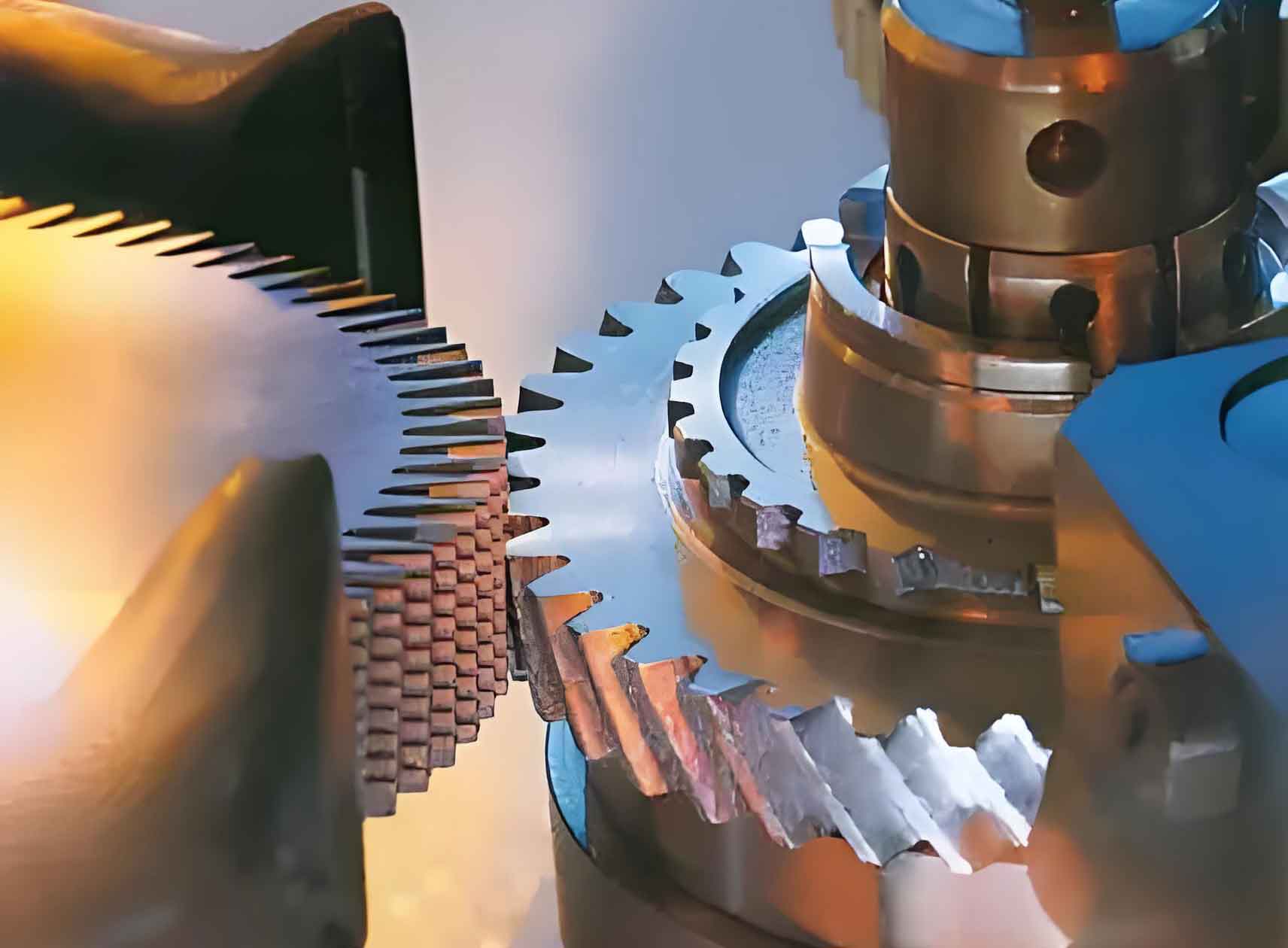
The experimental setup involved mounting the shaving cutter head on a lathe. The workpiece gear was mounted on a mandrel between centers. A significant process modification was implemented concerning the feed reversal. In conventional gear shaving, both the workpiece and cutter rotation reverse direction at the end of each traverse stroke. For large, heavy workpieces, this sudden reversal of a high-inertia mass induces severe vibration, machine instability, and risks chipping the cutter teeth. To mitigate this, I employed a method termed “diagonal feed gear shaving,” where the rotational direction of the cutter remains constant, and only the axial feed direction is reversed. This necessitates the use of a shaving cutter with gashes perpendicular to the tooth trace (rather than the cutter axis) to maintain constant cutting rake angles regardless of feed direction.
The core of my investigation was a comparative analysis between conventional gear shaving and the diagonal feed gear shaving method. The evaluation criterion was the degree of correction, defined as the ratio of the average arithmetic deviation of a gear parameter after gear shaving ($\Delta_{after}$) to its deviation before gear shaving ($\Delta_{before}$). A lower ratio indicates greater error correction. The primary gear quality parameters studied were:
- Profile Form Error ($\Delta f_f$)
- Base Pitch Deviation ($\Delta f_{pb}$)
- Cumulative Pitch Error ($\Delta F_p$)
- Runout ($F_r$)
- Helix Deviation ($\Delta F_{\beta}$)
The initial phase compared the two gear shaving methods at different axis crossing angles $\Sigma$ (5°, 10°, 15°). The results, measured by the degree of correction for profile and base pitch errors, are summarized below. The data shows that both methods perform optimally at $\Sigma = 10°$.
| Crossing Angle $\Sigma$ | Conventional Shaving (Correction Ratio) | Diagonal Feed Shaving (Correction Ratio) |
|---|---|---|
| 5° | 0.55 | 0.52 |
| 10° | 0.42 | 0.40 |
| 15° | 0.60 | 0.58 |
| Crossing Angle $\Sigma$ | Conventional Shaving (Correction Ratio) | Diagonal Feed Shaving (Correction Ratio) |
|---|---|---|
| 5° | 0.48 | 0.46 |
| 10° | 0.35 | 0.33 |
| 15° | 0.50 | 0.49 |
The conclusion from this phase was clear: the diagonal feed gear shaving method is entirely viable for large-module gears, producing accuracy equivalent to the conventional method. The optimal crossing angle for gear shaving high-hardness gears was identified as $\Sigma = 10°$.
Subsequent research phases focused on optimizing process parameters around $\Sigma = 10°$. A key parameter is the stock allowance per tooth flank. My experiments measured the degree of correction achieved with different allowances. The relationship is non-linear; increasing allowance improves correction only up to a point.
| Stock Allowance (mm) | Profile Error Correction Ratio | Base Pitch Error Correction Ratio | Cumulative Pitch Error Correction Ratio |
|---|---|---|---|
| 0.10 | 0.65 | 0.60 | 0.85 |
| 0.15 | 0.45 | 0.40 | 0.70 |
| 0.20 | 0.40 | 0.35 | 0.68 |
| 0.25 | 0.42 | 0.38 | 0.69 |
The data indicates that an allowance of $t = 0.15$ mm provides the best correction for profile and base pitch errors. A smaller allowance ($t < 0.15$ mm) is insufficient to fully eliminate pre-shaving errors in large-module gears. Allowances greater than 0.15 mm do not yield further improvement in geometric accuracy. The optimum can be modeled as a threshold function. We can define an effective correction factor $C_{eff}$ for an error type $E$ as:
$$ C_{eff}(E) = \min\left(1, \,\, k_E \cdot \frac{t}{t_{crit}}\right) \quad \text{for} \,\, t \le t_{crit} $$
$$ C_{eff}(E) = 1 \quad \text{for} \,\, t > t_{crit} $$
Where $t_{crit}$ is the critical stock allowance (approx. 0.15 mm in this case) and $k_E$ is a coefficient specific to the error type (profile, pitch, etc.). The final error after gear shaving $\Delta_{final}$ is then related to the initial error $\Delta_{initial}$ by: $\Delta_{final} = \Delta_{initial} \cdot (1 – C_{eff})$.
The influence of cutting speed (workpiece surface speed at pitch diameter) was also investigated. While its effect on correction degree is less pronounced than that of stock allowance, a clear trend was observed.
| Cutting Speed $v_c$ (m/min) | Profile Error Correction Ratio | Observations |
|---|---|---|
| 20 | 0.45 | Good surface finish, stable process. |
| 40 | 0.48 | Optimum for process efficiency. |
| 60 | 0.55 | Correction degree decreases slightly. |
| >80 | >0.65 | Significant vibration occurs, correction deteriorates. |
At very high speeds ($v_c > 80$ m/min), induced vibration becomes a limiting factor, degrading the gear shaving quality. The optimal speed for efficient and stable gear shaving was found to be approximately $v_c = 40$ m/min. This corresponds to a pitch line velocity that balances cutting action with dynamic stability. The relationship between cutting force $F_c$, speed $v_c$, and vibration $A$ can be heuristically described as increasing non-linearly after a threshold: $A \propto F_c \cdot (v_c – v_{threshold})^2$ for $v_c > v_{threshold}$.
Feed rates were also analyzed. The axial feed per workpiece revolution ($f_a$) showed minimal influence on correction degree within the range of 0.1 to 0.3 mm/rev. The traverse feed per stroke ($f_t$), however, had a significant impact. A moderate traverse feed is essential to generate sufficient radial force for proper cutter engagement without causing excessive load.
| Traverse Feed $f_t$ (mm/stroke) | Radial Force | Correction Degree Trend | Process Condition |
|---|---|---|---|
| < 0.5 | Insufficient | Worsens | Poor cutter guidance, inconsistent contact. |
| 0.5 – 1.0 | Optimal | Best | Stable, full cutter contact maintained. |
| > 1.5 | Excessive | Deteriorates | High load, potential for chatter and edge chipping. |
Based on the comprehensive parameter study, I developed an optimized process window for the gear shaving of high-hardness, large-module gears. The following table summarizes the recommended parameters derived from my experimental analysis.
| Process Parameter | Symbol | Recommended Value / Range | Rationale |
|---|---|---|---|
| Axis Crossing Angle | $\Sigma$ | 10° | Maximizes sliding velocity component for cutting while maintaining good cutter guidance and stability. |
| Stock Allowance (per flank) | $t$ | 0.15 mm | Sufficient to correct pre-shaving errors of large modules without causing excessive force or process time. |
| Cutting Speed (Workpiece) | $v_c$ | 30 – 45 m/min | Balances process efficiency with dynamic stability, avoiding vibration-inducing high speeds. |
| Axial Feed | $f_a$ | 0.1 – 0.3 mm/rev | Has negligible negative impact on accuracy within this range; can be selected based on productivity needs. |
| Traverse Feed per Stroke | $f_t$ | 0.8 – 1.0 mm/stroke | Generates optimal radial force for consistent cutter contact and effective material removal. |
| Finishing Strokes | $n_{fin}$ | 1 – 2 strokes | Additional strokes beyond 2 do not improve geometric accuracy and may reduce surface finish. |
| Shaving Method | – | Diagonal Feed | Eliminates damaging reversals of heavy workpiece inertia, enabling stable processing. |
Implementing this optimized gear shaving strategy resulted in consistent improvement in gear quality. The profile form error and base pitch deviation were typically improved by two ISO accuracy grades. For example, a gear with initial errors corresponding to ISO grade 7 could be reliably finished to grade 5 or better after gear shaving. Cumulative pitch error and runout, which are less influenced by the shearing action of gear shaving, were maintained or slightly improved to grade 6 levels. The helix deviation showed little direct correction from the gear shaving process itself, as it primarily addresses profile and pitch errors; its final quality is largely dependent on the pre-shaving condition.
The success of this gear shaving methodology underscores its viability as a precision finishing operation for high-hardness, large-module gears. The diagonal feed technique successfully addresses the dynamic challenges posed by heavy workpieces. The parameter optimization provides a practical guideline for achieving maximum error correction, transforming a challenging finishing problem into a controlled and reliable process. Future work could involve developing predictive models for tool wear in this high-hardness gear shaving application and investigating the influence of cutter geometry modifications (e.g., profile crowning) applied directly during the shaving process.