
In modern mechanical transmission systems, gears play a pivotal role, and with advancements in manufacturing, the demand for high-quality gear surfaces has increased significantly. Gear modification, particularly for high-speed applications, is essential to achieve high transmission accuracy, strength, and low noise. Among various finishing processes, internal gear honing, or gear honing, stands out due to its efficiency, cost-effectiveness, and ability to produce favorable surface textures that reduce noise. However, traditional gear honing methods often require customized diamond dressing wheels tailored to specific workpiece geometries, which increases costs and development cycles. This limitation hampers the widespread adoption of gear honing for modified gear production. In this study, we propose a novel flexible dressing method for internal gear honing that enables the use of standard diamond dressing wheels to dress the honing wheel, thereby machining modified gears effectively. Our approach focuses on optimizing the multi-axis motions during the dressing process to achieve desired tooth surface modifications, ultimately enhancing the versatility and reducing the expense of gear honing technology.
The internal gear honing process involves two main steps: dressing the honing wheel and honing the workpiece. During dressing, a diamond dressing wheel engages with the internal honing wheel in a meshing motion, supplemented by axial and radial feeds to shape the honing wheel’s tooth surface. In conventional gear honing, the dressing wheel must match the workpiece geometry, necessitating custom tools. Our flexible dressing method overcomes this by introducing controlled multi-axis linkages during dressing, allowing a standard dressing wheel to generate modified honing wheel surfaces. The gear honing machine’s axes, including axial feed (Fz), radial feed (Fx), and rotational axes (C1, C2, A, B), are coordinated via an electronic gearbox structure. By expressing these axis movements as polynomials relative to the axial feed, we can finely tune the dressing process to produce honing wheels that yield modified workpiece tooth surfaces after honing. This method leverages mathematical modeling and sensitivity analysis to optimize the dressing parameters, ensuring that the final gear honing result meets precise modification requirements.
To implement this flexible dressing approach, we first establish mathematical models for both the dressing and honing stages. The coordinate systems for dressing are defined, with transformations linking the diamond dressing wheel, honing wheel, and machine axes. The dressing wheel’s tooth surface is represented as an involute helicoid, parameterized by spiral angle increment θ and involute angle increment λ. Through gear meshing principles, the honing wheel’s tooth surface is derived using coordinate transformations and the meshing equation. The transformation matrices for dressing are given as follows, where Mhs maps the dressing wheel coordinates to the honing wheel coordinates:
$$
M_{h3} = \begin{bmatrix}
\cos \phi_h & \sin \phi_h & 0 & 0 \\
-\sin \phi_h & \cos \phi_h & 0 & 0 \\
0 & 0 & 1 & 0 \\
0 & 0 & 0 & 1
\end{bmatrix}, \quad M_{32} = \begin{bmatrix}
1 & 0 & 0 & 0 \\
0 & \cos \Sigma_A & -\sin \Sigma_A & 0 \\
0 & \sin \Sigma_A & \cos \Sigma_A & 0 \\
0 & 0 & 0 & 1
\end{bmatrix}
$$
$$
M_{20} = \begin{bmatrix}
\cos \Sigma_B & 0 & \sin \Sigma_B & -a_{sh} \\
0 & 1 & 0 & 0 \\
-\sin \Sigma_B & 0 & \cos \Sigma_B & 0 \\
0 & 0 & 0 & 1
\end{bmatrix}, \quad M_{01} = \begin{bmatrix}
1 & 0 & 0 & 0 \\
0 & 1 & 0 & 0 \\
0 & 0 & 1 & F_z \\
0 & 0 & 0 & 1
\end{bmatrix}, \quad M_{1s} = \begin{bmatrix}
\cos \phi_s & -\sin \phi_s & 0 & 0 \\
\sin \phi_s & \cos \phi_s & 0 & 0 \\
0 & 0 & 1 & 0 \\
0 & 0 & 0 & 1
\end{bmatrix}
$$
The composite transformation is:
$$
M_{hs}(F_z, \phi_s) = M_{h3} \cdot M_{32} \cdot M_{20} \cdot M_{01} \cdot M_{1s}(\phi_s)
$$
The rotational relationship between the dressing wheel and honing wheel during gear honing is:
$$
\phi_h = \frac{z_s}{z_h} \phi_s \pm \frac{\tan \beta_h}{r_{bh}} F_z
$$
where φh and φs are the rotation angles of the honing wheel and dressing wheel, zh and zs are their tooth numbers, ash is the center distance, βh is the helix angle, and rbh is the base radius. The meshing equation for conjugate surfaces is:
$$
\frac{\partial \mathbf{r}_1}{\partial \phi_1} \cdot \mathbf{n} = 0
$$
Using this, the honing wheel tooth surface points and normals are computed as:
$$
\mathbf{r}_h(F_z, \phi_s, \lambda, \theta) = M_{hs}(F_z, \phi_s) \cdot \mathbf{r}_s(\lambda, \theta)
$$
$$
\mathbf{n}_h(F_z, \phi_s, \lambda, \theta) = L_{hs}(F_z, \phi_s) \cdot \mathbf{n}_s(\lambda, \theta)
$$
Here, Lhs is the rotation matrix derived from Mhs. The honing wheel surface is then described by a system of equations involving these vectors and the meshing conditions. For the honing stage, similar coordinate systems are established, with transformations linking the honing wheel and workpiece. The workpiece tooth surface is obtained through analogous derivations, ensuring accurate representation of the gear honing process. The transformation for honing is:
$$
M_{gh}(\phi_h) = M_{g1} \cdot M_{12} \cdot M_{2h}(\phi_h)
$$
where Mg1, M12, and M2h are transformation matrices accounting for workpiece rotation, axis alignment, and honing wheel rotation. The workpiece surface points and normals are:
$$
\mathbf{r}_g(F_z, \phi_h, \phi_s, \lambda, \theta) = M_{gh}(\phi_h) \cdot \mathbf{r}_h(F_z, \phi_s, \lambda, \theta)
$$
$$
\mathbf{n}_g(F_z, \phi_h, \phi_s, \lambda, \theta) = L_{gh}(\phi_h) \cdot \mathbf{n}_h(F_z, \phi_s, \lambda, \theta)
$$
This mathematical framework allows us to simulate the tooth surfaces generated during gear honing, providing a basis for optimization.
To achieve flexible dressing, we express the machine axes movements during dressing as polynomials in terms of the axial feed Fz. The center distance ash, axis angles ΣA and ΣB, and dressing wheel rotation φs are parameterized as follows:
$$
a_{sh}(F_z) = a_{sh} + \sum_{k=0}^{4} a_k F_z^k, \quad \Sigma_A(F_z) = \Sigma_A + \sum_{k=0}^{4} A_k F_z^k, \quad \Sigma_B(F_z) = \sum_{k=0}^{4} B_k F_z^k
$$
The dressing wheel rotation is expanded as a Taylor series relative to Fz and φh:
$$
\phi_s(F_z, \phi_h) = c_0 + c_1 F_z + c_2 \phi_h + c_3 F_z^2 + c_4 F_z \phi_h + c_5 \phi_h^2
$$
These polynomials introduce 21 coefficients (a0 to a4, A0 to A4, B0 to B4, c0 to c5), denoted as λ1 to λ21, which serve as design parameters. To optimize these parameters for a target modified tooth surface, we define a sensitivity matrix that quantifies the influence of each coefficient on the final workpiece tooth surface deviations. The tooth surface is discretized into a grid of points—9 points along the profile and 5 points along the width, totaling 45 points per flank. The deviation between the achieved and target surfaces is evaluated as the sum of squared normal errors:
$$
f(\epsilon) = \sum_{i=1}^{45} (\Delta \mathbf{r}_i \cdot \mathbf{n}_i)^2
$$
where Δri is the coordinate difference and ni is the normal vector at point i. The sensitivity matrix A is constructed by computing the partial derivatives of each point’s normal deviation with respect to each design parameter, considering small changes (e.g., 0.001 mm or 0.001°):
$$
\{ \delta \epsilon_i \} = A \{ \delta \lambda_j \} = \left[ \frac{\partial \epsilon_i}{\partial \lambda_j} \right] \{ \delta \lambda_j \}
$$
for i = 1 to 45 and j = 1 to 21. This matrix is often ill-conditioned, so we use singular value decomposition (SVD) to compute its pseudo-inverse for optimization. An iterative algorithm, akin to Newton’s method, is employed to adjust the coefficients until f(ε) is minimized, thereby aligning the gear honing output with the target modification. The optimization flowchart involves initializing parameters, computing the sensitivity matrix, updating coefficients via the pseudo-inverse, and iterating until convergence. This process ensures that the flexible dressing method can effectively produce honing wheels for modified gear honing.
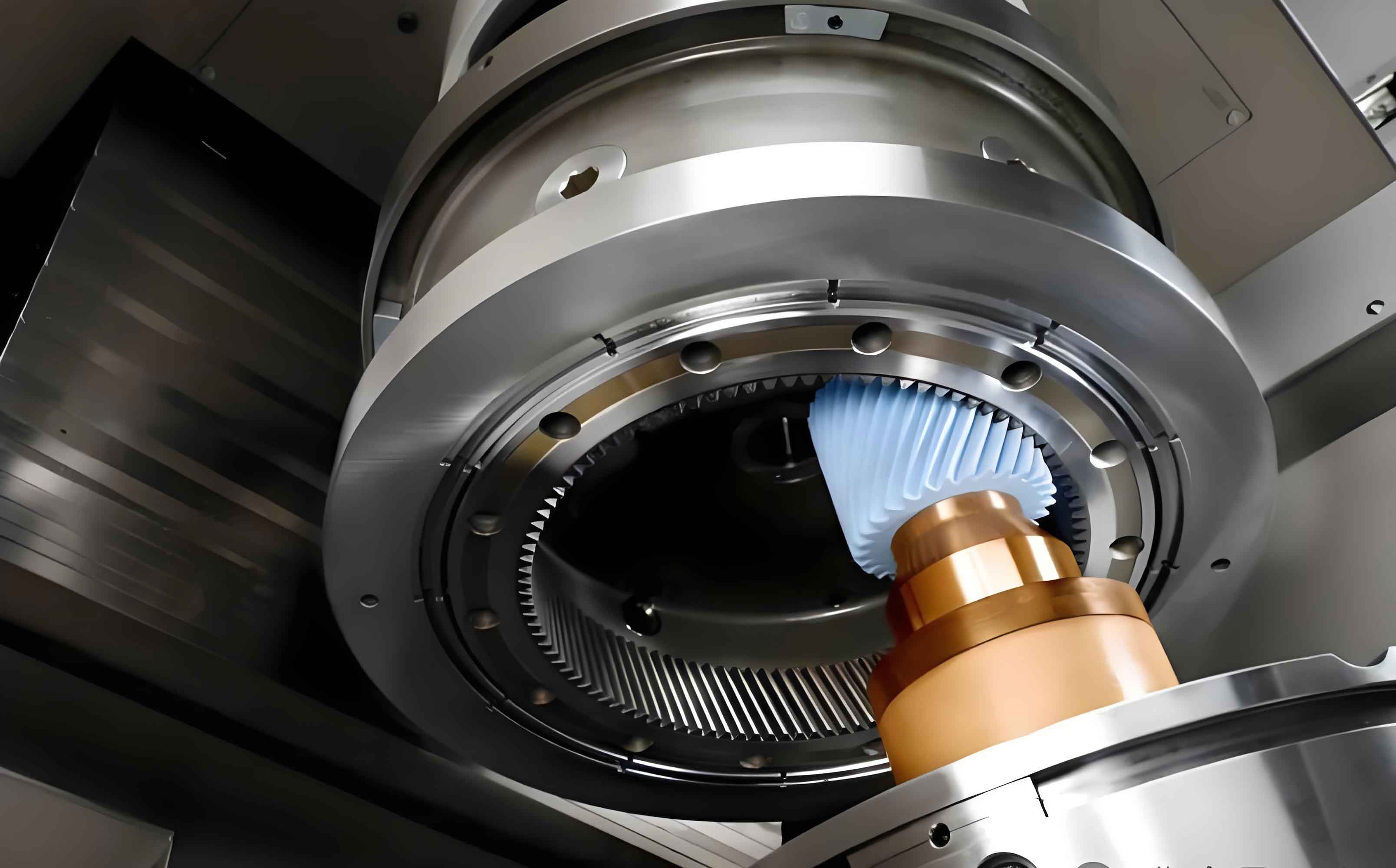
To validate our flexible dressing method for gear honing, we conduct a numerical simulation based on a single-stage gear pair. The gear parameters are listed in the table below, representing a typical high-speed transmission scenario. The driving gear is subjected to modification to improve performance under misalignment conditions, such as 50 μm parallel offset and 20 μm angular misalignment. Using KISSsoft software, we design a target modified tooth surface with profile crowning of 8 μm and lead crowning of 20 μm, optimized to minimize load distribution factor KHβ and maximum contact stress σHmax. This target surface serves as the goal for our gear honing process.
| Parameter | Driving Gear | Driven Gear |
|---|---|---|
| Number of teeth (z1/z2) | 29 | 83 |
| Helix angle β (°) | 22 left-hand | 22 right-hand |
| Normal module mn (mm) | 1.65 | 1.65 |
| Normal pressure angle αn (°) | 19 | 19 |
| Face width b (mm) | 24 | 24 |
We discretize the tooth surface into 45 points and compute the sensitivity matrix A by perturbing each design parameter by 0.001 units. The matrix encapsulates the effects of axis movements on the final gear honing outcome. Through iterative optimization, we obtain the optimal polynomial coefficients, as shown in the following table. These coefficients define the required multi-axis linkages during dressing to achieve the target modification via gear honing.
| Coefficient | Value | Coefficient | Value |
|---|---|---|---|
| a0 | -0.003 | A0 | 0.0393 |
| a1 | 0.0027 | A1 | -0.0002 |
| a2 | 0.0001 | A2 | 0 |
| a3 | 0 | A3 | 0 |
| a4 | 0 | A4 | 0 |
| B0 | 0.0434 | c0 | 0.0152 |
| B1 | -0.0006 | c1 | 0.004 |
| B2 | -0.0003 | c2 | 0.001 |
| B3 | 0 | c3 | 0.0009 |
| B4 | 0 | c4 | 0 |
| c5 | 0 |
Using these coefficients, we calculate the workpiece tooth surface generated by gear honing and compare it to the target surface. The deviation matrix ΣΔ shows normal errors at each discretized point, with values typically within microns, indicating close agreement. For instance, a sample of the deviation matrix is:
$$
\Sigma\Delta = \begin{bmatrix}
0.0261 & 0.0161 & \cdots & 0.0034 & \cdots & 0.0169 & 0.0272 \\
\vdots & \vdots & \ddots & \vdots & \ddots & \vdots & \vdots \\
0.0280 & 0.0181 & \cdots & 0.0056 & \cdots & 0.0190 & 0.0292 \\
0.0291 & 0.0188 & \cdots & 0.0054 & \cdots & 0.0178 & 0.0277 \\
\vdots & \vdots & \ddots & \vdots & \ddots & \vdots & \vdots \\
0.0272 & 0.0170 & \cdots & 0.0035 & \cdots & 0.0162 & 0.0262
\end{bmatrix} \text{ (units in mm)}
$$
The modification effects on both left and right flanks are visualized, demonstrating successful crowning achieved through gear honing. To further assess performance, we perform tooth contact analysis (TCA) in KISSsoft for three scenarios: the standard unmodified tooth surface, the target modified surface, and the surface achieved via our flexible dressing gear honing method. The analysis parameters are set as follows: friction coefficient μ = 0.05, alternating bending factor YM = 1.0, service life = 200,000 hours, application factor KA = 1.25, load distribution factors KHα = 1.0 and KHβ = 1.04, and dynamic factor KV = 1.03. The results show significant improvements for the modified surfaces. The standard surface exhibits a maximum normal force of 1781.54 N/mm and maximum contact stress of 2739.84 N/mm². In contrast, the target modified surface reduces these to 969.61 N/mm and 2223.12 N/mm², respectively. Our gear honing-produced surface yields values of 1010.34 N/mm and 2231.81 N/mm², closely matching the target. This confirms that the flexible dressing method effectively enables gear honing to produce modified gears with enhanced contact characteristics, comparable to ideal designs.
The tooth contact patterns and stress distributions further validate the method. The standard surface shows edge-loading tendencies, while the modified surfaces exhibit more centralized contact, reducing stress concentrations. This alignment demonstrates that gear honing with flexible dressing can achieve desired modifications without custom dressing wheels. The process’s robustness is underscored by the iterative optimization, which efficiently handles the multi-parameter space via sensitivity analysis. Moreover, the use of standard diamond dressing wheels lowers costs and increases flexibility, making gear honing more accessible for custom gear production. Our mathematical models ensure precision, and the polynomial representation of axis motions allows for fine-tuning across diverse modification requirements. In practice, this method can be integrated into CNC gear honing machines with electronic gearbox capabilities, enabling real-time adjustments during dressing for different workpiece specifications.
In conclusion, we have developed and validated a flexible dressing method for internal gear honing that addresses the limitations of traditional approaches. By expressing machine axis movements as polynomials and optimizing coefficients via sensitivity matrix analysis, we enable the use of standard diamond dressing wheels to dress honing wheels for modified gear production. The mathematical models for dressing and honing provide a rigorous foundation, and numerical simulations confirm that the method achieves tooth surface modifications closely aligning with target designs. Tooth contact analysis reveals significant improvements in load distribution and stress reduction, comparable to ideal modified surfaces. This advancement enhances the versatility and cost-effectiveness of gear honing technology, paving the way for broader adoption in high-precision gear manufacturing. Future work may explore real-time adaptive control during gear honing, extension to more complex modifications, and experimental validation on physical gear honing machines to further refine the process.