
In modern industrial applications, the demand for high-performance gears with enhanced strength, stability, and noise reduction is continuously increasing. Gear honing, a precision finishing process, plays a crucial role in achieving these qualities by improving surface integrity and correcting errors from previous manufacturing steps. However, traditional gear honing methods often rely on dedicated diamond dressing tools to modify the honing wheel, leading to high costs and limited flexibility for different gear profile parameters. To address these challenges, this paper proposes a novel topology modification method for CNC internal gear power honing, which adjusts the motion parameters of machine tool axes to achieve comprehensive tooth surface correction without requiring specialized dressing tools. By leveraging advanced mathematical modeling and optimization techniques, this approach enhances the versatility of diamond dressing wheels, reduces processing costs, and shortens gear development cycles, thereby advancing the capabilities of gear honing in precision manufacturing.
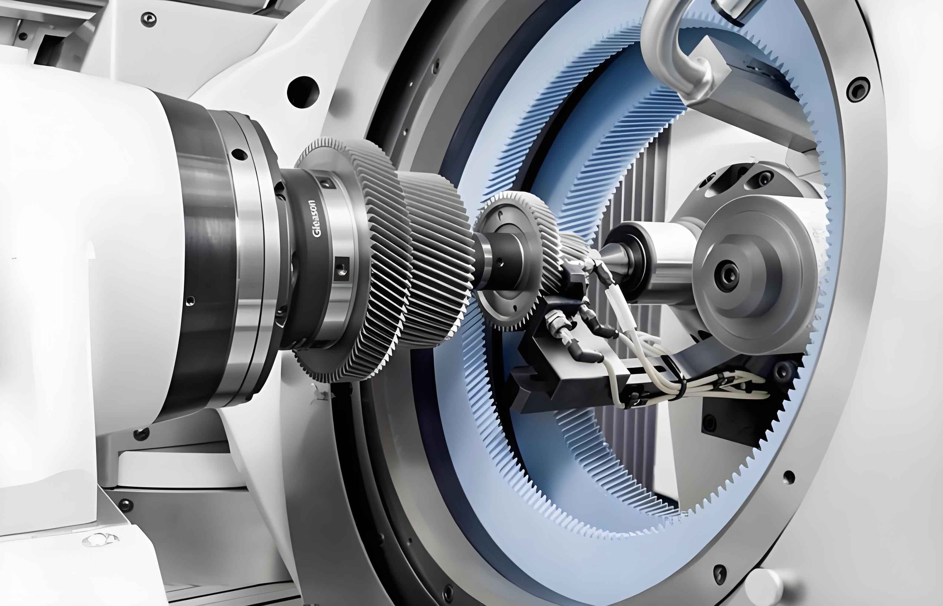
The internal gear power honing process involves the meshing of an internal honing wheel (the tool) with an external workpiece gear in a crossed-axis configuration. During gear honing, the abrasive-laden surface of the honing wheel teeth engages with the workpiece gear teeth under electronic gearbox control, removing material through a combination of cutting and polishing actions. This process is particularly effective for finishing hardened gears, as it improves surface finish, reduces noise, and corrects deviations. However, due to the non-conjugate nature of the meshing, interference can occur, necessitating precise modification of the honing wheel. Traditionally, this is done using diamond dressing gears that match the desired workpiece profile, but this limits adaptability. The proposed method overcomes this by dynamically adjusting the motions of the machine tool axes—specifically, the radial feed axis (X), the axial movement axes (Z1 and Z2), the honing wheel rotation axis (C1), the workpiece rotation axis (C2), the crossed-axis angle adjustment axis (A), and the honing wheel oscillation axis (B)—through high-order polynomial functions. This enables topology modification across the entire tooth surface, allowing for tailored corrections in both profile and lead directions.
To understand the foundation of this method, we first establish the mathematical models for the gear surfaces involved in gear honing. The process begins with a standard diamond dressing gear, whose tooth surface is represented as an involute helicoid. In a coordinate system attached to the diamond dressing gear, any point on its surface can be described by position vector and normal vector equations. For instance, the position vector $$ \mathbf{r}_d(\theta_d, \lambda_d) $$ and normal vector $$ \mathbf{n}_d(\theta_d, \lambda_d) $$ are derived from basic gear parameters such as base radius, spiral angle, and incremental angles. These equations form the basis for generating the honing wheel surface through an enveloping process. The honing wheel, in turn, is produced by dressing with the diamond gear on a CNC internal gear honing machine, where relative motions between the axes simulate the meshing action. By applying coordinate transformation matrices that account for rotations and translations, we obtain the honing wheel surface as an envelope of the diamond gear surface. This involves solving the meshing equation $$ f(\theta_d, \lambda_d, \Phi_d) = 0 $$, which ensures contact between the surfaces during dressing. The resulting honing wheel surface, represented as $$ \mathbf{r}_h(\theta_d, \lambda_d, \Phi_d) $$, serves as the tool for subsequent gear honing of the workpiece.
For the workpiece gear honing, a more complex model is required due to the multi-axis motions involved in topology modification. The CNC internal gear honing machine typically includes seven axes: X (radial feed), Z1 and Z2 (axial movements), C1 (honing wheel rotation), C2 (workpiece rotation), A (crossed-axis angle adjustment), and B (honing wheel oscillation). To achieve topology modification, the motions of the A, B, and X axes are expressed as high-order polynomial functions with two variables: the honing wheel rotation angle $$ \Phi_{C1} $$ and the axial displacement $$ L_Z $$. These polynomials allow fine control over the tooth surface generation. For example, the motion of the X axis can be written as:
$$ L_X(\Phi_{C1}, L_Z) = a_0 + a_1 \Phi_{C1} + a_2 L_Z + a_3 \Phi_{C1}^2 + a_4 L_Z^2 + a_5 \Phi_{C1} L_Z $$
Similarly, the A and B axis motions are given by:
$$ \Phi_A(\Phi_{C1}, L_Z) = \Sigma_{wh} + a_6 + a_7 \Phi_{C1} + a_8 L_Z + a_9 \Phi_{C1}^2 + a_{10} L_Z^2 + a_{11} \Phi_{C1} L_Z $$
$$ \Phi_B(\Phi_{C1}, L_Z) = a_{12} + a_{13} \Phi_{C1} + a_{14} L_Z + a_{15} \Phi_{C1}^2 + a_{16} L_Z^2 + a_{17} \Phi_{C1} L_Z $$
Here, $$ \Sigma_{wh} $$ represents the initial crossed-axis angle determined by the spiral angles of the honing wheel and workpiece, and $$ a_i $$ are coefficients to be optimized. The workpiece rotation is synchronized via an electronic gearbox relationship: $$ \Phi_{C2}(\Phi_{C1}, L_Z) = \frac{Z_{1h}}{Z_{1w}} \Phi_{C1} \pm \frac{\tan \beta_w}{r_{pw}} L_Z $$, where $$ Z_{1h} $$ and $$ Z_{1w} $$ are tooth numbers, $$ \beta_w $$ is the workpiece spiral angle, and $$ r_{pw} $$ is the pitch radius. Using these motion functions, the workpiece tooth surface is derived as an envelope of the honing wheel surface through coordinate transformations and meshing equations. The resulting surface $$ \mathbf{r}_w(\theta_d, \lambda_d, \Phi_d, \Phi_{C1}, L_Z) $$ and its normal vector $$ \mathbf{n}_w(\theta_d, \lambda_d, \Phi_d, \Phi_{C1}, L_Z) $$ define the topology-modified gear after honing.
Topology modification in gear honing refers to the deliberate deviation of the tooth surface from a standard involute form to optimize meshing performance, such as reducing stress concentrations or noise. This is achieved by specifying a target modification surface, often represented as a grid of points on the tooth flank. For analysis, the tooth surface is divided into a 5×9 grid (45 points), and the normal deviation at each point is calculated as the difference between the modified and theoretical surfaces. The deviation $$ \delta_i $$ at the i-th grid point is given by:
$$ \delta_i = (\mathbf{r}_{cw_i} – \mathbf{r}_{w_i}) \cdot \mathbf{n}_{w_i} $$
where $$ \mathbf{r}_{cw_i} $$ is the position vector of the modified surface, $$ \mathbf{r}_{w_i} $$ is the theoretical surface, and $$ \mathbf{n}_{w_i} $$ is the normal vector. The goal is to adjust the polynomial coefficients $$ a_i $$ to minimize these deviations, effectively shaping the tooth surface through controlled motions during gear honing. To relate coefficient changes to surface deviations, a sensitivity matrix is constructed by perturbing each coefficient slightly (e.g., by 0.001) and computing the resulting normal deviations across all grid points. This yields a matrix $$ \mathbf{S} $$ of size 45×18, where each element $$ \frac{\partial \delta_i}{\partial a_j} $$ represents the sensitivity of the i-th point to the j-th coefficient. The relationship can be expressed as:
$$ \Delta \boldsymbol{\delta} = \mathbf{S} \Delta \mathbf{a} $$
with $$ \Delta \boldsymbol{\delta} $$ being the vector of deviation changes and $$ \Delta \mathbf{a} $$ the vector of coefficient adjustments. Analyzing this sensitivity matrix reveals the influence of each axis on the tooth surface. For instance, coefficients associated with the B axis (oscillation) typically show higher sensitivity for profile modifications, while the A axis (crossed-angle) affects lead corrections, and the X axis (radial feed) has a lower overall impact but contributes to tooth thickness adjustments. This insight guides the optimization process for achieving desired topology in gear honing.
To solve for the polynomial coefficients that produce a target modification, an optimization problem is formulated. Given the target deviations $$ \delta_i $$ at grid points, we seek coefficients $$ a_i $$ such that the computed deviations match these targets as closely as possible. Since the system is overdetermined (45 equations for 18 unknowns), direct inversion is not feasible. Instead, we employ the Particle Swarm Optimization (PSO) algorithm, a global optimization method known for its efficiency and robustness. The objective function minimizes the sum of squared differences between target and actual deviations, with a constraint to account for material removal during gear honing (i.e., deviations must be negative or zero to indicate cutting rather than interference). The function is defined as:
$$ y = \min \sum_{i=1}^{45} f(i)^2 $$
where
$$ f(i) =
\begin{cases}
-\delta_i – \mathbf{S}_i \mathbf{a}, & \text{if } \mathbf{S}_i \mathbf{a} < 0 \\
-\delta_i, & \text{if } \mathbf{S}_i \mathbf{a} \geq 0
\end{cases} $$
Here, $$ \mathbf{S}_i $$ is the i-th row of the sensitivity matrix, and $$ \mathbf{a} $$ is the vector of coefficients. The PSO algorithm iteratively adjusts coefficient values to reduce this error, converging to an optimal set that defines the axis motions for topology modification in gear honing. This approach allows for precise control without needing physical changes to dressing tools, enhancing the flexibility of the gear honing process.
To validate the method, a simulation case study is conducted using typical gear parameters for honing. The workpiece gear, honing wheel, and diamond dressing gear specifications are summarized in the table below:
| Parameter | Workpiece Gear | Honing Wheel | Diamond Dressing Gear |
|---|---|---|---|
| Number of Teeth | 57 | 151 | 61 |
| Module (mm) | 1.94 | 1.94 | 1.94 |
| Pressure Angle (°) | 18 | 18 | 18 |
| Face Width (mm) | 20 | 24 | 28 |
| Helix Angle (°) | 23.000 | 31.009 | 23.000 |
| Hand of Spiral | Right | Right | Right |
Using these parameters, the sensitivity matrix is computed by perturbing each coefficient $$ a_0 $$ to $$ a_{17} $$ by 0.001 and calculating the normal deviations. The resulting matrix, though large, highlights key trends: for example, coefficients for the B axis have the highest sensitivity values, indicating strong influence on profile modifications, while A axis coefficients affect lead corrections, and X axis coefficients have minor impacts on tooth thickness. This aligns with the physical understanding of gear honing dynamics. Next, a target topology modification is defined, such as a crowned surface with specific deviations across the grid. The PSO algorithm is applied with a population size of 50 and iterations up to 100. The convergence plot shows that the objective function stabilizes after about 80 iterations, yielding optimal coefficients. The table below lists the resulting motion functions for each axis:
| Motion Axis | Theoretical Motion (Standard Honing) | Actual Motion with Topology Modification |
|---|---|---|
| C1 | $$ \Phi_{C1} $$ | $$ \Phi_{C1} $$ |
| Z1 | $$ L_Z $$ | $$ L_Z $$ |
| X | 0 | $$ -0.0014 – 0.0011 \Phi_{C1} + 1.0822 \times 10^{-6} L_Z + 0.0020 \Phi_{C1}^2 + 8.9101 \times 10^{-4} L_Z^2 – 1.4024 \times 10^{-7} \Phi_{C1} L_Z $$ |
| A | $$ 8.0090 $$ | $$ 8.0090 + 5.2844 \times 10^{-5} + 1.2579 \times 10^{-4} \Phi_{C1} – 6.5778 \times 10^{-9} L_Z – 3.9876 \times 10^{-4} \Phi_{C1}^2 – 3.7462 \times 10^{-6} L_Z^2 – 1.9853 \times 10^{-7} \Phi_{C1} L_Z $$ |
| B | 0 | $$ 4.3068 \times 10^{-6} – 5.3102 \times 10^{-5} \Phi_{C1} + 2.9730 \times 10^{-7} L_Z – 1.0146 \times 10^{-5} \Phi_{C1}^2 – 2.2479 \times 10^{-7} L_Z^2 – 3.5704 \times 10^{-10} \Phi_{C1} L_Z $$ |
| C2 | $$ 2.6491 \Phi_{C1} \pm 0.0710 L_Z $$ | $$ 2.6491 \Phi_{C1} \pm 0.0710 L_Z $$ |
With these motions, the simulated tooth surface after gear honing closely matches the target topology. The modification error, calculated as the difference between target and achieved deviations, is within 6 μm across most grid points, with slightly higher errors near the gear edges due to boundary effects. This demonstrates the effectiveness of the method in achieving precise topology modification through controlled axis motions in gear honing. The ability to tailor surfaces without changing dressing tools significantly enhances the adaptability of CNC internal gear honing machines for various applications.
The advantages of this topology modification method in gear honing are multifaceted. First, it eliminates the need for dedicated diamond dressing gears for each modification profile, reducing tooling costs and inventory. Second, it allows rapid prototyping and adjustment of gear designs, shortening development cycles. Third, the use of high-order polynomials provides fine control over surface corrections, enabling complex modifications like crowning, twist, or localized adjustments. Moreover, the integration with PSO optimization ensures robust and automated parameter selection, minimizing human error. In practice, this method can be implemented on existing CNC internal gear honing machines with software updates, making it a cost-effective upgrade. Future work could explore real-time adaptive control based on in-process measurements, further enhancing the precision of gear honing for high-performance applications such as automotive transmissions or aerospace gearboxes.
In conclusion, this paper presents a comprehensive topology modification method for CNC internal gear power honing that leverages mathematical modeling, sensitivity analysis, and optimization algorithms. By expressing axis motions as high-order polynomial functions and optimizing coefficients via PSO, desired tooth surface modifications can be achieved without specialized dressing tools. Simulation results confirm the method’s accuracy and flexibility, with errors below 6 μm. This approach not only improves the versatility of gear honing processes but also contributes to cost reduction and faster gear production. As industries continue to demand higher gear quality, such advanced methods will play a pivotal role in advancing manufacturing capabilities. The ongoing evolution of gear honing technology promises even greater precision and efficiency in the future.
To further elaborate on the mathematical foundations, let’s consider the detailed derivation of the honing wheel surface. Starting from the diamond dressing gear, its tooth surface is defined in a coordinate system $$ S_d $$ with parameters $$ \theta_d $$ (spiral increment) and $$ \lambda_d $$ (involute increment). The position vector is:
$$ \mathbf{r}_d(\theta_d, \lambda_d) = \begin{bmatrix} x_d \\ y_d \\ z_d \end{bmatrix} = \begin{bmatrix} r_{bd} \cos(\sigma_{0d} + \theta_d + \lambda_d) + r_{bd} \lambda_d \sin(\sigma_{0d} + \theta_d + \lambda_d) \\ r_{bd} \sin(\sigma_{0d} + \theta_d + \lambda_d) – r_{bd} \lambda_d \cos(\sigma_{0d} + \theta_d + \lambda_d) \\ \theta_d p_d \end{bmatrix} $$
where $$ r_{bd} $$ is the base radius, $$ \sigma_{0d} $$ is the start angle, and $$ p_d = r_{bd} \tan \beta_{bd} $$ is the lead. The normal vector is obtained from the cross product of partial derivatives:
$$ \mathbf{n}_d(\theta_d, \lambda_d) = \frac{\partial \mathbf{r}_d}{\partial \lambda_d} \times \frac{\partial \mathbf{r}_d}{\partial \theta_d} = \begin{bmatrix} p_d \lambda_d r_{bd} \sin(\sigma_{0d} + \theta_d + \lambda_d) \\ -p_d \lambda_d r_{bd} \cos(\sigma_{0d} + \theta_d + \lambda_d) \\ \lambda_d r_{bd}^2 \end{bmatrix} $$
For the honing wheel generation, coordinate transformations are applied based on machine kinematics. The transformation from $$ S_d $$ to the honing wheel system $$ S_h $$ involves rotations and translations corresponding to axes A, X, C1, and C2. The homogeneous transformation matrix $$ \mathbf{M}_{hd}(\Phi_d) $$ is constructed as:
$$ \mathbf{M}_{hd}(\Phi_d) = \mathbf{M}_{hb}(\Phi_h) \mathbf{M}_{ba}(\Sigma_{hd}) \mathbf{M}_{ad}(\Phi_d) $$
with $$ \Phi_h = \frac{Z_{1d}}{Z_{1h}} \Phi_d $$ representing the gear ratio. The honing wheel surface then satisfies the meshing equation:
$$ f(\theta_d, \lambda_d, \Phi_d) = \mathbf{n}_d \cdot \mathbf{v}_d^{hd} = 0 $$
where $$ \mathbf{v}_d^{hd} $$ is the relative velocity in $$ S_d $$. Solving this yields $$ \Phi_d $$ as a function of $$ \theta_d $$ and $$ \lambda_d $$, and the honing wheel surface is:
$$ \mathbf{r}_h(\theta_d, \lambda_d, \Phi_d) = \mathbf{M}_{hd}(\Phi_d) \mathbf{r}_d(\theta_d, \lambda_d) $$
$$ \mathbf{n}_h(\theta_d, \lambda_d, \Phi_d) = \mathbf{L}_{hd}(\Phi_d) \mathbf{n}_d(\theta_d, \lambda_d) $$
where $$ \mathbf{L}_{hd} $$ is the rotational submatrix of $$ \mathbf{M}_{hd} $$. This surface serves as the tool for workpiece honing.
In workpiece gear honing, additional transformations account for all seven axes. The overall transformation from $$ S_h $$ to the workpiece system $$ S_w $$ is:
$$ \mathbf{M}_{wh}(\Phi_{C1}, L_Z) = \mathbf{M}_{wg}(\Phi_{C2}) \mathbf{M}_{gf}(L_X, L_Z) \mathbf{M}_{fe}(\Phi_B) \mathbf{M}_{ec}(\Phi_A) \mathbf{M}_{ch}(\Phi_{C1}) $$
with $$ \Phi_{C2} $$ defined by the electronic gearbox relationship. The workpiece surface is then the envelope of the honing wheel surface, requiring solutions to two independent meshing equations for parameters $$ \Phi_{C1} $$ and $$ L_Z $$. This results in a system that defines the topology-modified tooth surface after gear honing.
The sensitivity matrix plays a key role in linking coefficient adjustments to surface changes. For computational efficiency, it can be approximated using finite differences. For each coefficient $$ a_j $$, a small perturbation $$ \Delta a_j = 0.001 $$ is applied, and the resulting normal deviations $$ \Delta \delta_i $$ are computed across the grid. This forms column j of the matrix. The sensitivity values depend on gear geometry and machine kinematics, but generally, higher-order terms (e.g., quadratic coefficients) have more localized effects, while linear terms influence broader trends. This matrix is essential for the PSO optimization, as it guides the search direction towards coefficient sets that minimize deviation errors.
The PSO algorithm operates by maintaining a swarm of particles, each representing a candidate solution (vector of coefficients). Particles move through the search space based on their own experience and the swarm’s best-known position. The velocity update equation for particle k is:
$$ \mathbf{v}_k^{t+1} = w \mathbf{v}_k^t + c_1 r_1 (\mathbf{p}_{\text{best},k} – \mathbf{x}_k^t) + c_2 r_2 (\mathbf{g}_{\text{best}} – \mathbf{x}_k^t) $$
where $$ w $$ is inertia weight, $$ c_1 $$ and $$ c_2 $$ are acceleration coefficients, $$ r_1 $$ and $$ r_2 $$ are random numbers, $$ \mathbf{p}_{\text{best},k} $$ is the particle’s best position, and $$ \mathbf{g}_{\text{best}} $$ is the global best position. The position update is $$ \mathbf{x}_k^{t+1} = \mathbf{x}_k^t + \mathbf{v}_k^{t+1} $$. For our problem, the objective function evaluates each particle by computing the tooth surface deviations using the current coefficients and comparing to targets. The PSO parameters used in simulation are: swarm size 50, $$ w = 0.7 $$, $$ c_1 = c_2 = 1.5 $$, and maximum iterations 100. Convergence is typically achieved within 80 iterations, yielding coefficients that produce accurate topology modification in gear honing.
To illustrate the impact of topology modification on gear performance, consider the contact pattern and transmission error. Modified surfaces can reduce edge loading and lower noise by providing a more gradual engagement. In gear honing, this is achieved by tailoring the tooth flank deviations. For example, a crowned surface (high points in the center) compensates for misalignments, while a twisted surface corrects for manufacturing errors. The proposed method allows such modifications through axis motions, as demonstrated in the simulation. The ability to dynamically adjust these motions based on real-time feedback could further enhance gear honing quality, paving the way for smart manufacturing systems.
In summary, this topology modification method for CNC internal gear power honing represents a significant advancement in gear finishing technology. By integrating mathematical modeling, sensitivity analysis, and optimization, it enables precise surface corrections without dedicated tools, enhancing the versatility and efficiency of gear honing processes. As industries strive for higher performance and lower costs, such innovations will be crucial in meeting future demands. The continued development of gear honing techniques, supported by digital tools and automation, promises to drive progress in precision engineering across various sectors.