
In my research, I focus on the gear cutting of small module spiral bevel gears, which are widely used in office equipment, power tools, and mechanical instruments due to their compact size. The demand for higher meshing performance in these applications has driven the need for improved gear cutting methods. Traditionally, the duplex spread-blade method has been employed for gear cutting of these gears, using specialized milling machines. This approach involves cutting both sides of the tooth slot for both the gear and pinion in a single pass, ensuring high production efficiency. However, this gear cutting technique often leads to poor control over the tooth contact pattern, fundamentally limiting the transmission performance. To address this, I investigate the use of Tooth Contact Analysis (TCA) technology to modify and optimize gear cutting parameters, thereby enhancing the contact condition and meshing quality. This allows me to maintain the production efficiency of the duplex spread-blade method while significantly improving gear performance.
The duplex spread-blade method for gear cutting was initially developed by Gleason in the 1940s for small module spiral bevel gears, utilizing machines like the “G4” mill. Later, companies such as Okamoto and domestic manufacturers in China produced similar machines. Despite its efficiency, this gear cutting method was eventually phased out by Gleason in favor of more advanced techniques like the “Duplex Helical” method, which requires more complex machinery. In my work, I revisit the duplex spread-blade method with modern computational tools, aiming to overcome its limitations through precise parameter optimization. This gear cutting approach is particularly economical for small module gears, where cost constraints are critical, and high-volume production is common.
My research begins with a theoretical analysis of the duplex spread-blade gear cutting process. The core idea is to ensure that at the calculation point, both the gear and pinion have identical spiral angles and pressure angles. However, due to the nature of this gear cutting method, only the calculation point meets this condition, leading to deviations elsewhere on the tooth surface. This results in diagonal contact and requires strict control over the cutter specifications. The traditional calculation process involves geometric corrections to the blank, such as adjusting the root angle to compensate for spiral angle deviations. The key formulas used in this gear cutting analysis are as follows.
The tooth line convergence angle is given by:
$$ \phi_o = \frac{S_o}{L} $$
where \( \phi_o \) is the convergence angle, \( S_o \) is the tooth thickness, and \( L \) is the cone distance at the center point. The normal convergence angle of the tooth line is:
$$ \phi_u = \frac{S_o \sin \beta}{r_u} $$
where \( \beta \) is the spiral angle at the midpoint, and \( r_u \) is the nominal cutter radius. The spiral angle deviation \( \Delta \beta \) arises because \( \phi_u \neq \phi_o \), expressed as:
$$ \Delta \beta = \phi_o – \phi_u = \frac{S_o}{L} \left(1 – \frac{L \sin \beta}{r_u}\right) $$
This deviation can be corrected by tilting the root cone angle \( \gamma \), leading to:
$$ \tan \gamma \approx \gamma = \frac{S_o}{2L \tan \alpha \cos \beta} \left(1 – \frac{L}{r_u} \sin \beta\right) $$
where \( \alpha \) is the pressure angle. The sum of the root angles for the gear and pinion is:
$$ \gamma_1 + \gamma_2 = \frac{10,800}{z_c \tan \alpha \cos \beta} \left(1 – \frac{L}{r_u} \sin \beta\right) $$
and the cutter number \( No \) is:
$$ No = \frac{\gamma_1 + \gamma_2}{20 \sin \beta} = \frac{540 \tan \beta}{z_c \tan \alpha} \left(1 – \frac{L}{r_u} \sin \beta\right) $$
For a pressure angle \( \alpha = 20^\circ \), this simplifies to:
$$ No = \frac{1483 \tan \beta}{z_c} \left(1 – \frac{L}{r_u} \sin \beta\right) $$
These formulas are fundamental to the gear cutting parameter calculation in the duplex spread-blade method, but they rely on approximations that can lead to inaccuracies in contact patterns.
To enhance this gear cutting process, I integrate TCA technology. TCA is a numerical simulation tool that models the meshing of gear teeth, allowing for the prediction of contact patterns, transmission error curves, and sensitivity to misalignments. By using TCA, I can iteratively adjust gear cutting parameters such as machine setting angles, cutter specifications, and feed rates to achieve optimal contact conditions. This represents a significant advancement over traditional trial-and-error methods, which depend heavily on operator experience. In my approach, I develop software that automates the calculation of initial gear cutting parameters based on geometric design, then refines them through TCA simulation. This ensures that the gear cutting process yields tooth surfaces with desired characteristics, such as centered contact patterns and minimized transmission error.
An example from my research illustrates this gear cutting optimization. I consider a small module spiral bevel gear pair with the basic geometric parameters listed in Table 1. The initial gear cutting parameters, derived from traditional calculations, are shown in Table 2. Using TCA, I simulate the contact pattern and transmission error, as depicted in Figure 3. The results show that the contact zone is slightly biased toward the toe, and the transmission error curve is asymmetric, indicating room for improvement. To correct this, I adjust the machine setting angles and cutter number. After optimization, the revised parameters (Table 2) produce a more centered contact pattern and symmetric transmission error curve (Figure 4). This demonstrates how TCA-guided gear cutting parameter modification can enhance meshing performance without altering the fundamental duplex spread-blade method.
| Parameter | Pinion | Gear |
|---|---|---|
| Number of Teeth | 30 | 30 |
| Module (mm) | 1.75 | 1.75 |
| Face Width (mm) | 11 | 11 |
| Shaft Angle (°) | 90 | 90 |
| Pressure Angle (°) | 20 | 20 |
| Midpoint Spiral Angle (°) | 35 | 35 |
| Addendum Coefficient | 0.85 | 0.85 |
| Clearance Coefficient | 0.2 | 0.2 |
| Profile Shift Coefficient | 0 | 0 |
| Tangential Shift Coefficient | 0 | 0 |
| Pitch Cone Angle (°) | 45 | 45 |
| Face Cone Angle (°) | 47.034 | 47.034 |
| Root Cone Angle (°) | 42.966 | 42.966 |
| Tip Diameter (mm) | 54.495 | 54.495 |
| Crown To Back (mm) | 25.252 | 25.252 |
| Outer Cone Distance (mm) | 37.123 | 37.123 |
| Hand of Spiral | Right | Left |
| Parameter | Initial Gear Cutting | Optimized Gear Cutting |
|---|---|---|
| Cutter Diameter (mm) | 50.8 | 50.8 |
| Cutter Blade Set (mm) | 0.75 | 0.75 |
| Cutter Number (°) | 7.3 | 6.0 |
| Machine Setting Angle (°) | 42.821 | 43.2 |
| Radial Setting (mm) | 26.903 | 26.903 |
| Angular Setting (mm) | 50.659 | 50.659 |
| Generating Ratio | 1.4142 | 1.4142 |
| Vertical Offset (mm) | 0 | 0 |
| Horizontal Offset (mm) | 0 | 0 |
| Axial Setting (mm) | 0 | 0 |
Following the optimization of gear cutting parameters, I proceed to create precise three-dimensional models of the gear pair. This is crucial for further analysis, such as finite element strength evaluation, tooth contact simulation, and deviation measurement. The tooth surface equation is derived based on the gear cutting coordinates and the motion relationship between the cutter and workpiece. For a cutter with a conical cutting edge, the surface equation can be expressed in parametric form. Given the cutter radius \( r_u \), the cutting edge parameters, and the machine settings, the coordinates of points on the generated tooth surface are computed through a series of transformations. The general form of the tooth surface equation in the workpiece coordinate system is:
$$ \mathbf{r}(u, \theta) = \mathbf{T}(\phi) \cdot \mathbf{C}(\psi) \cdot \mathbf{s}(u, \theta) $$
where \( \mathbf{s}(u, \theta) \) is the cutter surface vector, \( \mathbf{T}(\phi) \) represents the translation matrix due to machine settings, \( \mathbf{C}(\psi) \) is the rotation matrix from the generating motion, and \( u, \theta \) are parameters defining the cutter edge. By discretizing these parameters, I generate a point cloud that accurately represents the tooth surface. This point cloud is then imported into CAD software like UG for surface fitting, resulting in a precise 3D model. This model is theoretically identical to the actual tooth surface produced by the gear cutting process, assuming no machining errors.
To validate the gear cutting theory, I conduct milling tests using the optimized parameters. The gear blanks are prepared according to the geometric specifications, and the gear cutting is performed on a specialized small module spiral bevel gear milling machine. The duplex spread-blade method is employed, with both the gear and pinion cut in a single pass for each. After gear cutting, the gears are inspected on a rolling tester to assess the contact pattern. The results show a well-centered contact zone with minimal edge contact, confirming the effectiveness of the TCA-based optimization. Additionally, I measure tooth surface deviations and pitch errors using a gear measurement center. The data, summarized in Table 3, indicate that the gear cutting process achieves a tooth profile accuracy of grade 6-7 according to DIN 3695/86 standards. This demonstrates that the improved gear cutting method can produce high-quality small module spiral bevel gears efficiently.
| Measurement Item | Pinion Value | Gear Value | Standard Grade |
|---|---|---|---|
| Tooth Profile Error (µm) | 8.2 | 7.9 | 6 |
| Pitch Error (µm) | 9.5 | 9.1 | 7 |
| Contact Pattern Size (mm²) | 4.3 | 4.3 | N/A |
| Transmission Error (arcsec) | 12.4 | 12.4 | N/A |
The integration of TCA into the gear cutting process for small module spiral bevel gears represents a significant step forward. By combining traditional duplex spread-blade efficiency with modern simulation tools, I can achieve superior meshing quality. This approach is particularly valuable in industries where high volume and low cost are paramount, such as in consumer electronics and automotive components. The gear cutting parameters derived from TCA ensure that the tooth surfaces are optimized for load distribution and noise reduction, leading to longer service life and better performance. Moreover, the precise 3D models generated from these parameters facilitate digital twin applications, allowing for virtual testing and design validation before physical gear cutting.
In conclusion, my research on gear cutting theory and milling tests for small module spiral bevel gears demonstrates that the duplex spread-blade method can be enhanced through TCA technology. The key lies in the iterative optimization of gear cutting parameters, which corrects inherent limitations of the traditional approach. This results in improved contact patterns, reduced transmission error, and higher accuracy in gear production. The successful milling tests confirm the practicality of this method, offering a cost-effective solution for mass production. Future work could explore adaptive gear cutting strategies using real-time monitoring and machine learning to further refine the process. Ultimately, this research contributes to advancing gear cutting technologies, enabling the manufacture of high-performance small module spiral bevel gears for modern mechanical systems.
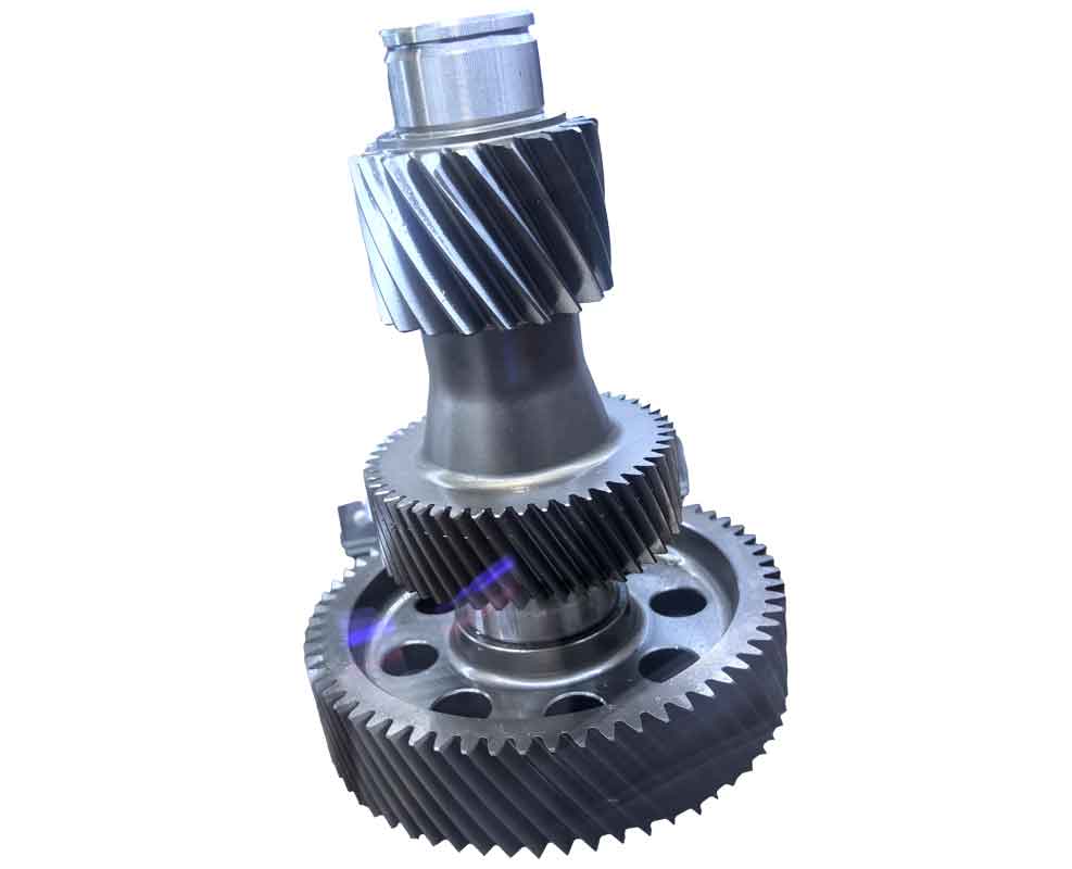
The image above illustrates a typical setup for gear cutting of spiral bevel gears, highlighting the complexity and precision required in the process. In my work, such visualizations aid in understanding the spatial relationships during gear cutting, complementing the mathematical models. The gear cutting parameters optimized through TCA are applied in similar configurations to achieve the desired tooth geometry. This holistic approach, combining theory, simulation, and practical gear cutting, ensures that the final products meet stringent quality standards. As gear cutting technology evolves, the integration of digital tools will continue to play a pivotal role in enhancing efficiency and accuracy, paving the way for smarter manufacturing in the gear industry.