
In the realm of mechanical transmission systems, bevel gears play a pivotal role, and among them, epicycloid bevel gears have garnered significant attention due to their superior performance characteristics such as high efficiency, robust load-bearing capacity, and low noise. The gear cutting process for these gears, however, poses considerable challenges, especially in terms of precision and equipment dependency. Traditionally, the manufacturing of epicycloid bevel gears relied heavily on imported mechanical machines, which are not only costly but also cumbersome to maintain, thereby stifling advancements in domestic gear production. With the advent of computer numerical control (CNC) technology, there is a pressing need to develop autonomous, high-precision gear cutting solutions. This article delves into the feasibility and implementation of gear cutting for epicycloid bevel gears using a five-axis, four-linkage CNC machine, a pioneering effort in domestic research. We will explore the underlying principles, mathematical modeling, parameter configuration, and experimental validation, emphasizing the gear cutting process throughout. The goal is to provide a comprehensive framework that supports the independent development of advanced gear cutting equipment, ultimately enhancing the competitiveness of local manufacturing industries.
The formation principle of epicycloid bevel gears is rooted in the generation of an epicycloidal tooth trace. Unlike the tapered teeth of spiral bevel gears, epicycloid gears feature constant-height teeth, which are produced through a continuous indexing method during gear cutting. In this process, a cutter head, equipped with multiple blade groups, interacts with a virtual generating gear to trace out an elongated epicycloid curve. The cutter head’s rotation must be precisely synchronized with the workpiece’s rotation to ensure accurate tooth division, a critical aspect of the gear cutting operation. This synchronization is achieved by establishing a specific speed ratio between the cutter spindle and the workpiece axis, facilitated by electronic gearbox (EGB) functionality in modern CNC systems. The geometric relationship involves a rolling motion between a circle on the cutter head and a base circle on the generating gear, culminating in the desired tooth profile. Understanding this principle is fundamental to optimizing the gear cutting parameters and achieving high-quality gears with minimal deviations.
Our research utilizes a JD600DX five-axis, four-linkage CNC machine, specifically designed for gear cutting applications. This machine represents a significant departure from conventional mechanical setups, as it eliminates complex mechanisms like the cradle and drum, instead relying on servo-driven interpolation for motion control. The machine’s structure comprises several axes: X, Y, and Z linear axes for positioning the cutter head and workpiece, along with rotational axes for the cutter spindle (A-axis) and workpiece (B-axis). A manually controlled rotary table adjusts the workpiece installation angle. Key features include rigid construction, patented design, hardened guideways, and full enclosure for both dry and wet gear cutting operations. The integration of EGB allows for seamless speed coupling between the cutter and workpiece, essential for continuous indexing during gear cutting. This CNC platform enables flexible adjustments through digital inputs, enhancing the efficiency and precision of the gear cutting process. By leveraging this technology, we aim to demonstrate that complex gear cutting tasks, such as those for epicycloid bevel gears, can be accomplished with domestically developed equipment, reducing reliance on foreign imports.
To effectively implement gear cutting on this CNC machine, a detailed mathematical model must be established. This model translates the traditional mechanical gear cutting kinematics into a CNC-compatible framework. We begin by defining coordinate systems for the cutter blades, cutter head, virtual generating gear, and workpiece. For instance, the cutter blade coordinates are expressed in terms of blade parameters, such as the tool profile angle and radial corrections. The transformation from blade coordinates to cutter head coordinates involves rotation matrices that account for the blade orientation and spacing. Subsequently, the cutter head’s position relative to the virtual generating gear is described using radial and angular tool settings. The core challenge lies in emulating the cradle rotation—a motion inherent in mechanical machines—through coordinated movements of the X and Y axes on the CNC machine. This virtual cradle rotation, combined with synchronized workpiece rotation, generates the epicycloidal tooth surface. The mathematical derivation yields the tooth surface equation and its unit normal vector, which are crucial for subsequent analysis and simulation.
The tooth surface equation for a right-hand gear, cut with a left-hand cutter, can be derived as follows. Let the cutter blade coordinates be represented as \( \mathbf{r}_{1k}(u_k) \), where \( k \) denotes inner (i) or outer (a) blades, \( u_k \) is the blade parameter, and \( \alpha_k \) is the tool profile angle. In the cutter head coordinate system \( S_2 \), the blade positions are transformed using rotation matrices \( \mathbf{M}_{21} \) and \( \mathbf{M}_{22′} \):
$$ \mathbf{r}_{2i}(u_i) = \mathbf{M}_{21} \mathbf{r}_{1i}(u_i) $$
$$ \mathbf{r}_{2a}(u_a) = \mathbf{M}_{22′} \mathbf{M}_{2’1′} \mathbf{r}_{1’a}(u_a) $$
These are generalized as \( \mathbf{r}_{2k} \). Next, in the virtual generating gear coordinate system \( S_4 \), the cutter head’s motion is incorporated through a rotation angle \( \varphi \):
$$ \mathbf{r}_{4k}(u_k, \varphi) = \mathbf{M}_{43} \mathbf{M}_{32} \mathbf{r}_{2k}(u_k) $$
The unit normal vector \( \mathbf{n}_{4k} \) is computed as the cross product of partial derivatives. Finally, for the workpiece coordinate system \( S \), additional rotations account for indexing and generating motions. The workpiece rotation angles include an indexing component \( \varphi_g’ \) and a generating component \( \varphi_g \), related to the cutter head rotation and virtual cradle rotation. The full transformation yields the gear tooth surface equation:
$$ \mathbf{r}_k(u_k, \varphi, \psi) = \mathbf{M}_{9} \mathbf{M}_{98} \mathbf{M}_{87} \mathbf{M}_{76} \mathbf{M}_{65} \mathbf{M}_{54} \mathbf{r}_{4k}(u_k, \varphi) $$
$$ \mathbf{n}_k(u_k, \varphi, \psi) = \mathbf{L}_{9} \mathbf{L}_{98} \mathbf{L}_{87} \mathbf{L}_{76} \mathbf{L}_{65} \mathbf{L}_{54} \mathbf{n}_{4k}(u_k, \varphi) $$
Here, \( \psi \) represents the virtual cradle rotation angle. This model ensures that the gear cutting process on the CNC machine accurately replicates the traditional method, enabling precise tooth geometry.
Setting up the machine parameters for gear cutting involves calculating the real-time coordinates for each axis during the operation. The CNC machine’s coordinate system is defined with an absolute origin, and key points such as the virtual cradle center and cutter head center are determined based on gear design parameters. The radial tool setting \( E_x \) and angular tool setting \( q \) define the cutter head’s position relative to the cradle. During gear cutting, the X and Y axes perform circular interpolation to simulate cradle rotation, while the workpiece axis receives additional angular increments to compensate for the lack of physical cradle motion. The coupling coefficient for the EGB is set as \( i = -z_0 / z \), where \( z_0 \) is the number of blade groups and \( z \) is the number of workpiece teeth. This ensures precise indexing. The coordinates for the cutter head at any time during generating motion are given by:
$$ X_{O2} = X_p – E_x \cos(q_q + \Delta q) $$
$$ Y_{O2} = Y_p + E_x \sin(q_q + \Delta q) $$
where \( X_p \) and \( Y_p \) are the virtual cradle center coordinates, \( q_q \) is the starting angular tool setting, and \( \Delta q \) is the change in tool setting during generating. The additional rotation angle for the workpiece axis, \( \Delta \phi_B \), is computed as:
$$ \Delta \phi_B = \frac{z_0 \Delta q}{z} + \frac{z_p \Delta q}{z} $$
with \( z_p \) as the number of generating gear teeth. These calculations are integral to programming the CNC machine for automated gear cutting. To illustrate, we provide a sample of coordinate data for both pinion and gear cutting processes, derived from a specific gear pair. This data guides the axis movements, ensuring that each gear cutting step is executed with high accuracy.
The following table summarizes key gear parameters used in our experimental validation. These parameters are essential for configuring the gear cutting process, including tool selection and machine settings.
| Parameter | Gear (Right-Hand) | Pinion (Left-Hand) |
|---|---|---|
| Number of Teeth | 28 | 17 |
| Pitch Cone Angle (°) | 58.736 | 31.264 |
| Mounting Distance (mm) | 113 | 162 |
| Shaft Angle (°) | 90 | |
| Offset Distance (mm) | 0 | |
| Normal Module at Reference Point (mm) | 7.237 | |
| Face Width (mm) | 50 | |
| Spiral Angle at Reference Point (°) | 36.633 | |
| Cone Distance at Reference Point (mm) | 147.7 | |
Additionally, cutter head parameters are critical for gear cutting. We employed TC5—88 cutter heads, with specific adjustments for tangential radius and blade orientation. The table below outlines these parameters, which influence tooth profile accuracy during gear cutting.
| Cutter Head Parameter | Left-Hand Cutter (Gear) | Right-Hand Cutter (Pinion) |
|---|---|---|
| Number of Blade Groups | 5 | |
| Cutter Tangent Radius (mm) | 88 | |
| Tangential Radius Correction (mm) | 1.13 | 1.03 |
| Cutter Eccentricity Adjustment (mm) | 18.7 | |
| Tool Profile Angle (°) | 17.5 | |
| Number of Generating Gear Teeth | 32.757 | |
Machine settings for gear cutting are derived from the above parameters. These include radial and angular tool settings, machine root angle, and motion limits. The table presents the configured values for both gear and pinion cutting, ensuring proper engagement during gear cutting operations.
| Machine Setting | Gear Cutting | Pinion Cutting |
|---|---|---|
| Radial Tool Setting (mm) | 136.62 | 136.62 |
| Angular Tool Setting (°) | 36.631 | -36.631 |
| Machine Root Angle (°) | 58.736 | 31.264 |
| Vertical Workpiece Setting (mm) | 0 | |
| Workpiece Setting Correction (mm) | 0 | |
| Ratio of Roll | 1.169881 | 1.926863 |
| Starting Tool Setting (°) | 41.631 | -41.631 |
| Ending Tool Setting (°) | 21.631 | -21.631 |
| Cutter Spindle Speed (rpm) | -60 | 60 |
| Coupling Coefficient | -5/28 | -5/17 |
| Fixture Thickness (mm) | 75.97 | 260 |
To validate the gear cutting theory, we conducted tooth contact analysis (TCA) simulations prior to actual machining. TCA predicts the contact pattern and transmission errors, providing insights into gear performance. For the 28/17 gear pair, the simulation indicated that the gear convex side contact area is near the toe at the center, while the concave side contact is toward the toe at the top. These results guide adjustments in gear cutting parameters to optimize contact patterns. Following simulation, we proceeded with physical gear cutting experiments on the JD600DX CNC machine. The process flowchart for gear cutting includes steps such as positioning axes, activating EGB, feeding the Z-axis for depth control, performing generating motion via X-Y interpolation, and retracting. Each step is carefully programmed based on the mathematical model to ensure precision.
During gear cutting, real-time coordinate data for the axes were recorded at intervals of 0.1° in generating angle change. For pinion cutting, the X and Y coordinates, along with the corresponding changes in angular tool setting and workpiece rotation, are tabulated below. This data exemplifies the dynamic movements required in gear cutting, highlighting the synchronization between axes.
| Point | X (mm) | Y (mm) | Δq (°) | ΔφB (°) |
|---|---|---|---|---|
| 0 | -211.282 | -358.720 | 0.0 | 0.000 |
| 1 | -211.469 | -358.571 | 0.1 | 0.222 |
| 2 | -211.655 | -358.423 | 0.2 | 0.444 |
| … | … | … | … | … |
| 298 | -253.300 | -302.410 | 29.8 | 66.185 |
| 299 | -253.388 | -302.188 | 29.9 | 66.407 |
| 300 | -253.476 | -301.967 | 30.0 | 66.629 |
Similarly, for gear cutting, the coordinate data reflects the reverse motion due to the opposite hand of cut. This detailed logging ensures reproducibility in gear cutting operations.
| Point | X (mm) | Y (mm) | Δq (°) | ΔφB (°) |
|---|---|---|---|---|
| 0 | -378.683 | -144.494 | 0.0 | 0.000 |
| 1 | -378.870 | -144.643 | -0.1 | -0.135 |
| 2 | -379.056 | -144.791 | -0.2 | -0.270 |
| … | … | … | … | … |
| 298 | -420.701 | -200.804 | -29.8 | -40.184 |
| 299 | -420.790 | -201.026 | -29.9 | -40.319 |
| 300 | -420.878 | -201.247 | -30.0 | -40.454 |
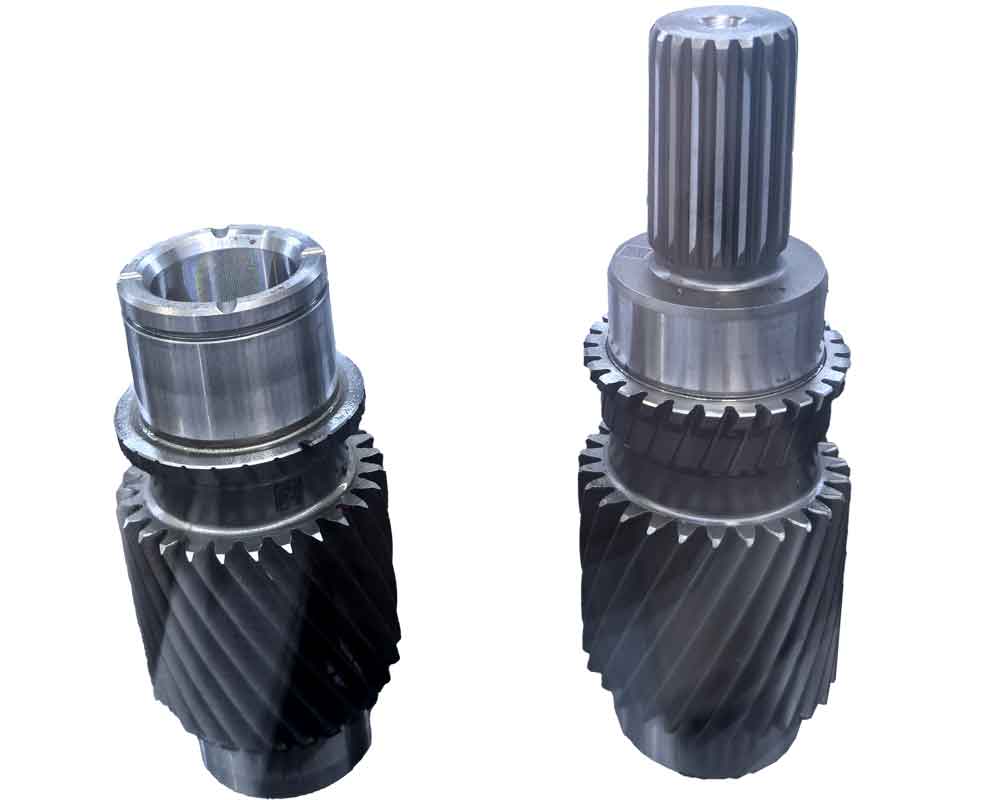
The gear cutting trials were successfully conducted, resulting in a pair of epicycloid bevel gears. Post-cutting, the gears were subjected to rolling inspection to evaluate the contact pattern. The observed contact area on the gear convex side was centrally located slightly toward the toe, and on the concave side, it was near the toe at the top, closely matching the TCA predictions. This alignment confirms the accuracy of our gear cutting methodology and the effectiveness of the CNC machine in producing high-quality gears. The successful replication of desired contact patterns underscores the viability of four-axis linkage gear cutting for epicycloid bevel gears, paving the way for further advancements in domestic gear manufacturing technology.
In conclusion, our research demonstrates that gear cutting for epicycloid bevel gears can be effectively performed on a five-axis, four-linkage CNC machine through careful mathematical modeling and parameter optimization. The key innovation lies in compensating for the absence of physical cradle motion by coordinating axis movements and adjusting workpiece rotation, thereby emulating traditional gear cutting kinematics. The experimental results validate the theoretical approach, yielding gears with satisfactory contact patterns. This work not only provides a practical framework for gear cutting but also contributes to the autonomous development of advanced gear production equipment, reducing dependency on imported technology. Future efforts will focus on refining the gear cutting process for broader applications and integrating real-time monitoring to enhance precision and efficiency in gear manufacturing.