
In the field of mechanical transmission, the development of high-performance gears is crucial for advancing industrial applications. Among these, bi-directional circular arc gears have garnered significant attention due to their superior load-bearing capacity, compact spatial dimensions, and reliable operation. These gears are increasingly being adopted in sectors such as petroleum machinery, where durability and efficiency are paramount. However, the unique geometry of bi-directional circular arc gears presents distinct challenges in their design and manufacturing. Unlike conventional double circular arc gears or helical gears, the teeth of bi-directional circular arc gears are arched, with varying helical angles across different axial cross-sections. This complexity means that the tooth profile formation differs along the axial direction, making traditional gear cutting simulation methods inadequate. Therefore, leveraging computer simulation technology to study these gears is essential. By dynamically visualizing the gear cutting process and pre-displaying tooth profiles on a computer screen, we can overcome research hurdles and optimize manufacturing processes. This article delves into the mathematical modeling and computer simulation of the gear cutting envelope for bi-directional circular arc gears, emphasizing the role of advanced simulation in enhancing gear cutting precision and efficiency.
The core of simulating gear cutting for bi-directional circular arc gears lies in understanding the generating cutting principle. These gears are typically machined using a Gleason cutter head based on the envelope theory. In this process, the cutter teeth form a virtual tool rack that meshes with the gear being cut. The cutter head rotates to perform the primary cutting motion while simultaneously moving tangentially via a tangent tool post. The gear blank rotates in sync with this tangential motion, ensuring that the circumferential velocity at the pitch circle equals the tangential velocity of the cutter. This setup mimics the meshing motion between the tool rack and the gear, facilitating the generating cutting of the tooth surface. Since there is no axial movement between the tool rack and the gear, the tooth profile in any axial cross-section is formed by the envelope of the tool rack’s profile in that same section during the generating motion. Thus, the complex spatial gear cutting problem is reduced to a planar generating cutting issue in axial cross-sections, simplifying the simulation approach.
To establish a mathematical model for gear cutting simulation, we first define coordinate systems. Let the gear coordinate system be denoted as \( S_g: [O_g, X_g, Y_g, Z_g] \), and the tool rack coordinate system as \( S_t: [O_t, X_t, Y_t, Z_t] \). The tool rack’s profile is based on the GB/T 12759-1991 standard for double circular arc基准 tooth forms, consisting of multiple circular arcs. For simulation, we store the parameters of these arcs in arrays, such as the center coordinates \((X_c, Y_c)\), radii \(R\), and start and end angles \(\theta_s, \theta_e\). By considering an arbitrary axial cross-section at position \(z = z_0\) (a constant), we can derive the tool rack’s profile curve in that section. The transformation from the tool rack’s normal profile to the axial cross-section involves accounting for the helical angle variations. The general equation for the tool rack’s profile curve in section \(z = z_0\) is given by:
$$ \begin{cases}
X_t = [R \cos(\theta) + X_c] \cdot \cos(\beta) – [R \sin(\theta) + Y_c] \cdot \sin(\beta) + \Delta_x, \\
Y_t = [R \cos(\theta) + X_c] \cdot \sin(\beta) + [R \sin(\theta) + Y_c] \cdot \cos(\beta) + \Delta_y,
\end{cases} $$
where \(\beta\) is the helical angle at the cross-section, \(\theta\) is the angular parameter along the arc, and \(\Delta_x, \Delta_y\) are displacement adjustments due to tool alignment errors during gear cutting. The helical angle \(\beta\) varies with \(z_0\), and its relationship can be expressed as \(\beta = \beta_0 + k \cdot z_0\), with \(\beta_0\) as the reference helical angle and \(k\) as a constant factor. This variation is key to accurately simulating the gear cutting process for bi-directional circular arc gears.
The generating motion between the tool rack and gear blank is governed by planar enveloping conditions. For a point \((X_t, Y_t)\) on the tool rack’s profile to become a contact point on the gear tooth, the relative velocity must satisfy the envelope condition. Let the gear blank’s rotation angle be \(\phi\), and the tool rack’s displacement be \(s = r_p \phi\), where \(r_p\) is the pitch radius. The condition for contact is derived from the equation of meshing:
$$ \frac{\partial Y_t}{\partial \theta} \cdot \frac{dX_t}{d\phi} – \frac{\partial X_t}{\partial \theta} \cdot \frac{dY_t}{d\phi} = 0. $$
By differentiating the tool rack profile equations and substituting into the above, we obtain the gear blank’s rotation angle \(\phi\) corresponding to contact points. The formula simplifies to:
$$ \phi = \arctan\left( \frac{Y_t – \Delta_y}{X_t – \Delta_x} \right) – \frac{s}{r_p}. $$
This equation allows us to compute the precise rotation angles during gear cutting simulation, ensuring accurate envelope formation.
Transforming contact points to the gear coordinate system yields the coordinates of the gear tooth profile. Using homogeneous transformation matrices, the gear tooth point \((X_g, Y_g)\) is calculated as:
$$ \begin{pmatrix} X_g \\ Y_g \\ 1 \end{pmatrix} = \begin{pmatrix} \cos(\phi) & -\sin(\phi) & r_p \phi \\ \sin(\phi) & \cos(\phi) & 0 \\ 0 & 0 & 1 \end{pmatrix} \begin{pmatrix} X_t \\ Y_t \\ 1 \end{pmatrix}. $$
This transformation accounts for both rotation and translation during the generating motion. By iterating over all points on the tool rack’s profile and their corresponding \(\phi\) values, we can generate the complete tooth profile for any axial cross-section. This mathematical foundation is essential for computer simulation of gear cutting processes.
To implement the gear cutting simulation, we developed a software tool using C++ on a PC platform. The software integrates modules for data management, geometric computation, simulation control, and visualization. A key feature is the use of a database to store standard tooth profile parameters based on GB/T 12759-1991, allowing retrieval based on normal modulus \(m_n\). The simulation process involves several steps: first, determining the axial cross-section position \(z_0\); second, computing the tool rack’s profile curve for that section using the equations above; third, calculating the gear blank’s rotation range for each tooth; and finally, simulating the continuous motion of the tool rack to envelope the gear tooth profile. The flowchart of the simulation program is summarized in Table 1, illustrating the procedural steps.
| Step | Action | Description |
|---|---|---|
| 1 | Initialize Simulation | Load gear parameters (e.g., modulus, tooth count) and tool data from database. |
| 2 | Select Axial Cross-section | Set \(z_0\) value to define the section for gear cutting simulation. |
| 3 | Compute Tool Rack Profile | Use equations (1) and (2) to generate profile curve for section \(z_0\). |
| 4 | Determine Rotation Angles | Calculate \(\phi_{\text{start}}\) and \(\phi_{\text{end}}\) for each tooth using envelope condition. |
| 5 | Simulate Generating Motion | Animate tool rack movement over \(\phi\) range to envelope tooth profile. |
| 6 | Visualize Results | Display dynamic cutting process and final tooth profile on screen. |
| 7 | Output Data | Export simulation results for analysis or plotting. |
The simulation software enables interactive control via keyboard inputs, allowing users to adjust parameters such as gear cutting speed and simulation precision through pop-up menus. This flexibility is vital for exploring different gear cutting scenarios. For instance, users can simulate multiple axial cross-sections simultaneously to observe variations in tooth profiles along the gear axis. The software also supports output to plotters for precise drafting of simulated tooth profiles, facilitating further analysis of gear cutting accuracy and meshing performance.
During gear cutting simulation, the tool rack’s profile moves continuously within the computed rotation angle range for each tooth. This motion generates the envelope that forms the gear tooth shape. The process can be visualized dynamically, showing how contact points evolve and how the tool rack progresses during gear cutting. To illustrate this, the simulation captures key frames of the cutting process. For example, in one axial cross-section, the tool rack gradually removes material to form the arched tooth profile. The dynamic display helps identify potential issues in gear cutting, such as undercutting or profile errors, before physical manufacturing.
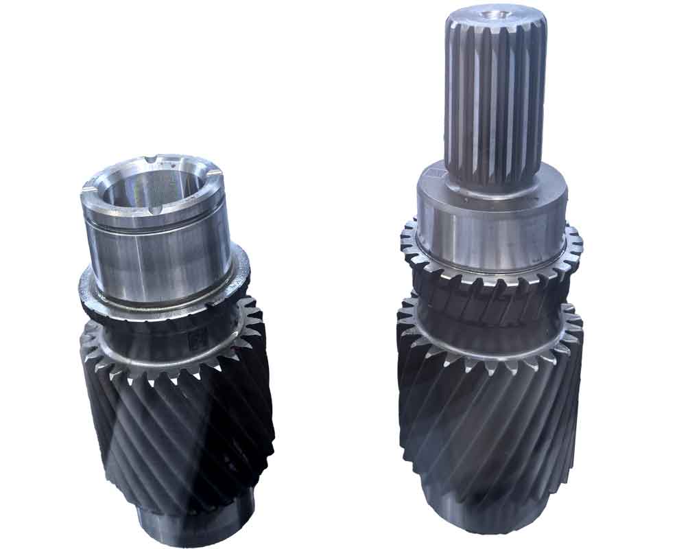
The image above provides a visual reference for gear cutting simulation outcomes, showcasing the intricate tooth profiles generated through computer simulation. Such visuals are instrumental in validating the gear cutting process and ensuring design correctness. In our simulations, we observed that bi-directional circular arc gears exhibit significant tooth profile variations across axial sections. For instance, at the gear’s center section (\(z_0 = 0\)), the tooth profile might differ from that at the ends (\(z_0 = \pm L/2\), where \(L\) is gear width). These variations are attributed to the changing helical angles, which affect the tool rack’s engagement during gear cutting. Table 2 summarizes typical parameters used in our simulations, highlighting factors influencing gear cutting results.
| Parameter | Symbol | Value Range | Description |
|---|---|---|---|
| Normal Modulus | \(m_n\) | 2–10 mm | Defines tooth size; retrieved from database for gear cutting. |
| Helical Angle at Center | \(\beta_0\) | 15°–30° | Base helical angle affecting tooth curvature in gear cutting. |
| Axial Position | \(z_0\) | -L/2 to L/2 | Cross-section location for simulation of gear cutting. |
| Tool Radius | \(R_t\) | 50–200 mm | Cutter head radius influencing gear cutting path. |
| Pitch Radius | \(r_p\) | \(m_n \cdot Z / 2\) | Gear blank radius critical for generating motion in gear cutting. |
| Tooth Count | \(Z\) | 20–100 | Number of teeth affecting gear cutting complexity. |
By simulating gear cutting across these parameters, we can analyze the envelope formation in detail. The mathematical model ensures that each point on the tool rack’s profile contributes to the gear tooth only when the envelope condition is met. This precision is crucial for accurate gear cutting simulation. For example, the gear blank’s rotation angle \(\phi\) for a given tool rack point is computed iteratively, and the resulting tooth profile coordinates are stored for visualization. The simulation software uses these coordinates to render the cutting process in real-time, allowing users to pause, zoom, and inspect specific gear cutting stages.
One of the key advantages of computer simulation in gear cutting is the ability to predict and rectify errors before actual manufacturing. In bi-directional circular arc gears, common issues include profile deviations due to tool misalignment or helical angle miscalculations. Our simulation incorporates error terms \(\Delta_x\) and \(\Delta_y\) to account for tool positioning inaccuracies during gear cutting. By adjusting these terms, users can simulate imperfect gear cutting conditions and observe their impact on tooth profiles. This proactive approach enhances the reliability of gear cutting processes, reducing scrap rates and improving product quality.
The simulation results reveal that the tooth profiles of bi-directional circular arc gears are highly sensitive to axial position. For instance, the curvature of the tooth flank changes gradually from the center to the ends, as shown by the simulated profiles. This variation must be carefully controlled during gear cutting to ensure proper meshing with mating gears. The software allows superimposing multiple axial section profiles for comparative analysis, as illustrated in Figure 2 of the simulation output. Such comparisons are vital for optimizing gear cutting parameters to achieve uniform load distribution and minimal noise in operation.
To further elucidate the gear cutting mechanics, we can derive additional formulas for specific scenarios. For example, the contact ratio during gear cutting can be estimated by analyzing the number of tool rack points in contact over a rotation interval. The contact ratio \(C_r\) is given by:
$$ C_r = \frac{\phi_{\text{contact}}}{\phi_{\text{pitch}}}, $$
where \(\phi_{\text{contact}}\) is the rotation angle over which at least one tool rack point is in contact, and \(\phi_{\text{pitch}}\) is the angular pitch between teeth. This ratio influences the smoothness of gear cutting and subsequent gear operation. In our simulations, \(C_r\) typically ranges from 1.2 to 1.8, indicating stable gear cutting conditions.
Another important aspect is the simulation of gear cutting for multiple teeth simultaneously. The software computes the tool rack’s profile for each tooth index \(i\) (where \(i = 1, 2, \dots, Z\)) using the displacement adjustment \(s_i = i \cdot p + \Delta_s\), with \(p\) as the circular pitch and \(\Delta_s\) as a cumulative error term. This allows realistic simulation of full gear cutting processes, where all teeth are generated sequentially. The algorithm efficiently handles this by pre-calculating profile curves for all teeth and animating their enveloping motions in parallel. This capability is essential for comprehensive gear cutting analysis, as it mirrors actual manufacturing setups.
The integration of computer simulation in gear cutting research offers profound benefits. Firstly, it reduces the need for physical prototypes, saving time and costs. Secondly, it enables detailed study of tooth profile accuracy and gear cutting dynamics under various conditions. For bi-directional circular arc gears, this is particularly valuable due to their complex geometry. Our simulation tool has been used to optimize gear cutting parameters for petroleum machinery applications, resulting in gears with enhanced durability and performance. The ability to visualize the gear cutting process in real-time has also aided in training engineers and technicians, fostering a deeper understanding of gear manufacturing principles.
In terms of software implementation, the gear cutting simulation modules are designed for extensibility. New tooth profile standards or cutter designs can be incorporated by updating the parameter database and profile equations. The user interface provides intuitive controls for adjusting gear cutting speed, resolution, and output formats. For instance, users can select between high-precision simulation for research purposes or faster simulation for preliminary design checks. This flexibility makes the tool suitable for both academia and industry, supporting advancements in gear cutting technology.
Looking ahead, future work could enhance the gear cutting simulation by incorporating thermal and mechanical deformation models. During actual gear cutting, factors like tool wear and heat generation affect the final tooth profile. By integrating finite element analysis (FEA) with the envelope simulation, we could predict these effects and further refine gear cutting parameters. Additionally, real-time simulation on advanced hardware could enable virtual reality (VR) applications, allowing immersive inspection of gear cutting processes. Such innovations would push the boundaries of gear manufacturing, making gear cutting more efficient and precise.
In conclusion, computer simulation of gear cutting envelopes for bi-directional circular arc gears is a powerful methodology that addresses the challenges posed by their unique geometry. Through mathematical modeling based on generating principles and envelope conditions, we can accurately simulate tooth profile formation in any axial cross-section. The developed software provides dynamic visualization and interactive control, facilitating in-depth analysis of gear cutting processes. By repeatedly emphasizing gear cutting in this discourse, we underscore its centrality to gear manufacturing. The simulation results not only validate design correctness but also pave the way for optimized production, ensuring that bi-directional circular arc gears meet the demanding requirements of modern applications. As gear cutting technology evolves, such simulations will remain indispensable for innovation and quality assurance in mechanical transmission systems.