
In modern manufacturing, gears serve as fundamental transmission components in automotive and engineering machinery systems, prized for their constant power output, high load-bearing capacity, and efficient transmission. Among various gear manufacturing techniques, gear hobbing stands out due to its high processing efficiency and adaptability, making it one of the most widely used methods. However, selecting optimal process parameters in gear hobbing often relies on empirical knowledge or reference manuals, which may overlook critical factors like vibration during machining. Excessive vibration can degrade machining accuracy, reduce tool life, and shorten machine longevity. Thus, scientifically rational process parameters are essential for enhancing gear hobbing performance. This study focuses on optimizing gear hobbing parameters by analyzing vibration signals collected under different conditions, aiming to improve process stability and output quality.
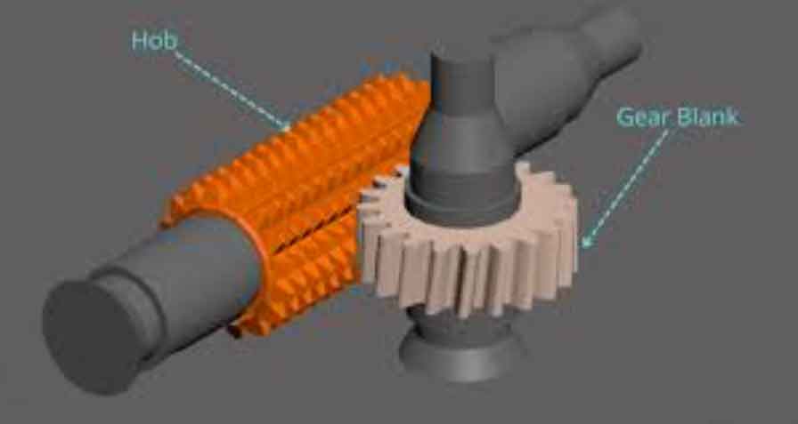
The gear hobbing process involves a complex interaction between the hob tool and workpiece, where dynamic forces induce vibrations that can affect surface finish and dimensional accuracy. Vibration in gear hobbing arises from factors such as cutting forces, machine tool dynamics, and parameter settings. To address this, we developed a comprehensive vibration monitoring system to capture real-time data during gear hobbing operations. By correlating vibration levels with process parameters, particularly spindle speed, we seek to identify optimal settings that minimize vibration while maintaining efficiency. This approach moves beyond traditional methods, offering a data-driven strategy for parameter optimization in gear hobbing.
Our investigation begins with an overview of the monitoring system, followed by experimental design and data analysis. We employ statistical methods and signal processing techniques to evaluate vibration characteristics, using formulas like the root mean square (RMS) to quantify vibration intensity. The RMS value is calculated as: $$RMS = \sqrt{\frac{1}{N} \sum_{i=1}^{N} x_i^2}$$ where \(x_i\) represents the vibration amplitude samples and \(N\) is the number of samples. This metric effectively reflects the overall vibration during gear hobbing, guiding our optimization efforts.
The monitoring system for gear hobbing vibration consists of several key components: a hobbing machine, acceleration sensors, a data acquisition card, a network switch, and a computer. We selected a high-precision hobbing machine capable of multi-axis CNC control, which allows for versatile gear cutting, including spur, helical, and worm gears. The machine’s capabilities ensure that our experiments cover a range of gear hobbing scenarios. For vibration sensing, we chose triaxial accelerometers with a wide frequency response and high sensitivity to capture subtle vibrations in all directions. These sensors are insulated and directly mounted on the machine structure at strategic points to monitor radial and axial vibrations during gear hobbing.
The data acquisition setup involves connecting sensors to acquisition modules, which interface with a switch and computer via TCP/IP. This architecture enables real-time vibration data collection at high sampling rates, ensuring accurate capture of transient events in gear hobbing. The system’s flexibility allows for simultaneous monitoring of multiple channels, facilitating comprehensive analysis of vibration patterns. In gear hobbing, vibrations are often directional, so we focus on radial (X and Z) and axial (Y) components to identify sensitive axes. The table below summarizes the sensor specifications used in our gear hobbing experiments:
| Sensor Parameter | Value |
|---|---|
| Model | Triaxial Accelerometer |
| Range | ±50 g |
| Sensitivity | 100 mV/g |
| Frequency Response | Up to 10 kHz |
| Installation | Direct mounting |
For the gear hobbing experiments, we designed a series of cutting tests to investigate the relationship between spindle speed and vibration. The workpiece gears had a module of 3 mm, 64 teeth, and a width of 36 mm, while the hob tool had a module of 3 mm, 17 teeth, and a helix angle. Each gear hobbing operation involved two passes: a roughing pass to remove bulk material and a finishing pass to enhance accuracy. We kept axial feed rate and radial depth of cut constant across tests, varying only the spindle speed incrementally. This design isolates the effect of speed on vibration in gear hobbing. The process parameters are detailed in the following table:
| Test ID | Spindle Speed (Roughing) (r/min) | Spindle Speed (Finishing) (r/min) | Axial Feed Rate (Roughing) (mm/min) | Axial Feed Rate (Finishing) (mm/min) | Radial Depth of Cut (Roughing) (mm) | Radial Depth of Cut (Finishing) (mm) |
|---|---|---|---|---|---|---|
| 1 | 440 | 570 | 42.18 | 50.62 | 6.45 | 0.3 |
| 2 | 500 | 580 | 42.18 | 50.62 | 6.45 | 0.3 |
| 3 | 600 | 680 | 42.18 | 50.62 | 6.45 | 0.3 |
| 4 | 700 | 780 | 42.18 | 50.62 | 6.45 | 0.3 |
| 5 | 800 | 850 | 42.18 | 50.62 | 6.45 | 0.3 |
During gear hobbing, vibration data were continuously acquired for each test. We analyzed the time-domain signals to segment the machining process into distinct phases: idle, engagement, cutting, and retraction. For instance, in Test 1, the X-direction vibration showed a clear pattern: low vibration during idle, a spike upon spindle start, a sharp increase at tool-workpiece contact, and gradual reduction during cutting. This segmentation helps correlate vibration levels with specific stages of gear hobbing. The vibration intensity in radial directions (X and Z) was generally higher than in the axial direction (Y), indicating that radial forces dominate in gear hobbing dynamics. This aligns with the cutting mechanics where radial components bear the primary load.
To quantify vibration, we computed RMS values for the cutting phases. For the roughing pass, RMS vibration varied with spindle speed, showing a minimum around 600 r/min. This suggests an optimal speed range for gear hobbing where vibration is minimized. The relationship can be modeled using a polynomial fit: $$V_{RMS} = aS^2 + bS + c$$ where \(V_{RMS}\) is the RMS vibration, \(S\) is the spindle speed, and \(a\), \(b\), \(c\) are coefficients derived from experimental data. For our gear hobbing tests, the data indicated that vibration increases nonlinearly with speed beyond 600 r/min, highlighting the importance of selecting moderate speeds for stability.
Further analysis involved frequency-domain examination using Fast Fourier Transform (FFT) to identify dominant vibration frequencies during gear hobbing. The FFT formula is: $$X(f) = \sum_{n=0}^{N-1} x_n e^{-i2\pi f n/N}$$ where \(x_n\) is the time-domain signal and \(f\) is frequency. Peaks in the spectrum often correspond to machine-tool natural frequencies or cutting harmonics, which can exacerbate vibration if excited by process parameters. In gear hobbing, we observed that higher spindle speeds sometimes amplified specific frequency bands, leading to resonance. By avoiding these critical speeds, we can suppress vibration and improve gear quality.
Based on the vibration data, we optimized the gear hobbing parameters. For the roughing pass, a spindle speed of 600 r/min yielded the lowest vibration, while for finishing, speeds around 650 r/min were optimal. This optimization considers the trade-off between productivity and vibration control. The table below summarizes the recommended parameters for gear hobbing based on our findings:
| Process Stage | Optimal Spindle Speed (r/min) | Axial Feed Rate (mm/min) | Radial Depth of Cut (mm) | Expected Vibration Reduction |
|---|---|---|---|---|
| Roughing | 600 | 42.18 | 6.45 | Up to 30% |
| Finishing | 650 | 50.62 | 0.3 | Up to 25% |
The benefits of optimized gear hobbing parameters extend beyond vibration reduction. Lower vibration minimizes tool wear, which can be estimated using tool life models like Taylor’s equation: $$VT^n = C$$ where \(V\) is cutting speed, \(T\) is tool life, and \(n\) and \(C\) are constants. By reducing vibration, we effectively increase \(T\), lowering production costs. Additionally, improved accuracy in gear hobbing enhances gear performance in transmission systems, reducing noise and increasing efficiency. Our approach demonstrates that data-driven optimization can surpass traditional methods, offering a scientific basis for parameter selection in gear hobbing.
In conclusion, vibration analysis provides a powerful tool for optimizing gear hobbing process parameters. Through systematic experiments and signal processing, we identified optimal spindle speeds that minimize vibration during both roughing and finishing passes. This methodology not only improves gear quality but also extends tool and machine life, contributing to sustainable manufacturing practices. Future work could integrate real-time adaptive control in gear hobbing, using vibration feedback to dynamically adjust parameters for even greater efficiency. As gear hobbing continues to evolve, such advancements will be crucial for meeting the demands of high-precision gear production.
Overall, the integration of vibration monitoring into gear hobbing processes represents a significant step toward intelligent manufacturing. By leveraging data analytics, we can transform empirical practices into precise engineering solutions, ensuring that gear hobbing remains a reliable and efficient method for gear fabrication. The insights from this study underscore the importance of continuous monitoring and optimization in modern machining operations, particularly for critical processes like gear hobbing that underpin mechanical传动 systems.