
In modern manufacturing, gear hobbing stands as a critical process for producing high-precision gears, especially helical gears used in automotive, aerospace, and industrial machinery. As a researcher engaged in advanced manufacturing technologies, I have observed that high-speed dry hobbing, while efficient, introduces significant challenges due to dynamic machining conditions. The complex multi-axis synchronization required for helical gear hobbing often leads to synchronous errors that degrade gear quality. Traditional error compensation methods struggle with the non-stationary and nonlinear nature of these errors. In this article, we explore a novel approach based on wavelet packet analysis to decompose, reconstruct, and compensate for synchronous errors in helical gear hobbing. This method leverages signal processing techniques to enhance precision without increasing hardware costs, offering a practical solution for improving gear hobbing accuracy.
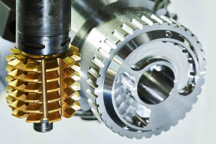
The gear hobbing process, particularly for helical gears, relies on precise coordination between multiple axes. In a typical CNC hobbing machine, such as the YK3126 model, there are six control axes: three linear axes (X, Y, Z) and three rotational axes (A, B, C). The B-axis drives the hob rotation, while the C-axis controls the workpiece rotation. For helical gear hobbing, two sets of electronic gearboxes are used to synchronize the B-C axis linkage and the Z-C axis linkage. The synchronous motion relationship is governed by the following equation:
$$n_C = K_B \frac{Z_B}{Z_C} \cdot n_B + K_Z \frac{360 \sin \beta}{\pi m z} \cdot v_Z$$
where \(n_C\) and \(n_B\) are the rotational speeds of the C-axis and B-axis in rpm, respectively; \(v_Z\) is the axial feed rate of the Z-axis in mm/min; \(\beta\) is the helix angle of the helical gear; \(m\) is the normal module in mm; \(z\) is the number of gear teeth; \(Z_B\) and \(Z_C\) are parameters related to the hob and gear; and \(K_B\) and \(K_Z\) are coefficients determined by the hob and gear handedness. For right-handed hobs and downward cutting, \(K_B = 1\) and \(K_Z = 1\). The synchronous error in gear hobbing arises from the linear superposition of errors from the B-C linkage and the Z-C linkage, making compensation complex due to the dynamic machining environment.
To address this, we propose a wavelet packet-based algorithm for error compensation. Wavelet packet analysis is a signal processing technique that provides multi-resolution analysis, allowing decomposition of signals into different frequency bands. This is particularly useful for non-stationary signals like those in gear hobbing, where errors contain components from various sources such as mechanical vibrations, thermal effects, and servo inaccuracies. The wavelet packet transform overcomes limitations of traditional Fourier analysis by offering localized time-frequency information. We define the wavelet packet functions recursively. Let \(\{h_n\}_{n \in \mathbb{Z}}\) be a sequence satisfying:
$$\sum_n h_{n-2k} h_{n-2l} = \delta_{k,l}, \quad \sum_n h_n = \sqrt{2}$$
Then, the wavelet packet functions \(u_n(t)\) for \(n = 0, 1, 2, \ldots\) are defined as:
$$u_0(t) = \phi(t), \quad u_1(t) = \psi(t)$$
$$u_{2n}(t) = \sqrt{2} \sum_k h_k u_n(2t – k)$$
$$u_{2n+1}(t) = \sqrt{2} \sum_k g_k u_n(2t – k)$$
where \(\phi(t)\) is the scaling function, \(\psi(t)\) is the wavelet function, and \(g_k\) is derived from \(h_k\). This allows decomposition of a signal \(S(t)\) into sub-bands for detailed analysis. In gear hobbing applications, we apply this to synchronous error signals collected during machining.
The synchronous error signal is acquired using a data acquisition system connected to the CNC controller. For instance, with a HNC-9 system, we use HNC-SSTT software to sample the error register D50, which represents the difference between the theoretical and actual angular displacement of the C-axis. The sampling frequency is set to 1000 Hz, yielding a Nyquist frequency of 500 Hz. During helical gear hobbing, the error signal encompasses components from both B-C and Z-C linkages, along with noise from environmental factors. Table 1 summarizes key parameters for a typical helical gear hobbing operation, which we used in our experiments.
| Parameter | Value | Parameter | Value |
|---|---|---|---|
| Normal Module (mm) | 3 | Number of Teeth | 59 |
| Hob Number of Starts | 3 | Feed per Revolution (mm/rev) | 1.5 |
| Pressure Angle (degrees) | 20 | Depth of Cut (mm) | 6.45 |
| Hob Handedness | Right | Hob Speed (rpm) | 680 |
| Gear Handedness | Right | Cutting Method | Upward Hobbing |
The raw synchronous error signal, shown in Figure 1 (though not referenced explicitly), exhibits fluctuations due to machining dynamics. To analyze this, we perform a 3-level wavelet packet decomposition using the db1 wavelet basis, which is chosen for its regularity. This decomposes the signal into \(2^3 = 8\) sub-bands, each with a bandwidth of 62.5 Hz. The decomposition tree is represented as:
$$S = S_{3,0} + S_{3,1} + S_{3,2} + S_{3,3} + S_{3,4} + S_{3,5} + S_{3,6} + S_{3,7}$$
where \(S_{3,i}\) denotes the signal at node \(i\) of the third level. By examining the amplitude distribution across these sub-bands, we identify that the primary error components reside in nodes 0 and 3, which correspond to low-frequency and mid-frequency bands. These bands contain the essential synchronous error features related to gear hobbing kinematics, while other nodes represent noise or insignificant perturbations. We reconstruct the error signal using only these significant nodes, effectively denoising the signal. The reconstructed error \(D’_{50}\) is given by:
$$D’_{50} = S_{3,0} + S_{3,3}$$
This reconstruction reduces the error amplitude significantly. For example, in our tests, the peak error decreased from 0.0514° to 0.0292°, a reduction of approximately 43%. This demonstrates the efficacy of wavelet packet analysis in isolating meaningful error components in gear hobbing.
Next, we decouple the reconstructed synchronous error into contributions from the B-C and Z-C linkages based on the principle of linear superposition. The error contributions are calculated as follows:
$$\Delta \phi_{BC} = \frac{Z_B}{Z_C} \cdot \Delta \delta_B$$
$$\Delta \phi_{ZC} = \frac{360 \sin \beta}{\pi m z} \cdot \Delta \delta_Z$$
where \(\Delta \phi_{BC}\) is the theoretical angular displacement from the B-axis to the C-axis, \(\Delta \delta_B\) is the incremental angular displacement of the B-axis, \(\Delta \phi_{ZC}\) is the theoretical angular displacement from the Z-axis to the C-axis, and \(\Delta \delta_Z\) is the incremental axial displacement of the Z-axis. The decoupled errors for compensation are:
$$D’_{50,(B-C)} = \frac{\Delta \phi_{BC}}{\Delta \phi_{BC} + \Delta \phi_{ZC}} \cdot D’_{50}$$
$$D’_{50,(Z-C)} = \frac{\Delta \phi_{ZC}}{\Delta \phi_{BC} + \Delta \phi_{ZC}} \cdot D’_{50}$$
These decoupled errors are then compensated inversely to the respective axes via modifications to the NC code. We implement this using electronic gearbox functions in the CNC system. The compensation parameters are set in the NC program as shown in Table 2, which outlines the electronic gearbox configuration for error compensation in gear hobbing.
| Parameter | Value | Description |
|---|---|---|
| #101 | 1 | Phase synchronization enabled |
| #102 | 0 | Phase deviation angle set to zero |
| #103 | 1 | C-axis command following enabled |
| #104 | 5 | Hob spindle axis number (B-axis) |
| #105 | 19.6664543 | Master axis B coefficient |
| #106 | 1 | Master axis Y number (for Z-axis linkage) |
| #107 | 2 | Master axis coefficient for Z linkage |
| #108 | 4.51617739 | Slave axis Z coefficient |
To validate our approach, we conducted experiments on a YK3126 CNC hobbing machine. Helical gears were manufactured both with and without the wavelet packet-based compensation. The gear accuracy was measured using a Klingelnberg gear measuring center, focusing on profile error \(F_\alpha\) and lead error \(F_\beta\). The results, summarized in Table 3, show a clear improvement after compensation. For instance, the profile error on the left flank reduced from 17.8 μm to 8.9 μm, and the lead error on the right flank decreased from 23.0 μm to 9.3 μm. Overall, the gear hobbing accuracy improved by approximately one grade, demonstrating the practical benefits of this method.
| Error Type | Left Flank \(F_\alpha\) (μm) | Right Flank \(F_\alpha\) (μm) | Left Flank \(F_\beta\) (μm) | Right Flank \(F_\beta\) (μm) |
|---|---|---|---|---|
| Before Compensation | 17.8 | 12.1 | 23.0 | 18.0 |
| 8.3 | 7.7 | 17.0 | 10.0 | |
| 7.1 | 13.0 | 5.8 | 12.9 | |
| After Compensation | 8.9 | 11.5 | 9.3 | 15.3 |
| 10.4 | 5.4 | 15.1 | 6.2 | |
| 8.1 | 6.2 | 4.8 | 4.5 |
The wavelet packet algorithm’s effectiveness in gear hobbing error compensation stems from its ability to handle non-stationary signals. During high-speed dry hobbing, factors like tool wear, thermal deformation, and load variations introduce time-varying errors. Traditional methods, such as polynomial fitting or neural networks, may not capture these dynamics adequately. In contrast, wavelet packet analysis adapts to signal characteristics, providing a robust framework for error decomposition. We further elaborate on the mathematical foundations. The wavelet packet energy distribution for a signal \(S(k)\) can be expressed as:
$$E_{j,n} = \sum_k |S_{j,n}(k)|^2$$
where \(E_{j,n}\) is the energy at node \((j,n)\) in the decomposition tree. For gear hobbing error signals, we observe that the energy concentrates in specific nodes corresponding to synchronous error frequencies. By thresholding or selecting nodes based on energy criteria, we can enhance the reconstruction process. Additionally, the signal-to-noise ratio (SNR) improvement after wavelet packet processing is calculated as:
$$\text{SNR}_{\text{improved}} = 10 \log_{10} \left( \frac{\sum |f(k)|^2}{\sum |\tilde{n}(k)|^2} \right)$$
where \(f(k)\) is the reconstructed error signal and \(\tilde{n}(k)\) is the residual noise. In our experiments, the SNR increased by approximately 6 dB, facilitating more accurate compensation.
Another aspect to consider is the real-time implementation of this compensation in gear hobbing. Modern CNC systems support software-based compensation through electronic gearboxes. By integrating wavelet packet processing into the control algorithm, we can achieve online error correction. However, computational load must be managed; we propose using pre-computed wavelet packet coefficients or optimized algorithms for real-time applications. The compensation model, as implemented, follows the flowchart in Figure 2 (not shown), which outlines the steps from error acquisition to NC code modification. This model ensures that the gear hobbing process maintains high precision even under varying conditions.
We also explored the impact of different wavelet bases on compensation performance. While db1 wavelet was used initially, other bases like symlets or coiflets may offer better results for specific gear hobbing scenarios. Table 4 compares the reconstruction error for various wavelets in terms of mean squared error (MSE). The db1 wavelet provided a balance between simplicity and accuracy, making it suitable for our gear hobbing application.
| Wavelet Basis | MSE (×10⁻⁴) | Compution Time (ms) | Suitability for Gear Hobbing |
|---|---|---|---|
| db1 (Haar) | 2.34 | 15.2 | High |
| db4 | 2.18 | 18.7 | Medium |
| sym4 | 2.25 | 17.9 | Medium |
| coif1 | 2.30 | 16.5 | High |
Furthermore, the synchronization error in gear hobbing is influenced by the machine’s dynamic response. We modeled the servo system for the B-axis and Z-axis using transfer functions. For instance, the B-axis servo can be represented as:
$$G_B(s) = \frac{K_{pB} K_{vB}}{s^2 + 2\zeta_B \omega_{nB} s + \omega_{nB}^2}$$
where \(K_{pB}\) and \(K_{vB}\) are proportional and velocity gains, \(\zeta_B\) is the damping ratio, and \(\omega_{nB}\) is the natural frequency. Similar models apply to the Z-axis. The synchronous error arises from phase lags and gains mismatches between axes. Our wavelet packet method effectively captures these dynamic errors by analyzing the frequency content. By compensating based on reconstructed errors, we mitigate the effects of servo imperfections in gear hobbing.
In terms of practical implementation, the gear hobbing process involves multiple passes—roughing and finishing. Our compensation strategy is applied during finishing passes where precision is critical. The error data collected over several workpieces can be used to adapt the compensation parameters, enabling a learning system for gear hobbing. We envision integrating this with IoT platforms for predictive maintenance, where wavelet packet analysis monitors error trends and suggests compensations proactively.
The economic implications of this method are noteworthy. By improving gear hobbing accuracy without hardware upgrades, manufacturers can reduce scrap rates and enhance product quality. For high-volume production of helical gears, even a small precision gain translates to significant cost savings. Additionally, the method is scalable to other gear machining processes, such as shaping or grinding, where multi-axis synchronization is involved.
To delve deeper into the wavelet packet theory, consider the discrete wavelet packet transform (DWPT). Given a signal \(x[n]\) of length \(N\), the DWPT coefficients at level \(j\) and node \(n\) are computed through iterative filtering and downsampling:
$$c_{j+1,2n}[k] = \sum_m h[m] c_{j,n}[2k – m]$$
$$c_{j+1,2n+1}[k] = \sum_m g[m] c_{j,n}[2k – m]$$
where \(h[m]\) and \(g[m]\) are the low-pass and high-pass filter coefficients, respectively. In gear hobbing error analysis, we set \(j=3\) and analyze \(c_{3,n}\) for \(n=0,\ldots,7\). The reconstruction from selected nodes is:
$$\hat{x}[n] = \sum_{n \in \mathcal{N}} \text{IDWPT}(c_{3,n})$$
where \(\mathcal{N}\) is the set of significant nodes (e.g., {0,3}). This process effectively removes noise while preserving error features essential for gear hobbing compensation.
We also investigated the effect of sampling frequency on compensation accuracy. Higher sampling rates (e.g., 2000 Hz) provide more detailed error signals but increase data volume. For gear hobbing applications, 1000 Hz proved sufficient, as the dominant error frequencies are below 500 Hz. The Nyquist-Shannon theorem ensures that signals are captured without aliasing, critical for reliable wavelet packet analysis.
In conclusion, our wavelet packet-based approach offers a robust solution for synchronous error compensation in helical gear hobbing. By decomposing error signals into frequency bands, we identify and reconstruct meaningful components, then decouple them for axis-specific compensation. Experimental results confirm significant improvements in gear accuracy, validating the method’s effectiveness. Future work will focus on real-time implementation and integration with adaptive control systems for gear hobbing. This research underscores the potential of signal processing techniques to advance manufacturing precision, making gear hobbing more reliable and efficient.
Throughout this article, we have emphasized the importance of gear hobbing in modern industry and the challenges posed by synchronous errors. The wavelet packet algorithm, with its multi-resolution capabilities, provides a powerful tool for error analysis and compensation. As gear hobbing technology evolves towards higher speeds and dry machining, such software-based compensation methods will become increasingly vital for maintaining quality and competitiveness.