
The precision transmission of harmonic gear reducers relies heavily on the geometric accuracy of their core components. Among these, the flexspline, typically a thin-walled gear with a significant profile shift coefficient, presents unique challenges in its manufacturing, particularly during the gear hobbing process. Standard hobs are often inadequate for machining such large-modified gears, potentially introducing substantial tooth surface errors that compromise the near-zero-backlash meshing essential for high-precision applications. This article establishes a comprehensive mathematical model to simulate the gear hobbing process for large-shift gears. Based on this model, a theoretical framework for evaluating tooth surface machining errors is developed. Through systematic simulation and experimental validation, the formation mechanism of errors is analyzed, and practical guidance for selecting hob parameters and process settings is provided to significantly improve the hobbing accuracy of harmonic gear flexsplines.
1. Simulation of Hobbing Process and Error Evaluation Model
The accuracy of the simulated tooth surface is fundamentally dependent on the precise mathematical description of the hob’s cutting edges and their relative motion to the workpiece. The following sections detail the parametric models used.
1.1 Parametric Model of Hob Cutting Edges
The hob’s axial tooth profile, based on an Archimedean worm, serves as the generator for all cutting edges. In the hob coordinate system \(O_1-X_1Y_1Z_1\), where the \(X_1\)-axis coincides with the hob axis and the \(Y_1\)-axis bisects the axial tooth space, the profile can be parameterized using the coordinate \(s\) along the \(X_1\)-axis.
$$ P_1(s) = [s, Y_1(s), 0, 1]^T $$
where \(Y_1(s)\) is defined piecewise based on the profile geometry (tip, flank, and root fillet sections). The series of cutting edges are formed by rotating this axial profile around the hob axis with a helical pitch. The \(k\)-th cutting edge can be expressed as:
$$ L_k^1(s) = M_k^1 P_1(s) $$
The transformation matrix \(M_k^1\) accounts for the helical spacing and the sequential angular position of each cutting edge relative to the hob’s gullet number \(Z_L\) and lead angle \(\gamma_s\).
1.2 Mathematical Model for Hobbing Formation of Modified Gears
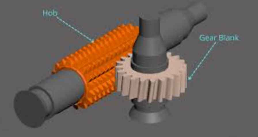
The gear hobbing process involves complex spatial motion between the rotating hob and the rotating workpiece, combined with radial and axial feeds. Multiple coordinate systems are established to describe this relationship, as shown conceptually in the figure below.
The key transformations include the hob’s rotation \(\phi\), its axial feed \(\mu(\phi)\), the workpiece rotation \(\psi(\phi)\) synchronized via the gear ratio, and the radial installation distance \(a\) which incorporates the gear’s profile shift \(x\). The surface swept by the \(k\)-th cutting edge in the workpiece coordinate system \(O_5-X_5Y_5Z_5\) is given by:
$$ G_g^k(s, \phi) = M_5^4 M_4^2 M_2^1 L_k^1(s) $$
The envelope of this family of surfaces, generated by all active cutting edges throughout the process, forms the machined tooth flank.
1.3 Parametric Model of the Theoretical Tooth Surface
The theoretical tooth surface of a standard involute spur gear with profile shift is used as the reference for error calculation. For the \(i\)-th tooth space, the surface generated by translating an involute curve along the gear axis is:
$$ F_i(\theta, w) =
\begin{bmatrix}
\pm \left[ r_b \sin(\theta – \Omega – i\cdot\Delta) – r_b \theta \cos(\theta – \Omega – i\cdot\Delta) \right] \\
r_b \cos(\theta – \Omega – i\cdot\Delta) + r_b \theta \sin(\theta – \Omega – i\cdot\Delta) \\
w \\
1
\end{bmatrix}
$$
where \(r_b\) is the base radius, \(\theta\) is the involute roll angle, \(w\) is the axial coordinate, \(\Omega\) is a fixed angular offset depending on tooth number and profile shift, and \(\Delta = 2\pi/z\). The surface normal vector \( \mathbf{n}_i(\theta, w) \) is derived from the cross product of the partial derivatives with respect to \(\theta\) and \(w\).
1.4 Simulation of the Hobbing Process and Error Assessment
The simulation discretizes the theoretical tooth surface into a grid of points \(F_i(\theta_m, w_n)\) with their associated normals. For each grid point, the minimum distance along its normal vector to the envelope surface generated by all hob cutting edges is computed. This minimum distance, signed according to the normal direction, defines the theoretical machining error \(\delta_i(\theta_m, w_n)\) at that point.
$$ \delta_i(\theta_m, w_n) = \min_{k, s, \phi} \left( \text{distance} \left( F_i(\theta_m, w_n), G_g^k(s, \phi) \right) \text{ along } \mathbf{n}_i \right) $$
Interpolating these discrete error values yields a continuous error function \(\delta_i(\theta, w)\) for the tooth surface. Profile error and lead error are obtained by analyzing slices of this function at constant \(w\) and constant \(\theta\), respectively.
2. Experimental Validation of the Simulation Model
To verify the accuracy of the proposed simulation and error evaluation model, gear hobbing experiments were conducted on two gears: one standard gear (shift coefficient x=0) and one large-modified gear (x=3). Their key parameters are listed below.
| Gear Parameter | Gear 1 (Standard) | Gear 2 (Large-Modified) |
|---|---|---|
| Module \(m_n\) (mm) | 2.5 | 2.5 |
| Profile Shift Coefficient \(x\) | 0 | 3 |
| Pressure Angle \(\alpha_n\) (°) | 20 | 20 |
| Number of Teeth \(z\) | 90 | 90 |
| Tip Diameter (mm) | 230 | 245 |
| Root Diameter (mm) | 218.75 | 233.75 |
A standard single-start, left-hand hob with 10 gullets and 65 mm outer diameter was used for machining. The hob speed was 450 rpm with an axial feed \(f\) of 1.5 mm/rev. The machined gears were measured on a coordinate measuring machine (CMM) by probing points corresponding to the simulation grid along their respective surface normals.
2.1 Comparison of Profile Error Results
The profile errors from simulation and measurement for several tooth spaces were compared. For both the standard and large-modified gears, the simulation results showed excellent agreement with the measured data in terms of both error magnitude and trend. This confirmed that the model accurately predicts the theoretical errors inherent to the gear hobbing process kinematics.
2.2 Comparison of Lead Error Results
The lead error (tooth alignment error) for selected tooth flanks also demonstrated a strong correlation between simulation and experiment. Both results exhibited the characteristic waviness induced by the intermittent axial feed of the hob. The close match further validated the fidelity of the simulation model for predicting machining errors in gear hobbing.
3. Analysis of Hobbing Errors for Large-Modified Flexsplines
Applying the validated model, a detailed analysis was performed on a typical harmonic gear flexspline. The primary geometric parameters are summarized in the following table.
| Component | Parameter | Value |
|---|---|---|
| Flexspline | Module \(m_n\) (mm) | 0.5 |
| Profile Shift Coefficient \(x\) | 3 | |
| Pressure Angle \(\alpha_n\) (°) | 20 | |
| Number of Teeth \(z\) | 200 | |
| Tip Diameter (mm) | 104 | |
| Hob (Standard) | Module (mm) | 0.5 |
| Pressure Angle (°) | 20 | |
| Number of Starts | 1 | |
| Number of Gullets \(Z_L\) | 12 | |
| Outer Diameter (mm) | 32 |
The simulation assumed a standard hob length with 73 effective cutting teeth and an axial feed \(f = 1.5\) mm/rev.
3.1 Simulation Results and Primary Error Characteristics
The simulated topological error map for the tooth surface revealed two dominant features: significant lead error with a wavy pattern across the face width, and a pronounced increase in profile error near the tooth tip region. The waviness is directly linked to the axial feed rate. The tip error, however, is attributed to a fundamental issue in gear hobbing large-modified gears with standard hobs: insufficient cutting action near the tooth tip.
3.2 Mechanism of Insufficient Cutting at the Tooth Tip
In gear hobbing a standard gear, the central cutting edges of the hob primarily form the final tooth profile. For a large-modified gear, the central cutting edges lose their dominant forming role. The tooth flanks are instead generated by cutting edges located farther from the hob’s center. If the hob is not long enough, the cutting edges responsible for the tip region may be absent or too weak, leaving the tip portion undercut or imperfectly formed. The simulation can identify the minimum hob length (in terms of required number of effective cutting teeth) to eliminate this issue. For the analyzed flexspline, the required minimum effective teeth on each side of the hob center are shown below for different diameters approaching the tip.
| Diameter (mm) | 103.544 | 103.658 | 103.772 | 103.886 | 104.0 (Tip) |
|---|---|---|---|---|---|
| Left Flank (Cutting Edge No.) | 37 | 38 | 39 | 40 | 41 |
| Right Flank (Cutting Edge No.) | -37 | -38 | -39 | -40 | -41 |
This indicates a minimum total of 83 effective cutting teeth (from -41 to +41) are needed for complete tip generation. The relationship between the required minimum number of effective teeth and the profile shift coefficient is strongly positive, as illustrated by the following functional trend derived from simulation data:
$$ N_{\text{min}} \propto f(x) \quad \text{where } f(x) \text{ increases with } x $$
3.3 Analysis and Control of Lead Error
The lead error is a direct consequence of the discrete axial feed in gear hobbing. The error is minimum at feed engagement points and maximum midway between them. Simulation results for different axial feeds (\(f\)) demonstrate its critical impact. A quantitative relationship between the maximum lead error \(\delta_{\text{lead max}}\) and the axial feed \(f\) was established through curve fitting based on simulation data, which can be generalized as:
$$ \delta_{\text{lead max}} \approx C \cdot f^n $$
where \(C\) is a constant and \(n > 1\), indicating a super-linear reduction in error with decreased feed. For the studied case, reducing \(f\) from 1.5 mm/rev to 0.5 mm/rev decreased the maximum lead error by approximately 89%.
3.4 Verification through Improved Process Simulation
Simulations incorporating the insights above confirm the improvement strategies. Using a lengthened hob (83 effective teeth) eliminates the excessive tip error. Subsequently, reducing the axial feed to 0.5 mm/rev drastically reduces both the lead error and the overall profile error magnitude. The profile errors for different tooth spaces under optimized conditions become uniformly small across the entire tooth profile.
4. Conclusion
This investigation into the gear hobbing of large-modified flexsplines for harmonic gears, through precise mathematical modeling and simulation, has yielded critical insights for improving machining accuracy. The primary conclusions are:
1. The use of standard hobs for gear hobbing gears with a high profile shift coefficient can lead to significant localized profile error near the tooth tip due to insufficient cutting action in that region, a phenomenon distinct from the general error patterns observed in standard gear hobbing.
2. Increasing the effective length of the hob is an effective countermeasure to ensure complete generation of the tooth tip. The simulation model provides a reliable method to determine the minimum required hob length for any given set of gear and hob parameters.
3. The axial feed rate is a dominant factor controlling the magnitude of lead error and overall surface topography in gear hobbing. A strong non-linear relationship exists, where reducing the feed rate results in a dramatic decrease in the maximum lead error. Process optimization should prioritize minimizing the feed rate within productivity constraints to achieve high-precision surfaces.
By integrating these findings—selecting a hob of sufficient length and employing a reduced axial feed—the theoretical machining errors in the gear hobbing of large-modified harmonic gear flexsplines can be substantially mitigated, thereby enhancing the potential for achieving the ultra-precise meshing characteristics required for high-performance harmonic drive applications.