
Cycloidal gears are the fundamental components within RV reducers, prized for their compact design, high stiffness, and excellent transmission accuracy. The primary method for their efficient, large-volume production is gear hobbing. However, the inherent multi-hole structure of cycloidal gears often leads to insufficient and uneven stiffness. During the gear hobbing process, the significant cutting forces involved can induce substantial and non-uniform elastic deformation of the workpiece. This deformation directly translates into machining errors, causing deviations in the final tooth profile. Consequently, the gear fails to meet the stringent precision requirements (typically a pitch diameter tolerance within ±3 µm), ultimately degrading the performance and service life of the RV reducer. Therefore, accurately predicting the cutting forces and the resulting workpiece deformation during the gear hobbing of cycloidal gears is of paramount importance. This research not only reveals the underlying deformation mechanisms but also provides a critical theoretical foundation for optimizing process parameters and developing effective error compensation strategies, which is essential for advancing domestic manufacturing capabilities for high-precision cycloidal gears.
Our research is structured around three core aspects: establishing precise geometrical and kinematic models for the gear hobbing process, developing and validating a finite element simulation model to predict cutting forces, and conducting a comprehensive finite element analysis of the cutting-force-induced deformation on the cycloidal gear. The objective is to elucidate the patterns of cutting force variation and the laws governing workpiece deformation under different machining stages and process parameters.
Geometrical Modeling and Feature Analysis of Cycloidal Gear Hobbing
The accurate geometrical definition of the cycloidal gear and its dedicated hob is the cornerstone for simulating the gear hobbing process. We derived the tooth profile equations based on the envelope method (planetary motion of a pin inside a base circle) and the principles of gear meshing. The profile of the cycloidal gear, which is essentially the equidistant curve of an arc-shortened epicycloid, can be mathematically represented. By establishing coordinate systems fixed to the cycloidal gear and the pin gear, and considering their relative rolling motion, the coordinates of a point on the gear tooth profile are derived through homogeneous coordinate transformations. The governing equations are as follows:
$$ \phi_2 = \frac{r_1}{r_2} \phi_1 = \frac{r_1}{r_1 + e} \phi_1 $$
$$ \gamma = \arctan\left( \frac{\sin \phi_2}{ (R_z / r_z) – \cos \phi_2 } \right) $$
$$ \begin{bmatrix} X_1 \\ Y_1 \\ 1 \end{bmatrix} = \begin{bmatrix} \cos(\phi_1+\phi_2) & -\sin(\phi_1+\phi_2) & e \sin \phi_1 \\ \sin(\phi_1+\phi_2) & \cos(\phi_1+\phi_2) & -e \cos \phi_1 \\ 0 & 0 & 1 \end{bmatrix} \begin{bmatrix} r_z \sin \gamma \\ R_z – r_z \cos \gamma \\ 1 \end{bmatrix} $$
Where $e$ is the eccentricity, $r_1$ and $r_2$ are the base circle radii of the cycloidal gear and pin gear respectively, $R_z$ is the pin distribution radius, $r_z$ is the pin radius, and $\phi_1$ is the rotational angle of the eccentricity. Using these equations with the basic parameters listed in Table 1, the precise tooth profile curve is generated for 3D modeling.
| Parameter | Symbol | Value (mm) |
|---|---|---|
| Pin Distribution Radius | $R_z$ | 82 |
| Eccentricity | $e$ | 1.5 |
| Cycloidal Gear Base Radius | $r_1$ | 38.5 |
| Pin Gear Base Radius | $r_2$ | 40 |
| Pin Radius | $r_z$ | 7 |
| Number of Teeth (Cycloidal Gear) | $Z_1$ | 39 |
The design of the dedicated hob cutter is based on the conjugate principle analogous to worm-gear pairing. The hob’s normal tooth profile is the conjugate curve of the cycloidal gear’s tooth profile. By considering the meshing relationship between a rack (representing the hob’s normal section) and the cycloidal gear, the hob profile coordinates $(X_c’, Y_c’)$ in the rack coordinate system are derived. The transformation is governed by the meshing condition, ensuring continuous point contact. Key hob structural parameters are then calculated based on the gear data and standard hob design guidelines, as summarized in Table 2.
| Parameter | Calculation Formula / Value |
|---|---|
| Tooth Height ($h_0$) | $h_0 = 2e = 3.0\text{ mm}$ |
| Normal Pitch ($p_n$) | $p_n = 2 \pi r_a / Z_1$ |
| Module ($m$) | $m = p_n / \pi \approx 4.1$ |
| Pitch Diameter ($d_0$) | $d_0 = d – 2h_0$ (d: hob outer diameter) |
| Helix Lead Angle ($\gamma_z$) | $\sin \gamma_z = m Z_0 / d_0$ ($Z_0$: number of hob starts) |
| Axial Pitch ($p_x$) | $p_x = p_n / \cos \gamma_z$ |
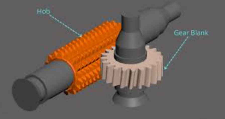
To simulate the material removal process, a precise kinematic model of the gear hobbing operation is essential. The process involves six main motions: hob rotation, workpiece rotation, and feed motions in the axial, radial, and tangential directions, plus the hob swivel angle. We established a series of coordinate systems fixed to the machine tool structure, the workpiece, and the hob. Using homogeneous transformation matrices, the spatial position of any point on a hob tooth edge relative to the workpiece at any time can be calculated. The composite transformation from the hob coordinate system ($O_6x_6y_6z_6$) to the workpiece system ($O_1x_1y_1z_1$) is given by:
$$ \mathbf{M}_{61} = \mathbf{M}_{65} \mathbf{M}_{54} \mathbf{M}_{43} \mathbf{M}_{32} \mathbf{M}_{21} $$
Where the matrices represent rotations and translations for hob rotation ($\mathbf{R}_x$), axial feed ($\mathbf{T}_z$), workpiece rotation ($\mathbf{R}_z$), etc. For a specific hob tooth $i$ on its helical line, its position is further adjusted by a phase angle $\theta_i$ and axial offset $H$. The spatial surface family $G_i^{(1)}(\phi)$ generated by this tooth edge during the synchronized motion of the hob and workpiece forms the envelope that defines the gear tooth flank.
$$ G_i^{(1)}(\phi) = \mathbf{R}_x(\phi) \cdot \mathbf{R}_z(\psi(\phi)) \cdot \mathbf{T}_z(\zeta(\phi)) \cdot \mathbf{M}_{61}^{(0)} \cdot \mathbf{r}_i^{(hi)} $$
$$ \text{with } \psi(\phi) = \pm \frac{Z_0}{Z_1} \phi, \quad \zeta(\phi) = \frac{n f_a}{2\pi} \phi $$
Here, $Z_0$ is the number of hob starts (typically 1 for finishing), $f_a$ is the axial feed per workpiece revolution, and $n$ is an integer related to the number of cuts. The Boolean subtraction of this moving surface family from the gear blank yields the transient geometry of the gear slot and, critically, the geometry of the undeformed chip. Analyzing this chip geometry is key to understanding cutting force generation. The axial feed process is divided into three stages: entry, full-depth (or complete) cutting, and exit. The chip morphology, particularly its thickness $h_i^{(hi)}$ and volume $V_i^{(hi)}$, varies significantly within a single cutting cycle in the full-depth stage as different parts of the tooth profile are generated.
Our analysis of a full cutting cycle revealed that the undeformed chip length remains relatively stable, ranging from approximately 11.5 mm to 13 mm. However, the chip thickness exhibits a pronounced variation. Cutting at the convex portions of the tooth profile (beginning and end of the cutting arc) produces thicker chips (up to ~0.35 mm), while cutting at the concave portions produces thinner chips (~0.15 mm). This variable chip thickness is a fundamental characteristic of gear hobbing that directly influences the periodic fluctuation of cutting forces.
Finite Element Simulation and Analysis of Cutting Forces in Gear Hobbing
To investigate the complex, intermittent cutting mechanics of gear hobbing, we developed a 3D finite element (FE) model. Given the cyclical and repetitive nature of the process, the model was simplified to a single-hob-tooth cutting into a single gear slot segment, dramatically reducing computational cost while preserving the essential physics. The workpiece material is 25CrMo4 steel, and its behavior under the high strain, strain-rate, and temperature conditions of machining is modeled using the Johnson-Cook constitutive law:
$$ \sigma = \left[ A + B (\epsilon)^n \right] \left[ 1 + C \ln\left(\frac{\dot{\epsilon}}{\dot{\epsilon}_0}\right) \right] \left[ 1 – \left( T^* \right)^m \right] $$
$$ T^* = \frac{T – T_{\text{room}}}{T_{\text{melt}} – T_{\text{room}}} $$
The constants for 25CrMo4 were adopted from prior high-strain-rate tests: $A=1200$ MPa, $B=891$ MPa, $C=0.02$, $n=0.2$, $m=0.64$. Material separation is governed by a critical stress-based fracture criterion. The hob is modeled as a rigid body (M35 material), and a hybrid friction model combining sticking and sliding zones is applied at the tool-chip interface. The simulation setup applied the precise kinematic constraints derived earlier, defining the rotational and feed motions of the tool relative to the fixed workpiece.
Prior to analyzing the cycloidal gear hobbing, the FE modeling approach was validated against published experimental data for hobbing of a 25CrMo steel cylindrical gear. The simulated axial and radial cutting force trends and magnitudes showed excellent agreement with experimental measurements, with a maximum error of approximately 10%, confirming the model’s reliability.
We then simulated the cutting process for different tool positions within a slot during the full-depth cutting stage, corresponding to the varying chip thicknesses. The cutting force signals, particularly the axial force ($F_z$), exhibited characteristic patterns: a rapid rise during initial engagement, a relatively stable period during steady cutting of the thick chip section, and a decline during exit. The maximum and most stable forces were observed at the tool position corresponding to the thickest chip (Position 8 in our analysis). Therefore, subsequent parameter studies focused on this condition to capture the most significant loading scenario.
A series of simulations were conducted to evaluate the influence of key gear hobbing parameters: hob cutting speed ($V_h$) and axial feed per revolution ($f_a$). The parameter ranges, informed by industry practice and the Hoffmeister formula for maximum chip thickness, are listed in Table 3.
| Parameter | Values |
|---|---|
| Hob Cutting Speed, $V_h$ (rpm) | 300, 450, 600, 750, 900 |
| Axial Feed, $f_a$ (mm/rev) | 0.25, 0.5, 0.75, 1.0 |
The simulation results, summarized in Table 4 and Figure 1, reveal clear trends. The axial feed $f_a$ has a more pronounced effect on all three force components ($F_z$: axial, $F_y$: radial, $F_x$: tangential) compared to the cutting speed $V_h$. Increasing $f_a$ directly increases the uncut chip thickness, leading to higher cutting forces. A notable threshold is observed around $f_a = 0.75$ mm/rev, beyond which force increases more steeply. In contrast, increasing $V_h$ in the studied range (with coolant) leads to a modest increase in forces, likely due to reduced material softening effects under controlled temperatures and prevailing friction mechanisms at these speeds.
| Axial Feed, $f_a$ (mm/rev) | Avg. Axial Force, $F_z$ (N) | Avg. Radial Force, $F_y$ (N) | Avg. Tangential Force, $F_x$ (N) |
|---|---|---|---|
| 0.25 | 803.4 | 324.4 | 51.0 |
| 0.50 | 811.1 | 358.1 | 52.0 |
| 0.75 | 823.5 | 408.0 | 54.7 |
| 1.00 | 914.4 | 553.5 | 82.0 |
$$ \text{Figure 1: Cutting forces increase with axial feed, showing a steeper rise beyond } f_a = 0.75 \text{ mm/rev.} $$
Finite Element Analysis of Workpiece Deformation in Gear Hobbing
The cutting forces predicted in the previous section induce elastic deformation in the cycloidal gear blank, which is structurally compromised by its lightening holes. To predict this deformation, we developed a static structural FE model. The key innovation lies in modeling the workpiece in its intermediate state at different stages of the gear hobbing process (entry, full-depth cut 1 & 2, exit), as the structural stiffness changes with material removal. The deformation is most critical in the radial ($Y$) and tangential ($X$) directions, as axial ($Z$) deformation does not directly affect the generation of the tooth profile. The gear’s rigidity is not uniform; it can be categorized into three zones based on proximity to the holes (see Figure 2): Weak-Stiffness Zone (WSZ) near trapezoidal holes, Medium-Stiffness Zone (MSZ) near circular holes, and High-Stiffness Zone (HSZ) between holes.
$$ \text{Figure 2: Stiffness zones of the cycloidal gear blank. Deformation is most severe in the WSZ.} $$
The boundary conditions replicate the actual fixturing: the central bore is constrained radially and circumferentially, the bottom face is fixed axially, and a clamping pressure is applied on the top. The cutting forces ($F_x, F_y, F_z$) from the gear hobbing simulations are applied as concentrated nodal forces on the specific, actively cut tooth flank in the model. Analyses were conducted for different cutting stages, different slot locations, and varying process parameters.
Deformation in the Weak-Stiffness Zone (WSZ): The maximum deformation consistently occurs in the WSZ, regardless of which slot is being cut. As the gear hobbing process progresses from the entry to the full-depth stage, the deformation increases, reaching a peak (e.g., ~10.47 µm) just before the exit stage begins, correlating with the maximum cutting force. When cutting different slots within the WSZ, the deformation varies slightly (10.48–11.29 µm) due to the changing local stiffness and force direction relative to the hole. Parameter studies show that axial feed $f_a$ has a dominant influence on deformation compared to cutting speed $V_h$. Increasing $f_a$ from 0.25 to 1.0 mm/rev increases max deformation from 11.03 to 12.74 µm, while increasing $V_h$ from 300 to 750 rpm increases it only from 10.69 to 11.29 µm (at $f_a=0.5$ mm/rev).
Deformation in the Medium-Stiffness Zone (MSZ): A critical finding is that even when cutting a slot in the MSZ, the maximum deformation of the entire gear still manifests in the WSZ. The local deformation around the MSZ slot itself is lower (in the range of 4–8 µm) than in the WSZ. The deformation pattern follows the same trend, peaking during the full-depth cut. This confirms that the WSZ is the most critical and vulnerable region governing the overall workpiece distortion during gear hobbing.
Radial and Circumferential Profile Error: The ultimate impact of deformation is the error in the finished tooth profile. We analyzed the radial displacement ($\Delta R$) and circumferential displacement ($\Delta L$) of nodes along a finished tooth flank in the WSZ. The radial error $\Delta R$ at a point is calculated from its coordinate shift: $\Delta R = \sqrt{X’^2 + Y’^2} – \sqrt{X^2 + Y^2}$. The circumferential error is derived from the angular shift: $\Delta L \approx R \cdot \Delta \theta$, where $\Delta \theta$ is related to the radial displacement and the nominal radius. Results show that both error components are more sensitive to axial feed $f_a$ than to cutting speed $V_h$. The maximum predicted radial deformation was 8.19 µm, and the maximum circumferential deformation was 5.67 µm, both occurring at the highest feed rate of $f_a=1.0$ mm/rev. These values are significant relative to the required gear tolerance.
| Axial Feed, $f_a$ (mm/rev) | Max. Total Deformation in WSZ (µm) | Max. Radial Profile Error, $\Delta R$ (µm) | Max. Circumferential Error, $\Delta L$ (µm) |
|---|---|---|---|
| 0.25 | 11.03 | ~6.5 | ~3.0 |
| 0.50 | 11.23 | ~7.0 | ~3.5 |
| 0.75 | 11.75 | ~7.5 | ~4.5 |
| 1.00 | 12.74 | 8.19 | 5.67 |
Conclusion and Outlook
This research systematically investigated the cutting mechanics and workpiece deformation in the gear hobbing of RV reducer cycloidal gears. The main conclusions are as follows:
1. Geometrical and Kinematic Modeling: Accurate mathematical models for the cycloidal tooth profile and the dedicated hob were established based on gearing theory. The kinematic model of the gear hobbing process successfully generates the undeformed chip geometry, revealing its variable thickness (0.15–0.35 mm) within a single cutting cycle during the full-depth stage.
2. Cutting Force Prediction: A validated 3D finite element model for gear hobbing simulation was developed. The analysis confirms that the axial feed per revolution ($f_a$) is the dominant parameter influencing cutting forces, with a noticeable nonlinear increase beyond 0.75 mm/rev. Hob cutting speed ($V_h$) in the studied wet-cutting range has a comparatively minor effect.
3. Workpiece Deformation Analysis: The structural weakness induced by lightening holes leads to significant elastic deformation during gear hobbing. The Weak-Stiffness Zone (WSZ) adjacent to trapezoidal holes is consistently the location of maximum deformation, regardless of the specific slot being cut. Deformation peaks during the full-depth cutting stage. The resulting errors on the machined tooth profile, both radial ($\Delta R$) and circumferential ($\Delta L$), are primarily governed by the axial feed. Under the tested parameters, maximum deformations of 8.19 µm (radial) and 5.67 µm (circumferential) were predicted, highlighting the necessity for compensation.
This study provides a foundational framework for predicting and analyzing distortions in complex, thin-webbed components like cycloidal gears during gear hobbing. The findings suggest that reducing the axial feed rate is an effective practical strategy for mitigating deformation. For future work, the model can be enhanced by incorporating tool wear effects, thermal deformation of the workpiece and machine tool, and multi-pass cutting strategies. Furthermore, the predicted deformation maps can be directly used to develop active or post-process compensation algorithms to achieve the ultra-high precision required for high-performance RV reducers.