
In the manufacture of automotive components, the machining of odometer drive and driven gears presents a unique challenge. These gears form a pair of crossed-axes involute helical gears with a 90° shaft angle. A critical characteristic is that the sum of their helix angles equals 90° (β₁ + β₂ = 90°), and they share the same hand of helix. To produce the drive gear, a specialized gear shaping process is employed on machines like the SB6150 semi-automatic worm milling machine. The cutter used is, essentially, a helical pinion-shaped shaper cutter whose axis is positioned at 90° to the workpiece axis. Therefore, in designing this special shaper cutter, it is conceptually placed in the position of the driven gear. The cutting process between the cutter and the workpiece must be calculated according to the meshing principles of crossed helical gears. However, the calculations for the cutter’s own cutting geometry must adhere to the formulas specific to helical shaper cutters.
This discussion revisits and expands upon a design methodology often utilized in practice: the Equivalent Gear Method for determining the normal working pressure angle, αn10, between the shaper cutter and the workpiece. While this method offers significant simplification, it is an approximate calculation. Its accuracy is exceptionally high when the sum of the normal profile shift coefficients of the cutter and workpiece (xn1 + xn0) is zero or very close to zero. However, when the absolute value of this sum is significant, the calculated αn10 deviates from the precise value. Since αn10 serves as the foundational parameter for all subsequent cutting calculations—influencing center distance, cutter tip geometry, and ultimately the generated tooth form—it is imperative to quantify this error. Through a detailed case study, this analysis compares the Equivalent Gear Method against rigorous computational techniques to assess whether the resulting errors preclude its practical application in a production environment for gear shaping.
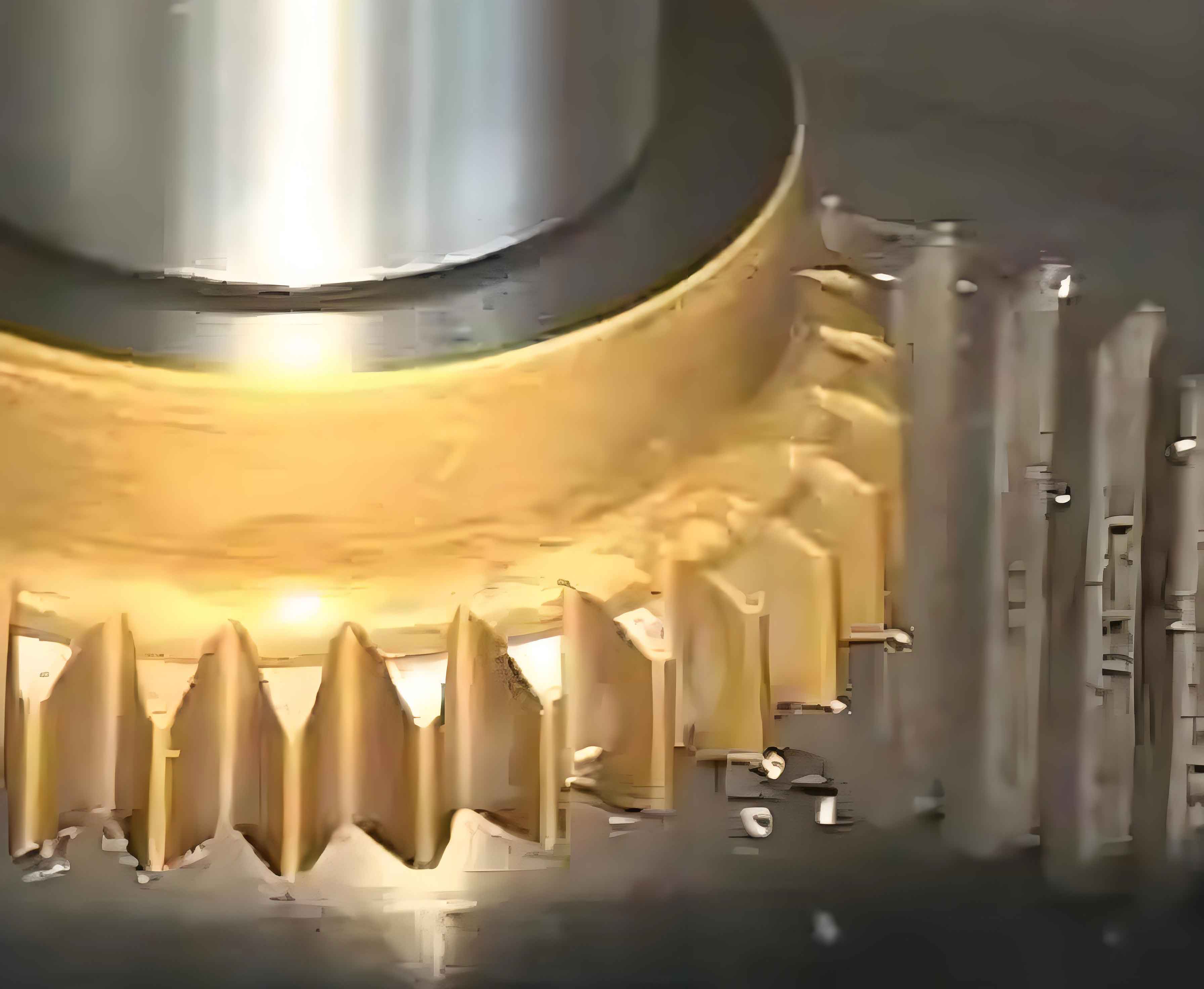
Fundamentals of the Equivalent Gear Method
The core idea of the Equivalent Gear Method is to transform the three-dimensional meshing problem of helical gears into a two-dimensional spur gear problem in the normal plane. This is achieved by using the concept of virtual (equivalent) tooth numbers. The normal working pressure angle αn10 is calculated using a formula analogous to the standard spur gear engagement equation:
$$ \text{inv} \, \alpha_{n10} = \frac{2(x_{n1} + x_{n0})}{Z_{v0} + Z_{v1}} \tan \alpha_n + \text{inv} \, \alpha_n \tag{1} $$
In this equation:
- αn is the standard normal pressure angle (e.g., 20°).
- xn1 and xn0 are the effective normal profile shift coefficients for the workpiece (gear) and shaper cutter, respectively. These must account for manufacturing tolerances and intentional tooth thinning. They are calculated as:
$$ x_{n} = \frac{S_n – \frac{\pi m_n}{2}}{2 m_n \tan \alpha_n} $$
where Sn is the actual normal circular tooth thickness at the reference diameter.
- Zv0 and Zv1 are the equivalent (virtual) tooth numbers for the shaper cutter and workpiece. Among various formulas for calculating the equivalent number, the most accurate for this purpose relates it to the transverse pressure angle:
$$ Z_{v0} = \frac{\text{inv} \, \alpha_{t0}}{\text{inv} \, \alpha_n} Z_0, \quad Z_{v1} = \frac{\text{inv} \, \alpha_{t1}}{\text{inv} \, \alpha_n} Z_1 \tag{2} $$
The transverse pressure angles αt are derived from the normal pressure angle and the helix angle β at the reference cylinder:
$$ \alpha_t = \arctan \left( \frac{\tan \alpha_n}{\cos \beta} \right) $$
Case Study: Applying the Equivalent Gear Method
To illustrate the method and its subsequent error analysis, we define a specific odometer drive gear set for gear shaping.
Workpiece (Odometer Drive Gear) Specifications:
- Normal module, mn = 1.75 mm
- Normal pressure angle, αn = 20°
- Helix angle (right-hand), β₁ = 81.3577777778°
- Number of teeth, Z₁ = 6
- Normal circular tooth thickness, Sn1 = 1.9725 mm
- Theoretical normal profile shift coefficient, xn1 (theo) = -0.5
- Tip diameter, Da1 = 71.63 mm
Driven Gear (Concepts for Cutter Design) Specifications:
- Number of teeth, Z₂ = 8
- Helix angle (right-hand), β₂ = 8.64222222°
- Theoretical normal profile shift coefficient, xn2 = +0.5
Shaper Cutter (Designed to occupy driven gear’s mesh position):
- Number of teeth, Z₀ = 57
- Helix angle, β₀ = β₂ = 8.64222222°
- Normal circular tooth thickness, Sn0 = 2.88834 mm
Step 1: Calculate Effective Profile Shift Coefficients
First, we compute the effective coefficients that include the tooth thickness specifications.
$$
x_{n1} = \frac{1.9725 – \frac{\pi \cdot 1.75}{2}}{2 \cdot 1.75 \cdot \tan 20^\circ} \approx -0.6095
$$
$$
x_{n0} = \frac{2.88834 – \frac{\pi \cdot 1.75}{2}}{2 \cdot 1.75 \cdot \tan 20^\circ} \approx +0.1095
$$
The sum is |xn1 + xn0| = |-0.6095 + 0.1095| = 0.5. For this module, this represents a significant value, suggesting a potential error when using the approximate method.
Step 2: Calculate Transverse Pressure Angles
$$
\alpha_{t1} = \arctan \left( \frac{\tan 20^\circ}{\cos 81.3577777778^\circ} \right) \approx 78.928^\circ
$$
$$
\alpha_{t0} = \arctan \left( \frac{\tan 20^\circ}{\cos 8.64222222^\circ} \right) \approx 20.170^\circ
$$
Step 3: Calculate Equivalent Tooth Numbers
$$
Z_{v1} = \frac{\text{inv}(78.928^\circ)}{\text{inv}(20^\circ)} \times 6 \quad \text{(Note: inv}(78.928^\circ) \text{ is very large)}
$$
$$
Z_{v0} = \frac{\text{inv}(20.170^\circ)}{\text{inv}(20^\circ)} \times 57
$$
For practical calculation, it is easier to compute directly using formula (1) with pre-calculated components. Using the values above, the Equivalent Gear Method yields:
$$
\text{Result: } \alpha_{n10}^{(equiv)} \approx 19.7141087^\circ
$$
$$
\text{Corresponding transverse working pressure angle for cutter: } \alpha_{t0}^{‘(equiv)} \approx 19.92202775^\circ
$$
Comparison with Alternative Calculation Methods
1. Method Using Shaving Cutter Formulas
The shaving process also involves crossed helical gear meshing. A formula derived for shaving cutter recalculations can be adapted. Let i = Z₁/Z₀ and M = inv αt1 / inv αt0. Define a constant K:
$$ K = \frac{S_{n0}}{d_0 \cos \beta_0} + \text{inv} \, \alpha_{t0} – \left( \frac{\pi}{Z_1} – \frac{S_{n1}}{d_1 \cos \beta_1} – \text{inv} \, \alpha_{t1} \right) i $$
Then, the transverse working pressure angle for the cutter is found from:
$$ \text{inv} \, \alpha_{t0}’ = \frac{K}{1 + M \cdot i} \tag{3} $$
Applying this method to our example data gives:
$$
\alpha_{t0}^{‘(shave)} \approx 19.92248923^\circ, \quad \alpha_{n10}^{(shave)} \approx 19.71456496^\circ
$$
The results from this method and the Equivalent Gear Method are nearly identical, differing only in the fifth decimal place—a discrepancy far beyond the resolution of measurement instruments and drawing specifications. This indicates that for many gear shaping applications, the Equivalent Gear Method and this adapted shaving formula provide functionally equivalent results.
2. The Exact Iterative Solution
This is a more rigorous approach directly solving the fundamental geometry of crossed-axis meshing. Let:
$$ F = \text{inv} \, \alpha_{t1} + \frac{Z_0}{Z_1} \text{inv} \, \alpha_{t0} + \frac{S_{n1} + S_{n0} – \pi m_n}{m_n Z_1} $$
The exact transverse working pressure angle on the workpiece, αt1′, is found by solving the following implicit equation through iteration (e.g., Newton-Raphson method):
$$ \text{inv} \, \alpha_{t1}’ = F – \frac{Z_0}{Z_1} \, \text{inv} \left[ \arcsin \left( \frac{\sin \alpha_{t1}’ \cos \beta_{b1}}{\cos \beta_{b0}} \right) \right] \tag{4} $$
Here, βb are the base cylinder helix angles: βb = arcsin(sin β cos αn). Once αt1′ is determined, αt0′ and αn10 can be calculated using the relationship between transverse and normal angles and the mesh condition.
Applying this exact method to our case study (starting with αt1 as an initial guess and iterating) yields:
$$
\alpha_{t1}’^{(exact)} \approx 66.97752891^\circ
$$
$$
\alpha_{n10}^{(exact)} \approx 19.91036629^\circ
$$
$$
\alpha_{t0}’^{(exact)} \approx 20.12053382^\circ
$$
3. Method Using the Backlash-Free Mesh Equation System
The most fundamental description of the meshing condition for crossed helical gears is given by the system of equations enforcing zero backlash at the operating pitch cylinders. This system is transcendental.
$$
\begin{cases}
2(x_{n1} + x_{n0}) \tan \alpha_n + Z_0(\text{inv} \, \alpha_{t0} – \text{inv} \, \alpha_{t0}’) + Z_1(\text{inv} \, \alpha_{t1} – \text{inv} \, \alpha_{t1}’) = 0 \\
\frac{\sin \alpha_{t0}’}{\sin \alpha_{t1}’} = \frac{\sin \alpha_{t0}}{\sin \alpha_{t1}}
\end{cases} \tag{5}
$$
Solving this system numerically (e.g., via software) provides the precise working angles.
$$
\text{Result: } \alpha_{t0}’^{(sys)} \approx 20.12054^\circ, \quad \alpha_{n10}^{(sys)} \approx 19.91037^\circ
$$
These results are virtually identical to those from the Exact Iterative Solution (Method 2), confirming their mutual accuracy. Methods 2 and 5 are simply different mathematical formulations of the same physical principle: the sum of the operating circular tooth thicknesses must equal the operating circular pitch.
Comprehensive Error Analysis and Discussion
The primary goal of this analysis is to understand the practical implications of the error introduced by the Equivalent Gear Method in the context of gear shaping. The summary of results for the key parameter, the cutter’s transverse working pressure angle αt0′, is as follows:
| Calculation Method | αt0′ (degrees) | Deviation from Exact (minutes of arc) |
|---|---|---|
| Equivalent Gear Method | 19.92203 | ≈ -11.9′ |
| Shaving Formula Method | 19.92249 | ≈ -11.8′ |
| Exact Iterative / Equation System | 20.12054 | 0 (Reference) |
The Equivalent Gear Method underestimates αt0′ by approximately 12 minutes of arc. To analyze the consequences, it is most instructive to consider the geometry in the transverse plane, which is the plane of actual rotation and engagement during gear shaping.
1. Core Principle: The Inviolate Base Circle
Regardless of the calculation method, the design of the shaper cutter starts from its base circle diameter, Db0 = mt0 Z₀ cos αt0, which is a fixed geometric property. In the transverse plane, the involute tooth profile is uniquely generated from this base circle. Therefore, any error in αt0′ does not imply an error in the fundamental shape of the cutter’s involute profile. The error manifests in the operating point on that fixed involute.
2. Impact on Operating Pitch Diameter and Center Distance
The operating (pitch) diameter of the cutter is given by D0′ = Db0 / cos αt0′. A smaller αt0′ results in a slightly smaller D0′.
- Exact D0′ (exact) = Db0 / cos(20.12054°)
- Approx. D0′ (equiv) = Db0 / cos(19.92203°)
For our example, the approximate method yields an operating radius that is roughly 0.06 mm smaller. Consequently, the calculated center distance for the gear shaping operation, a = (D1′ + D0′)/2, will also be slightly smaller.
3. Practical Consequences for Gear Generation
The reduced calculated center distance is the most critical outcome. In the physical gear shaping process, if the machine is set to this slightly smaller center distance, the cutter will engage slightly deeper into the workpiece blank than intended by the exact design. This has two main effects:
- Root Diameter: The finished gear’s root diameter (Df1) will be slightly larger (i.e., the root is cut deeper). For odometer and many automotive gears, root diameter tolerances are often commercial or “free” tolerances, making this minor deviation (on the order of 0.1 mm or less) usually acceptable.
- Root Fillet and Undercut: The deeper cut slightly reduces the radius of the root fillet and can marginally increase the risk of undercutting at the root. However, shaper cutter designs for gears with low tooth numbers (like Z₁=6) already incorporate generous protuberance or specific tip geometry to ensure a safe root form and adequate clearance. The small additional depth from this error often remains within the built-in safety margin.
Notably, this error tends to make the cutter design more conservative. Since many odometer drive gears use zero or negative profile shift (as in the example), the Equivalent Gear Method’s error causing a deeper cut is often preferable to an error causing a shallower cut, which could leave an uncut portion at the root.
4. Correcting the Critical Dimension: Cutter Tip Diameter
If the workpiece root diameter is critical, a simple corrective calculation can be applied to the cutter’s tip diameter (Da0) to nullify the center distance error’s effect. Instead of calculating Da0 from the approximate αn10, it can be determined directly from the exact geometry required to produce the specified workpiece root diameter Df1:
$$ D_{a0} = \frac{D_{b1}}{\cos \alpha_{t1}’} + \frac{D_{b0}}{\cos \alpha_{t0}’} – D_{f1} \tag{6} $$
In this formula, αt1}’ and αt0}’ should ideally be the exact values. However, even if the approximate αt0}’ is used in this specific formula, the resulting Da0 will ensure the tool cuts exactly to the required Df1, effectively eliminating the primary functional drawback of the Equivalent Gear Method for the gear shaping operation.
Extended Considerations for Gear Shaping Process Design
The analysis of the Equivalent Gear Method opens into broader topics relevant to designing processes for gear shaping.
Influence on Tooth Thickness and Backlash: The small error in center distance has a negligible effect on the generated tooth thickness of the workpiece. The fundamental generation process ensures conjugate action based on the cutter’s true involute. The resultant slight change in the depth of cut has a minuscule second-order effect on the final space width. Operational backlash is controlled by the machine setting and subsequent adjustments, not by this theoretical design error.
Impact on Cutter Strength and Life: A marginally smaller calculated αt0′ leads to a slightly smaller calculated pitch point on the cutter tooth. This might very slightly affect the calculated bending stress for the cutter tooth, but this effect is orders of magnitude smaller than the safety factors and wear considerations that dominate cutter life in gear shaping.
When to Use Which Method? A Decision Matrix
| Situation / Requirement | Recommended Method | Rationale |
|---|---|---|
| Routine production, generous root diameter tolerance. | Equivalent Gear Method, possibly with tip diameter correction (Eq. 6). | Simplifies calculation; error is inconsequential or beneficial. Efficient for process engineering. |
| High-precision gears, tight control over all form dimensions. | Exact Iterative (Eq. 4) or Equation System (Eq. 5) method. | Eliminates theoretical error at the source. Necessary for critical aerospace or precision transmission applications. |
| Prototype development or sensitivity analysis. | Exact methods. | Provides a definitive baseline to understand the true geometry and the magnitude of approximation errors. |
| Automated CAM programming for gear shaping. | Exact methods integrated into software. | Computational power removes the need for approximation; ensures model accuracy for simulation and path generation. |
Conclusion
The Equivalent Gear Method is a proven, pragmatic approximation for designing helical shaper cutters, particularly for applications like odometer drive gear shaping. Its inherent error in calculating the normal working pressure angle becomes significant only when the algebraic sum of the effective normal profile shift coefficients of the cutter and workpiece has a large absolute value.
The analysis reveals that this error typically results in a small underestimation of the transverse working pressure angle. The primary practical consequence is a slight reduction in the calculated gear shaping center distance, leading to a minimally deeper cut on the workpiece. In many industrial contexts, especially where the drive gear has zero or negative profile shift, this effect is either within permissible tolerances or is actually desirable as it provides a conservative margin against root interference. The method’s simplicity offers substantial advantages in engineering efficiency.
For applications demanding high precision, or when the workpiece root form is critically constrained, employing the exact iterative solution or solving the backlash-free mesh equations is essential. Furthermore, a simple corrective calculation for the cutter’s tip diameter can mitigate the primary drawback of the approximate method, enhancing its utility.
Therefore, while acknowledging its approximate nature, the Equivalent Gear Method remains a viable and widely applicable tool in the gear shaping designer’s repertoire. Its intelligent application, with an understanding of the associated errors and corrective strategies, allows for the efficient and reliable production of a vast range of helical gears, including specialized components like automotive odometer drives.