
In my experience with the development of advanced transmission systems, particularly within the demanding sectors of aerospace and high-performance machinery, the push towards miniaturization, increased precision, and enhanced reliability has become paramount. One critical pathway to achieving these goals is the adoption of internal gear assemblies utilizing gears with a low tooth count. However, the successful implementation of these assemblies is often hindered by significant challenges encountered during their manufacturing. The primary method for producing internal gears is the gear shaping process, but when applied to fewer-teeth internal gears, it frequently leads to problematic outcomes such as tooth tip undercutting, the formation of burrs on the flanks and edges, and notably reduced tool life. A thorough investigation reveals that these issues predominantly stem from various forms of interference that occur during the gear shaping cycle. Among these, interference caused by the tool relief motion—often termed “cutter reliving interference”—is a principal culprit. This article aims to delve into the mechanics of the gear shaping process for such gears, establish a method for quantifying relief interference, and propose effective strategies to mitigate these challenges, thereby enabling the production of higher-precision components and more durable cutting tools.
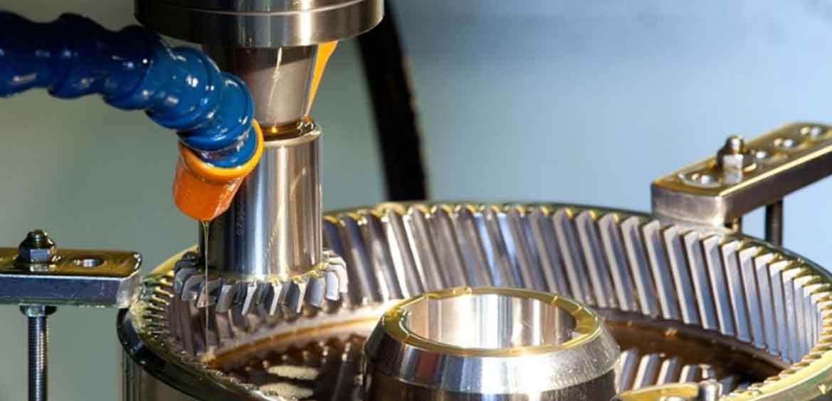
Defining the Challenge: Fewer-Teeth Internal Gears and the Shaping Process
From a practical standpoint, a fewer-teeth internal gear is typically defined as one with a tooth count below the theoretical minimum to avoid undercut when generated by a pinion-type cutter. For a standard gear with a 20-degree pressure angle, this minimum is 17 teeth. In industrial practice, however, internal gears with tooth counts below 25 are commonly classified as “fewer-teeth” due to the increased processing difficulties they present. The gear shaping cutter itself must have fewer teeth than the internal gear being cut to allow for necessary clearance. Consequently, cutters designed for 17 teeth or fewer are specifically engineered to address the unique demands of this task.
To clearly analyze the gear shaping process, it is essential to define the gear surfaces involved. Considering a setup where both the internal gear blank and the shaper cutter rotate clockwise, and the cutter performs its downstroke for cutting, we establish the following conventions: The left flank of the cutter tooth (relative to its direction of rotation) is the trailing flank, and the right is the leading flank. The side where the tool enters the cutting engagement is the roughing side or entry side, while the side where it disengages is the finishing side or exit side. Correspondingly, the right flank of the gear tooth space being generated is its leading flank, and the left is its trailing flank.
The gear shaping process for internal gears is fundamentally a generating process. The cutter and the gear blank rotate in a synchronized relationship (rolling without slipping) while the cutter reciprocates axially. Material removal occurs during the power stroke (usually the downstroke). A critical ancillary motion is the “relief” or “back-off” motion. To prevent rubbing and collision between the cutter’s non-cutting clearance faces and the newly generated gear surface, the cutter must retract radially away from the workpiece during its return stroke (upstroke). It is precisely during this relief motion that the most severe interference problems for fewer-teeth gears manifest.
Deep Dive into Relief Interference during Gear Shaping
The genesis of relief interference can be visualized at a specific instant in the gear shaping cycle. At the moment the cutter finishes a cut and begins its retraction, the relative positions of the cutter teeth and the partially formed or fully formed gear teeth create potential collision zones.
Two primary types of relief interference are identified:
- Tooth Tip Interference (Undercutting during Retraction): The outermost corner (tip) of a cutter tooth, which is not actively engaged in the primary generating action at that instant, can intersect with and gouge the tip of the corresponding internal gear tooth during the radial retraction motion. This results in a undercut gear tooth tip or a pronounced burr.
- Flank Interference (Rubbing during Retraction): The lower portion of the cutter tooth’s active profile (below the current depth of cut) can interfere with the uncut material of the gear blank or the profile generated in a previous stroke. This causes severe abrasive rubbing on the cutter flanks, leading to accelerated, non-uniform wear, and often leaves burrs on the gear’s top land and exit-side edge. This type of interference is particularly detrimental to tool life.
Mathematical Modeling for Interference Prediction
To proactively address these issues, a quantitative method for predicting relief interference is necessary. The analysis employs the law of gearing and coordinate transformation techniques. The tooth profile normal method is particularly effective for directly calculating the generated gear profile from the cutter profile.
Let us define two coordinate systems: $S_0 (O_0 – X_0, Y_0)$ attached to the gear shaping cutter, and $S_2 (O_2 – X_2, Y_2)$ attached to the internal gear workpiece. The center distance is $a_{02} = O_0O_2$, and the gear ratio $i_{02}$ is constant. The transformation from gear coordinates $(x_2, y_2)$ to fixed coordinates $(x, y)$ and then to cutter coordinates $(x_0, y_0)$ is given by:
$$
\begin{aligned}
x &= x_2 \cos \phi_2 – y_2 \sin \phi_2 \\
y &= x_2 \sin \phi_2 + y_2 \cos \phi_2 – r_2 \\
x_0 &= x \cos \phi_0 + y \sin \phi_0 + r_0 \sin \phi_0 \\
y_0 &= -x \sin \phi_0 + y \cos \phi_0 + r_0 \cos \phi_0
\end{aligned}
$$
where $r_0$ and $r_2$ are the pitch radii of the cutter and gear, and $\phi_0$ and $\phi_2$ are their rotation angles, linked by $\phi_2 = i_{02} \phi_0$.
Knowing the cutter profile $(x_0, y_0)$, the generated internal gear profile $(x_2, y_2)$ can be found by solving the inverse transformation:
$$
\begin{aligned}
x_2 &= x_0 \cos(\phi_2 – \phi_0) + y_0 \sin(\phi_2 – \phi_0) + a_{02} \sin \phi_2 \\
y_2 &= -x_0 \sin(\phi_2 – \phi_0) + y_0 \cos(\phi_2 – \phi_0) + a_{02} \cos \phi_2
\end{aligned}
\tag{1}
$$
The trochoid traced by the cutter tip (point $A$ at radius $r_A$) forms the root fillet of the gear and is given by:
$$
\begin{aligned}
x_2 &= r_A \sin(\phi_2 – \phi_0) + a_{02} \sin \phi_2 \\
y_2 &= r_A \cos(\phi_2 – \phi_0) + a_{02} \cos \phi_2
\end{aligned}
\tag{2}
$$
Calculating Relief Interference Magnitude
Type 1 (Tip Interference) Check: The condition to avoid tip gouging is that the distance from the interfering cutter tip to the line of centers must always be less than or equal to the distance from the corresponding gear tooth tip to the line of centers at every point during radial infeed. For the final depth, this simplifies to checking if $r_{a2} \sin \lambda_2 – r_{a0} \sin \lambda_0 \ge 0$, where $\lambda_0$ and $\lambda_2$ are the angles subtended by the tip radii relative to the line of centers. For intermediate depths, the gear tip circle equation $(x_2^2 + (y_2 + a_n)^2 = r_{a2}^2)$ is solved simultaneously with the transformed cutter profile equation to find the gear tip point distance $L_A$, which is then compared to the cutter tip distance $L_B = r_{a0} \sin \lambda_0$.
Type 2 (Flank Interference) Calculation: This is a more critical analysis. Consider the last cutting position (profile $E_0$) and the retracted position of the cutter after a radial relief amount $a_r$ (profile $E_{01}$). The interference width and height on the gear blank can be approximated by finding the intersection of these two cutter profiles with the gear’s outer diameter (or current cut depth circle).
The cutter profile in the cutting position is given by Eq. (1) or its explicit form in $S_0$:
$$
\begin{aligned}
x_0 &= x_c \cos(n\theta_z + \theta_f) \pm y_c \sin(n\theta_z + \theta_f) \\
y_0 &= x_c \sin(n\theta_z + \theta_f) + y_c \cos(n\theta_z + \theta_f)
\end{aligned}
\tag{3}
$$
where $(x_c, y_c)$ defines the basic cutter tooth form, $\theta_z$ is the tooth spacing angle, $\theta_f$ is the half of pitch circular tooth thickness angle, and $n$ is the tooth index.
For radial relief, the profile in the retracted position is:
$$
\begin{aligned}
x’_0 &= x_c \cos(n\theta_z + \theta_f) \pm y_c \sin(n\theta_z + \theta_f) \\
y’_0 &= x_c \sin(n\theta_z + \theta_f) + y_c \cos(n\theta_z + \theta_f) – a_r
\end{aligned}
\tag{4}
$$
The points of intersection $(F$ and $F_1)$ of profiles $E_0$ and $E_{01}$ with the gear circle of radius $R_2$ at center distance $a_n$ are found by solving the system:
$$
\begin{cases}
x_0, y_0 & \text{from (3)} \\
x’_0, y’_0 & \text{from (4)} \\
x_2^2 + (y_2 + a_n)^2 = R_2^2 & \text{(Gear Circle)} \\
\text{Coordinate transform between } S_0 \text{ and } S_2
\end{cases}
$$
The lateral interference width is approximated by $|F – F_1|$, and the vertical interference height is $|F – N|$, where $N$ is the intersection point of profiles $E_0$ and $E_{01}$.
For side relief (retraction at an angle $\theta_r$), the retracted profile equation becomes:
$$
\begin{aligned}
x’_0 &= x_c \cos(n\theta_z + \theta_f) \pm y_c \sin(n\theta_z + \theta_f) + a_r \sin \theta_r \\
y’_0 &= x_c \sin(n\theta_z + \theta_f) + y_c \cos(n\theta_z + \theta_f) – a_r \cos \theta_r
\end{aligned}
\tag{5}
$$
This system is then solved similarly. The calculated interference volume (width $\times$ height) represents material that was not removed in the previous cutting stroke and will therefore be impacted during the relief motion, causing friction and potential tool damage.
The Consequence: Friction in Gear Shaping and Its Classification
The inevitable consequence of the interferences described above is excessive and detrimental friction. While some friction between the chip, workpiece, and tool is inherent to any cutting process, the friction induced by geometric interference is abnormal and avoidable. It prematurely degrades the cutter, compromises surface finish, and generates burrs. Based on the location and cause, friction in gear shaping of internal gears can be categorized as follows:
| Friction Type | Primary Cause | Observed Symptoms | Primary Mitigation Strategy |
|---|---|---|---|
| Cutter Tip Friction | Interference with gear root fillet (trochoid) or gear tip during generation/relief. | One or more gear tooth tips are gouged. Severe localized wear on the cutter tip corner. | Reduce cutter tooth count ($z_0$) or its addendum modification coefficient ($x_0$). |
| Cutter Root Friction | Insufficient clearance between cutter dedendum and gear tip, causing intersection. | Accelerated wear on the cutter root/fillet area. Possible undercutting of the gear tooth tip. | Reduce $z_0$ or $x_0$; increase root clearance design. |
| Gear Roughing (Entry) Side Flank Friction | Relief interference between cutter’s roughing flank and uncut gear material on the entry side. | Excessive wear on the cutter’s entry-side cutting edge. Burrs on the gear’s exit-side (trailing flank) top land. | Reduce $z_0$, $x_0$, or relief amount $a_r$. Implement side relief ($\theta_r$). Optimize feed per stroke. |
| Gear Finishing (Exit) Side Flank Friction | Relief interference between cutter’s finishing flank and the freshly cut gear profile on the exit side. | Excessive wear on the cutter’s exit-side cutting edge and tip. Burrs on the gear’s entry-side (leading flank) top land and face edge. This is critically harmful as this surface sees no further finishing cuts. | Priority mitigation required. Reduce $z_0$, $x_0$, or $a_r$. Use side relief. Carefully balance parameters to avoid shifting interference from one side to the other. |
| Infeed Friction | Similar to exit-side friction but occurs specifically during the radial infeeding motion before full depth is reached. | Burrs on the gear’s entry-side flank during infeed (usually removed in final full-depth strokes). Localized wear on specific cutter teeth involved in initial entry. | Same as for exit-side flank friction. Use multiple, optimized infeeding steps. |
Comprehensive Strategies for Interference and Friction Mitigation
Based on the analysis, avoiding or minimizing interference is the key to successful gear shaping of fewer-teeth internal gears. A multi-faceted approach is necessary:
1. Optimal Cutter Design Parameters: The most direct influence comes from the cutter’s specification. Reducing the cutter tooth count ($z_0$) and/or its addendum modification coefficient ($x_0$) increases the effective clearance between the cutter and gear profiles, directly alleviating both tip and flank interference. This is often the first step in designing a cutter for a challenging application.
2. Relief Motion Optimization:
- Minimize Relief Amount ($a_r$): Use the smallest possible radial relief distance that still ensures clearance, as calculated by the interference model.
- Implement Side (Angular) Relief: If the gear shaping machine is equipped with the capability, retracting the cutter at an angle (typically $5^\circ$ to $12^\circ$) instead of purely radially can dramatically reduce flank interference on one side. However, this must be carefully analyzed using Eq. (5) as it may increase interference on the opposite flank. The relief angle $\theta_r$ and amount $a_r$ must be optimized together.
3. Process Parameter Optimization:
- Multi-Pass Cutting with Optimized Feed: For machines without side relief capability, programming multiple finishing strokes with a carefully calculated circumferential feed can help. The goal is to ensure that the interference volume predicted by the model is completely removed in the subsequent cutting stroke before the relief motion occurs again. This requires precise synchronization of rotational feed with the reciprocating cycle.
- Controlled Infeed Strategy: Using a multi-step radial infeed, rather than a single plunge to full depth, can manage the infeed friction and allow for better chip evacuation and thermal management.
4. Tooling and Surface Enhancement: While not eliminating geometric interference, using high-quality substrate materials, advanced coatings (like TiAlN, AlCrN), and super-finished cutting edges can reduce the coefficient of friction and increase abrasion resistance. This helps manage the residual friction that may be unavoidable after geometric optimization, thereby extending tool life.
5. Validation and Allowable Limits: Complete elimination of interference might not be geometrically possible for extremely low tooth counts. The goal then shifts to minimization. Practical experience suggests that for stable production, the calculated flank interference width should be maintained below $0.005\,\text{mm}$ for the roughing side and below $0.002\,\text{mm}$ for the critical finishing side. These thresholds help ensure that any remaining interaction does not cause significant burrs or rapid tool failure.
Conclusion
The gear shaping of fewer-teeth internal gears presents distinct challenges rooted in the kinematics of the process, primarily manifesting as relief interference. This interference leads directly to abnormal friction, tool wear, and part quality defects. By employing the mathematical framework of coordinate transformation and the law of gearing, it is possible to quantitatively predict the magnitude of both tip and flank interference. The derived equations, particularly for the flank interference width and height under different relief schemes (radial or side), provide a valuable tool for the design engineer. The mitigation strategy is not singular but a system encompassing cutter parameter selection (tooth count, modification), relief motion optimization (minimizing distance, employing angular relief), and cutting process control (multi-pass, optimized feed). Implementing this holistic approach based on predictive calculation rather than trial-and-error allows for the reliable production of high-precision, fewer-teeth internal gears, significantly improves the durability of the gear shaping cutters, and enhances overall manufacturing efficiency for advanced transmission systems.