
In my extensive experience as a manufacturing engineer specializing in gear production, I have consistently observed that the choice between gear hobbing and gear shaping significantly impacts both efficiency and precision in mechanical component fabrication. Gear hobbing is widely recognized for its high material removal rates and productivity, making it a staple in mass production environments. Conversely, gear shaping, while often slower, offers superior accuracy and the unique capability to machine internal gears and gears located close to shoulders or other obstructive features. This article delves into a detailed case study where gear shaping was indispensable due to part geometry constraints, and through innovative process optimization and fixture design, we achieved remarkable improvements in both throughput and quality. The core focus here is on enhancing gear shaping operations, a critical yet sometimes underappreciated aspect of gear manufacturing.
The fundamental principles of gear shaping involve a reciprocating cutter that simulates a gear meshing action to generate tooth profiles. The process can be described by the kinematic relationship between the cutter and workpiece. For a standard gear shaping operation, the basic indexing motion ensures proper tooth spacing, governed by the equation: $$ N_w = \frac{N_c \cdot \omega_c}{\omega_w} $$ where \( N_w \) is the number of teeth on the workpiece, \( N_c \) is the number of teeth on the cutter, \( \omega_c \) is the angular velocity of the cutter, and \( \omega_w \) is the angular velocity of the workpiece. The cutting speed \( V_c \) in gear shaping is a function of stroke length \( L_s \) and strokes per minute \( SPM \): $$ V_c = 2 \cdot L_s \cdot SPM $$ Optimizing these parameters is crucial for efficient gear shaping.
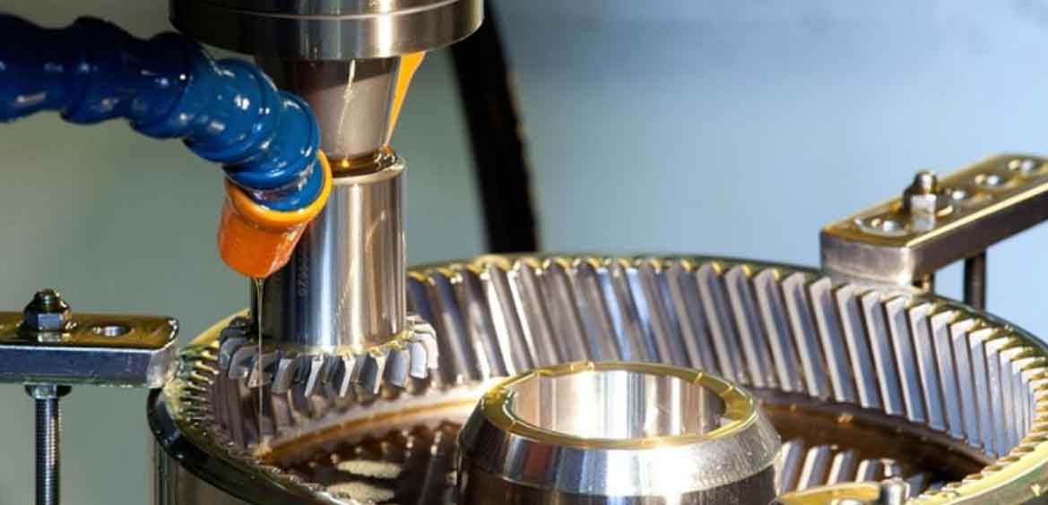
I recall a specific challenge involving a tractor power take-off drive shaft, a long axial component approximately 478 mm in length with a slender shaft diameter of 30 mm. This part featured two gears: Gear A (module 5 mm, 11 teeth) and Gear B (module 5 mm, 13 teeth). While Gear B could be readily manufactured via gear hobbing, Gear A presented a significant interference issue. The proximity of Gear B to Gear A’s location created an insufficient overtravel distance for a standard hob, rendering direct gear hobbing impossible. Consequently, gear shaping was the only viable traditional method for Gear A. However, the existing gear shaping process was fraught with inefficiencies. The setup relied on manual clamping using four bolts and plates, with positioning achieved by indicating on a ground outer diameter. This not only made the gear shaping operation labor-intensive but also extremely time-consuming, limiting output to a mere 15 pieces per shift. This bottleneck severely constrained overall production capacity and highlighted the urgent need for a comprehensive optimization of the gear shaping process.
A thorough analysis revealed two primary avenues for improvement: radical process methodology change and revolutionary fixture design. The goal was to make gear shaping faster and more reliable. The initial thought was to entirely replace gear shaping, but its unique advantages for this geometry were undeniable. Therefore, a hybrid approach was conceived. The innovation involved splitting the machining of Gear A into two distinct stages: a roughing operation using gear hobbing to remove the bulk of the material, followed by a finishing operation using gear shaping to achieve the final dimensions and accuracy. The key was to carefully calculate the hob overtravel. Through detailed CAD simulation and kinematic analysis, I determined that by reducing the final hobbed tooth depth to leave a controlled stock allowance of 1 mm on the gear tooth flanks (measurable as a reduction in chordal tooth thickness or over pin measurement), the hob could clear the interfering Gear B structure. This residual stock would then be cleanly and precisely removed by the subsequent gear shaping pass.
The theoretical foundation for this hybrid approach lies in optimizing the material removal distribution. Let \( Q_{total} \) be the total volume of material to be removed from the gear teeth. In the traditional method, gear shaping removes all of it: $$ Q_{total} = V_{shaping} $$ In the optimized method, gear hobbing removes most, and gear shaping removes the remainder: $$ Q_{total} = V_{hobbing} + V_{shaping-finish} $$ The time for each process is roughly proportional to the volume removed and the specific material removal rate (MRR) of the process. Gear hobbing typically has a much higher MRR than gear shaping. Therefore, even though two processes are used, the total time decreases dramatically because the slow gear shaping operation is only engaged for a minimal finishing cut. The stock allowance \( \delta \) for the gear shaping finish pass is critical and can be expressed in terms of the change in normal base pitch or pressure angle, but for practical purposes, controlling the span measurement or over pins distance is sufficient. For a module \( m = 5 \) mm gear, a 1 mm stock on the tooth thickness translates to a specific reduction in the span measurement \( W_k \): $$ \Delta W_k = \delta \cdot \cos(\alpha) $$ where \( \alpha \) is the pressure angle (typically 20°).
| Parameter | Traditional Process (Gear Shaping Only) | Optimized Process (Hob Rough + Shape Finish) |
|---|---|---|
| Primary Process | Gear Shaping | Gear Hobbing (Rough) |
| Secondary Process | None | Gear Shaping (Finish) |
| Stock Removal per Process | Full tooth depth (~11 mm) | Hobbing: ~10 mm; Shaping: ~1 mm |
| Estimated Machining Time | High (e.g., 12 min/part) | Low (Hobbing: 3 min; Shaping: 2 min) |
| Key Challenge | Low efficiency, manual setup | Precision control of hobbed stock |
The second major breakthrough was in fixture design for the gear shaping operation. The original manual fixture was a source of variation and consumed excessive setup time. My objective was to design an automatic, self-centering fixture that eliminated manual indication and clamping. The part used ground surfaces—an outer diameter (D) and an end face (E)—as datums. The new fixture utilizes a precision collet chuck (elastic筒夹) to clamp onto datum D. This provides a truly zero-clearance定位, ensuring high concentricity without the need for time-consuming dial indicator alignment. The actuation is integrated with the machine’s hydraulic cylinder via a system of long tension rods. This design elegantly bypasses the long, slender shaft section, keeping the fixture structure compact, lightweight, and cost-effective. The clamping force \( F_c \) is provided by the hydraulic cylinder pressure \( P \) acting on a piston area \( A_p \), transmitted through the pull rods to the collet: $$ F_c = \eta \cdot P \cdot A_p \cdot \frac{L_{lever}}{l_{lever}} $$ where \( \eta \) is the system efficiency and the lever ratio accounts for the collet’s mechanical advantage. Furthermore, the fixture incorporates a manual tooth indexing gauge. After setting the cutter position for the first workpiece using the gear shaping machine’s standard alignment procedure, this gauge allows every subsequent part to be loaded with the correct angular orientation relative to the cutter, ensuring the finishing cut removes stock uniformly from all tooth flanks. This is vital because the gear shaping finish cut is a form of generating process that requires proper phasing between the workpiece and the cutter.
The implementation of this optimized gear shaping strategy yielded transformative results. The table below quantifies the improvements:
| Metric | Before Optimization (Manual Gear Shaping) | After Optimization (Hob Rough + Auto-Fixture Gear Shape Finish) |
|---|---|---|
| Output per Shift (Gear A) | 15 pieces | 35 pieces (Gear Shaping station only) |
| Additional Output (Hobbing Roughing) | N/A | 60 pieces per shift (dedicated hobbing line) |
| Overall Effective Rate | 15 pieces/shift | 35 pieces/shift (bottleneck now at shaping) |
| Setup Time per Batch | ~25 minutes | ~5 minutes (only first-part tool setting) |
| Part Quality (Runout) | ~0.05 mm (variable) | ~0.02 mm (consistent) |
| Auxiliary Operations | Pre-grinding of location diameter C required | Pre-grinding of diameter C eliminated |
The synergy between the hybrid process and the advanced fixture is profound. The gear hobbing roughing operation not only drastically reduces the load on the gear shaping machine but also produces a very consistent pre-gear profile. This consistency in the hobbed tooth geometry, particularly in the span measurement or over pins dimension, directly facilitates the subsequent gear shaping operation. The automatic fixture ensures that every part is presented to the gear shaping cutter with identical定位, allowing the finishing cut to be optimized with aggressive yet stable parameters. For the gear shaping finish pass, I optimized the cutting parameters using a model for specific cutting force. The tangential cutting force \( F_t \) in gear shaping can be approximated by: $$ F_t = k_c \cdot a_p \cdot f_z \cdot z_c $$ where \( k_c \) is the specific cutting pressure (material-dependent), \( a_p \) is the depth of cut (now only ~0.5 mm per side), \( f_z \) is the feed per stroke, and \( z_c \) is the number of cutter teeth in engagement. With the reduced \( a_p \), we could significantly increase \( f_z \) or \( SPM \) without exceeding machine power limits or causing chatter, thus further compressing the gear shaping cycle time.
Beyond the immediate efficiency gains, this optimization had cascading benefits for the entire manufacturing sequence. The elimination of the pre-grinding operation for the location diameter C (previously needed for accurate indication) shortened the overall process flow, reduced energy consumption, and lowered tooling costs. The improved accuracy from the collet-based fixture also enhanced the quality of the gear shaping outcome. Tooth profile error, pitch error, and cumulative pitch error all showed marked improvement, which in turn benefits the performance and noise characteristics of the final assembled transmission. This case underscores a vital principle: gear shaping should not be viewed merely as a slow, last-resort process. When strategically combined with other methods and supported by intelligent tooling, gear shaping can be a pillar of efficient, high-precision manufacturing.
In conclusion, the journey to optimize the gear shaping process for this long-shaft component was a testament to systematic problem-solving and innovation. By challenging the conventional wisdom of using gear shaping in isolation, we developed a hybrid hobbing-and-shaping strategy that leveraged the strengths of both processes. The custom automatic fixture revolutionized the setup and repeatability of the gear shaping operation itself. The results—a multifold increase in productivity, enhanced part quality, and a simplified overall process—demonstrate that significant gains are possible even in mature manufacturing domains like gear shaping. This approach has since served as a template for other challenging components with similar几何 constraints. The key takeaway is that continuous optimization of gear shaping, through both process innovation and advanced tooling design, remains a fertile ground for achieving manufacturing excellence in the production of precision gear components. Future work may involve integrating in-process gauging to automatically compensate for tool wear during the gear shaping finish pass, pushing the boundaries of accuracy and autonomy even further.