
In the realm of precision mechanical component manufacturing, the production of internal profiles such as uniformly distributed polygonal internal squares (e.g., hex sockets), multiple (or single) keyways, and internal splines with missing teeth presents a significant challenge. Traditionally, these features are machined using conventional slotting machines. While functional, this method suffers from inherent limitations that compromise efficiency, consistency, and ultimate precision. My research and practical application focus on harnessing the advanced capabilities of Computer Numerical Control (CNC) gear shaping machines to overcome these limitations, establishing a superior methodology for internal profile generation.
The conventional slotting process is fraught with variables that impede high-quality production. The primary issues stem from the machine tool itself and the tooling setup. Standard slotting machines typically possess lower overall positioning accuracy and rigidity compared to modern CNC machine tools. Furthermore, the tool holder, often a simple square shank receptacle, does not guarantee precise concentricity or angular orientation of the cutting tool. Since the cutting edges of a slotting tool are rarely perfectly concentric with its mounting shank due to manufacturing constraints, the operator must manually adjust and “clock” the tool during setup. This reliance on operator skill introduces significant variability. Combined with the need to manually position the workpiece via movable tables and conduct multiple trial cuts, the process becomes time-consuming, skill-dependent, and ultimately unreliable for holding tight tolerances, especially for features like keyway symmetry and high-precision positional dimensions.
Alternative non-conventional methods like Electrical Discharge Machining (EDM) or Wire EDM also exist. However, they come with their own set of constraints. Wire EDM cannot be used for blind holes or internal features that are not accessible from the edge of the part. Processes involving electrical erosion are often strictly prohibited in critical aerospace and engine components due to concerns about surface integrity, micro-cracking, and the formation of a recast layer that may affect fatigue life. Therefore, a precise, reliable, and mechanically-based machining solution is essential.
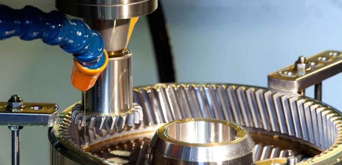
This leads to the core proposition: utilizing CNC gear shaping machines for the slotting of internal profiles. A gear shaping machine, at its fundamental level, is designed to generate precise, complex tooth forms on both internal and external gears through a reciprocating cutting motion combined with a controlled rotary indexing feed between the cutter (the shaper cutter) and the workpiece. The modern CNC variant offers exceptional control over the reciprocating stroke (Y-axis), the radial infeed (X-axis), and the precise rotational indexing of both the cutter spindle (C-axis) and/or the workpiece table (B-axis). This combination of precise linear motion and programmable rotary positioning makes it an ideal platform for executing controlled, discrete slotting operations. The goal is to adapt this high-precision kinematic chain to drive a specially designed single-point or form tool, rather than a gear shaper cutter, thereby extending the machine’s functionality beyond traditional gear manufacturing.
Technical Fundamentals and Advantages of CNC Gear Shaping for Internal Profiles
The adaptation of gear shaping technology for internal profile machining leverages several key machine characteristics. The reciprocating ram provides the primary cutting motion. Its high rigidity and guided motion ensure straightness and consistency in the cut, which is paramount for achieving good surface finish and dimensional accuracy on the side walls of a keyway or internal polygon. The CNC servo drives controlling the rotary axes provide extremely accurate angular positioning, allowing for perfect equidistant distribution of slots or polygon faces. This eliminates the cumulative error associated with manual indexing on a dividing head.
The core kinematic equation governing the relationship between cutter strokes and indexing in traditional gear shaping is adapted for discrete slotting. For a part requiring ‘N’ uniformly spaced slots, the indexing angle $ \theta_{index} $ per slot is simply:
$$ \theta_{index} = \frac{360^\circ}{N} $$
In a CNC system, this command is executed with servo-level precision, typically within a few arc-seconds, ensuring perfect uniformity. The infeed per stroke or per cycle can be precisely programmed, allowing for optimized roughing and finishing passes. The synchronized motion can be described as a function of stroke number ‘k’:
$$ Y_{position}(k) = f_{stroke}(k) $$
$$ C_{angle}(k) = n \cdot \theta_{index} \quad \text{where } n \in [0, 1, …, N-1] $$
Here, the C-axis (cutter spindle) rotates by $ \theta_{index} $ only after the complete machining of one slot, ensuring each feature is machined individually to completion before indexing.
The advantages of this approach over conventional slotting are substantial and can be summarized quantitatively:
| Performance Parameter | Conventional Slotting Machine | CNC Gear Shaping Machine Adaptation |
|---|---|---|
| Positioning Accuracy | Relies on manual scales & operator skill (±0.05 mm typical) | Governed by CNC servo resolution and ball screws (±0.005 mm or better) |
| Angular Indexing Accuracy | Manual dividing head, prone to error (±3 arc-min typical) | Direct CNC rotary axis control (±10 arc-seconds or better) |
| Process Consistency & Setup Time | High variability, lengthy setup requiring manual tool alignment and trial cuts | Minimal variability. Setup involves tool installation and program call. No trial cuts needed. |
| Keyway Symmetry Control | Difficult to guarantee, depends on tool alignment and manual measurement. | Inherently guaranteed by machine geometry and program logic. Symmetry error < 0.01 mm achievable. |
| Surface Finish (Ra) | Often limited due to tool chatter and lower rigidity (Ra 3.2 µm typical). | Superior due to high machine rigidity and controlled parameters (Ra 1.6 µm or better achievable). |
| Technology Readiness Level (TRL) | Mature but limited (TRL 6-7). | High maturity for this adapted application (TRL 8-9). |
Core Implementation: Tooling Design and Manufacturing
The success of this gear shaping adaptation hinges critically on the design and manufacture of the specialized slotting tool. Unlike a standard gear shaper cutter, this tool is designed to generate a specific internal profile, such as one face of a hexagon or the walls of a keyway.
For machining an internal hexagon via the discrete method (machining 12 adjacent faces to form a hex), a form tool with a specific included angle is required. The tool design must integrate seamlessly with the machine’s tool holding system. A common approach is to use a shank with a standard taper, such as a Morse taper, which matches the machine’s spindle. The cutting portion is ground with the precise form and necessary clearance angles.
The geometry of a form tool for creating a 120° internal corner (two faces of a hex) involves careful calculation of the rake and relief angles to ensure proper cutting and strength. The tool’s width $ W_t $ and included angle $ \alpha_t $ must be derived from the final part dimensions, accounting for tool path and potential spring. For a target internal hexagon across flats dimension $ S $ and a pilot hole diameter $ D_p $, the theoretical depth of cut $ d_{cut} $ per face is:
$$ d_{cut} = \frac{S}{2 \cos(30^\circ)} – \frac{D_p}{2} $$
The tool’s form angle is ground to $ \alpha_t = 120^\circ \pm \Delta \alpha $, where $ \Delta \alpha $ is a very tight tolerance (e.g., ±10 arc-minutes).
The major manufacturing challenges for this tool are:
- Grinding the precise form angle $ \alpha_t $ relative to the tool’s mounting datum (shank axis).
- Simultaneously achieving the necessary primary and secondary relief angles $ \gamma $ to allow cutting without excessive rubbing.
- Ensuring the cutting edge is parallel to the tool’s reference axis within a very tight tolerance (e.g., 0.01 mm) to guarantee straight, non-tapered walls.
The manufacturing sequence involves precision cylindrical grinding of the shank, followed by intricate tool and cutter grinding operations on a precision tool grinder equipped with an optical dividing head. The tool is mounted in a matched taper collet, and the dividing head is used to precisely orient the tool for grinding each relief face at the correct angle. The process requires meticulous setup and micro-level infeed control to prevent grinding burns and achieve the required edge quality.
| Tool Characteristic | Specification / Tolerance | Manufacturing Method |
|---|---|---|
| Shank Concentricity | < 0.005 mm TIR | Precision Cylindrical Grinding (between centers) |
| Form Included Angle (αt) | 120° ± 2′ | Tool & Cutter Grinding with Optical Dividing Head |
| Form Symmetry to Axis | < 0.02 mm | Tool & Cutter Grinding with precise setup alignment |
| Primary Relief Angle (γ) | 5° ± 30′ | Tool & Cutter Grinding with indexed setup |
| Cutting Edge Straightness | < 0.01 mm over length | Final precision form grinding pass |
CNC Programming Strategy for Discrete Slotting
The power of this method is unlocked through tailored CNC programming. Modern CNC gear shaping machines, often controlled by systems like Siemens Sinumerik, allow for the creation of custom cycles that orchestrate the reciprocating stroke, controlled infeed, and indexed rotation. The program logic treats each slot as an independent machining cycle.
A typical program structure for machining ‘N’ slots involves the following sequence:
- Initialization & Positioning: Calculate indexing angle $ \theta_{index} = 360/N $. Move axes to a safe start position.
- Fast Approach: Rapid movement (G00) of the Y-axis (stroke axis) to a position just above the workpiece.
- Cutting Cycle (Repeated for each slot):
- Plunge / Roughing: Execute a series of reciprocating strokes with a gradual radial infeeds (X-axis) or a stepped depth-of-cut per stroke until the full slot depth is reached. The feed per stroke $ F_{stroke} $ is critical for surface finish and tool life, calculated based on material and tool geometry: $ F_{stroke} = f_z \cdot S $, where $ f_z $ is feed per tooth (effectively per stroke for a single-point tool) and $ S $ is strokes per minute.
- Finishing Pass: A final light pass with minimal infeed and possibly a higher stroke rate to achieve final size and surface finish.
- Retract: Retract the tool clear of the slot in the Y-axis.
- Indexing: Command a precise rotary move $ \theta_{index} $ on the C-axis (or B-axis) to position the workpiece for the next slot. This is often a G91 incremental move.
- Loop Completion: Repeat steps 3-4 until ‘N’ slots are machined.
- Final Retract: Move all axes to a safe home position.
The program utilizes variables and loops for flexibility. For instance, a variable `R101` can act as a slot counter, and the loop continues while `R101 < N`. Key machining parameters like stroke length, stroke rate, infeed per cycle, and indexing angle are stored in separate control variables (e.g., `CTR[6]`, `CTR[9]`, `CTR[18]`), making the program easily adaptable to different parts. The use of synchronized motion (G64 continuous path mode) ensures smooth transitions between moves, which is beneficial for surface finish.
Practical Application and Performance Validation
The practical application of this CNC gear shaping methodology has been demonstrated on components such as input gear nuts requiring an internal hex or similar profiles. The discrete method, machining 12 adjacent faces, proves more efficient than attempting to broach a full hex form in one go, as it uses a smaller, stronger tool cutting edge, reduces cutting forces, and improves chip evacuation.
In a representative case, machining an internal hexagon on a medium-carbon steel component (hardness ~30-37 HRC) yielded the following results, starkly outperforming conventional slotting:
- Symmetry Error: Measured symmetry of opposing faces was consistently below 0.013 mm.
- Dimensional Consistency: Across-flats dimension variation was held within a 0.03 mm band across multiple parts.
- Surface Finish: Achieved surface roughness of Ra 1.6 µm or better on the side walls.
- Process Time: Total machining time was reduced by over 50% compared to the manual setup and trial-cut process on a conventional slotter.
- Elimination of Non-Value-Added Steps: The need for manual tool clocking, workpiece centering via indicator, and multiple trial cuts was completely eliminated.
The stability of the gear shaping machine’s structure, the rigidity of the tool mount, and the precision of the CNC axes combine to create a process where the final quality is primarily a function of the tool geometry and the programmed parameters, not operator skill. This makes the process predictable, repeatable, and ideal for batch production. The achieved level of accuracy in form and position is comparable to the quality levels expected from the same machine when cutting precision involute splines, demonstrating the versatility of the gear shaping platform.
Parameter Optimization and Advanced Considerations
To fully exploit this technique, optimization of key parameters is essential. This involves a balance between productivity (high material removal rate) and quality (good finish, tool life, accuracy).
Cutting Speed & Feed: The cutting speed $ V_c $ in gear shaping is determined by stroke length $ L_s $ and strokes per minute $ S_{pm} $:
$$ V_c (m/min) = \frac{2 \cdot L_s (mm) \cdot S_{pm}}{1000} $$
An optimal $ V_c $ is selected based on workpiece material. The feed per stroke $ f_z $ (mm/stroke) then determines the cross-sectional area of the chip removed. The product $ V_c \cdot f_z $ relates to the material removal rate. A conservative $ f_z $ is used for finishing to achieve good surface finish, calculated as:
$$ F_{finish} (mm/min) = f_{z,finish} \cdot S_{pm} $$
Tool Path Strategy for Finishing: To achieve the final dimension and compensate for potential tool deflection or wear, a finishing offset can be programmed. The final pass may use a slightly different tool path radius $ R_{finish} $ compared to the roughing radius $ R_{rough} $:
$$ R_{finish} = R_{rough} + \delta_{offset} $$
where $ \delta_{offset} $ is a small value (e.g., 0.02-0.05 mm) determined empirically to hit the target size.
Analysis of Symmetry Error: The potential symmetry error $ E_{sym} $ in the final part is a function of several machine and tool errors: tool form angle error $ \Delta \alpha $, tool mounting misalignment $ \beta $, and machine indexing error $ \Delta \theta $.
A simplified model for the error contribution from a single face due to angular misalignment is:
$$ E_{sym, face} \approx d_{cut} \cdot \tan(\beta) $$
This highlights why precise tool grinding and mounting are critical, as the error is magnified by the depth of the cut.
| Operation Phase | Strokes per Min (Spm) | Feed per Stroke (fz) | Infeed per Cycle / Pass | Objective |
|---|---|---|---|---|
| Roughing | 80 – 120 | 0.05 – 0.08 mm | 0.3 – 0.5 mm (radial) | High Material Removal |
| Semi-Finishing | 100 – 150 | 0.03 – 0.05 mm | 0.1 – 0.2 mm | Remove stock, prepare for finish |
| Finishing | 150 – 200 | 0.01 – 0.02 mm | 0.02 – 0.05 mm (or size offset) | Achieve final size & surface finish |
Conclusion and Broader Implications
The adaptation of CNC gear shaping technology for machining internal profiles represents a significant leap in manufacturing capability. It successfully addresses the shortcomings of conventional slotting by providing a solution that is precise, repeatable, efficient, and less dependent on operator skill. The methodology rests on three pillars: the design and manufacture of high-precision form tools, the development of intelligent CNC programs that leverage the machine’s precise kinematics, and the optimization of cutting parameters for the specific material and feature.
The results confirm that the process is not only technically feasible but also production-ready, achieving a high Technology Readiness Level (TRL 8-9). The dimensional stability, superior surface finish, and excellent geometric accuracy (symmetry, angular position) unlock the potential for using this method on high-value components where quality is non-negotiable, such as in aerospace, automotive transmission, and precision machinery. This work effectively expands the functional portfolio of the CNC gear shaping machine, transforming it from a dedicated gear production tool into a versatile, high-precision internal contour machining center. The principles outlined can be further extended to other complex internal forms, solidifying the role of advanced gear shaping technology in the modern manufacturing landscape.