
The process of gear shaping stands as a cornerstone in modern manufacturing for producing high-precision internal and external gears, splines, and complex profiles. As a critical machining operation, the reliability and accuracy of gear shaping equipment directly impact production throughput, part quality, and overall operational cost. High-performance CNC gear shaping machines, such as the model discussed here, integrate complex mechanical, electronic, and hydraulic subsystems to achieve the precise reciprocating and synchronizing motions required for generating gear teeth. Among these, the hydraulic system is paramount, responsible for critical functions including tool clamping, workpiece indexing, axis locking, and coolant supply. A failure within this system can lead to catastrophic production stoppages, costly scrap parts, and extended downtime. This article delves into a detailed case study of a persistent fault in a high-precision CNC universal gear shaping machine, systematically outlining the diagnostic methodology, root cause analysis, and solution implementation. The principles and procedures detailed herein provide a universal framework for maintenance engineers and technicians tasked with sustaining the operational integrity of advanced gear shaping and other CNC machinery.
The core principle of gear shaping involves a cutting tool, shaped like a gear, that reciprocates axially while simultaneously engaging in a synchronized rotational relationship (generating motion) with the workpiece. This process, fundamental to gear shaping, can be described by the kinematic relationship between the cutter (gear shaper) and the workpiece. The fundamental generating motion ensures the correct tooth profile is produced. The relationship is governed by the ratio of the number of teeth on the cutter ($$ z_c $$) and the workpiece ($$ z_w $$), and their rotational speeds ($$ \omega_c $$ and $$ \omega_w $$):
$$ \frac{\omega_c}{\omega_w} = \frac{z_w}{z_c} $$
During the cutting stroke, the tool removes material; on the return stroke, a relief motion (typically hydraulic) retracts the tool or workpiece to prevent drag and tool wear. The hydraulic system in such a machine is therefore not merely supportive but actively participates in the core gear shaping cycle through functions like this relief motion, tool clamping for changes between internal and external gear shaping, and providing stable pressure for various actuators.
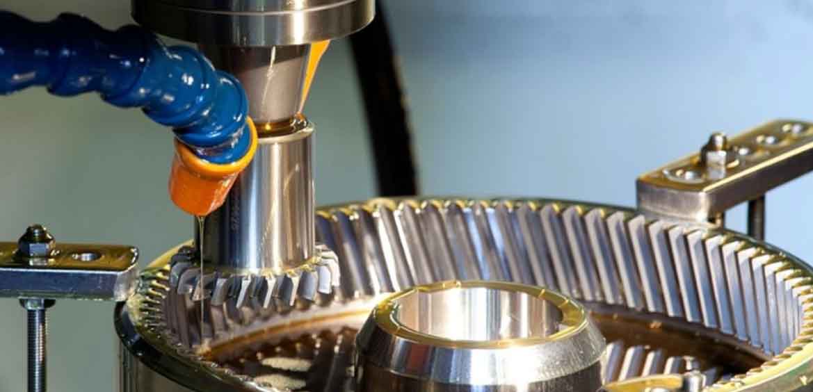
The subject of this analysis was a high-precision German-made CNC universal gear shaping machine, a vital asset for producing critical transmission components. This machine was capable of generating spur, helical, and herringbone gears, with automatic switching functionality between internal and external gear shaping operations. After approximately four hours of continuous gear shaping operation, the machine would consistently trigger a specific alarm: “F77 Fault, cam travel.” This alarm coincided with a complete and sudden halt of the entire hydraulic system. The machining process would stop abruptly. The alarm could be manually reset, and the hydraulic system restarted, allowing production to resume—only for the fault to reoccur after another similar period of operation. This intermittent yet predictable failure pattern made it impossible for the operator to ascertain the exact count of machined teeth on a workpiece at the point of stoppage, frequently leading to the scrapping of expensive, part-machined components. This recurrent issue severely disrupted production schedules and demanded a conclusive solution.
Initial diagnostics focused on the explicit alarm message related to “cam travel.” In this context, the “cam” refers to the mechanism responsible for switching the machine’s kinematic chain between internal and external gear shaping modes. This mechanism is hydraulically actuated. The first step involved inspecting the associated positional sensors (proximity switches B72.13, B72.14, B72.15) and their mechanical target. Manual and automatic cycling of the cam mechanism revealed no immediate abnormalities; the sensors responded correctly during test cycles. Monitoring these signals during an actual gear shaping run also showed stable behavior up until the moment of failure. The hydraulic pressure gauge on the main system indicated a stable pressure of 60 bar, well within the specified operating range, which initially discounted a general system pressure loss.
A deeper investigation into the machine’s Programmable Logic Controller (PLC) logic was essential. The alarm F77 was mapped to a specific PLC output, Q105.5. Tracing back the ladder logic that activated this output revealed a network of conditions. One critical input to this logic was the signal from a hydraulic pressure switch (F673) confirming that the “cam lock” mechanism was pressurized and engaged. Physically disconnecting this switch during operation did indeed trigger the F77 alarm, but significantly, it did not cause the hydraulic system to stop. This was a pivotal finding. It proved that the primary failure event was not the cam travel fault itself, but rather the concurrent shutdown of the hydraulic power unit. The F77 alarm was a consequential symptom, not the root cause. The diagnostic focus shifted from the cam mechanism to the root cause of the hydraulic system’s sudden halt.
The PLC logic controlling the main hydraulic pump motor (M27, driven by output Q52.0) was analyzed next. The logic block showed that for the pump to be disabled, a specific internal PLC flag (F131.2) had to be set. Further tracing revealed that F131.2 was controlled by a timer (T18) and another network. Crucially, the investigation led to a set of four hydraulic pressure monitoring switches (F72.21, F72.22, F72.23, F72.24), whose states were mapped to PLC inputs I23.0 through I23.3. The logic was configured such that a loss of pressure signal from any one of these switches could trigger a sequence leading to F131.2 being set and the hydraulic pump being shut down as a protective measure. A summary of the fault tree is presented in the table below:
| Observed Symptom | Primary Alarm | Key System Affected | PLC Output Triggered |
|---|---|---|---|
| Machine stops mid-cycle | F77: Cam Travel Fault | Hydraulic System & Cam Drive | Q105.5 |
| Hydraulic pump stops | Often no secondary alarm | Entire Hydraulic System | Q52.0 (De-energized) |
| Root Cause Signal | Internal PLC Flag | Monitoring Point | PLC Input |
| Loss of hydraulic pressure signal | F131.2 set via T18 | Pressure Switches F72.21-F72.24 | I23.0 – I23.3 |
With this understanding, the machine was placed in a prolonged, monitored test run without a workpiece. The status of the four critical pressure switches was logged continuously. After several hours of operation, a pattern emerged: the signal from switch F72.21 (input I23.0) began to fluctuate erratically. The indicated pressure, which should have been stable, oscillated violently between 25.5 and 31 bar. This intermittent loss of a stable “pressure good” signal was identified as the most probable cause for the protective shutdown of the hydraulic pump, which subsequently caused the cam drive to fail and trigger the F77 alarm.
To conclusively isolate the fault between the pressure switch itself and the hydraulic circuit it monitored, a component substitution test was performed. Since the four switches were identical, the physical units for F72.21 and F72.22 were swapped, while their electrical connections remained in their original positions. The test run was repeated. After a similar operational period, the erratic signal now appeared on the channel previously associated with F72.22 (now physically occupied by the original F72.21 switch). This confirmed that the fault traveled with the physical switch, not with the hydraulic line or PLC input channel. The root cause was a failing pressure sensor whose internal components degraded under prolonged operation and thermal load, leading to an unstable electrical output.
Replacing the faulty F72.21 pressure switch resolved the issue permanently. Subsequent production runs exceeding multiple shifts showed no recurrence of the F77 alarm or hydraulic system halt, restoring the gear shaping machine to full reliability and eliminating the associated scrap loss.
The methodology applied in this gear shaping machine repair offers a structured approach to troubleshooting complex CNC systems. The process can be generalized into a series of key steps, which are highly applicable to maintaining the precision required in gear shaping operations:
1. Systematic Symptom Analysis: Begin by distinguishing between the primary alarm and the fundamental system failure. In this case, separating the “cam fault” from the “hydraulic stop” was crucial. Always question the sequence of events: which failure caused the other? This involves understanding the basic dependencies in gear shaping machines, where hydraulic power enables mechanical motion.
2. Leverage All Available Information: Utilize the machine’s built-in diagnostics, PLC interface, alarm history, and parameter listings. Modern gear shaping machines provide a wealth of data. Tracing signal flow through the PLC, as demonstrated, is often the most direct path to identifying the failing component or circuit.
3. Employ Controlled Testing Methods: When direct observation is insufficient, employ methods like the substitution test used here. Other techniques include signal simulation (e.g., using a manual jumper to simulate a sensor signal) or measuring components under load with calibrated external instruments. Monitoring trends over time, especially for faults that appear after a specific duration, is essential.
4. Understand the System Interdependencies: A deep understanding of how subsystems interact is vital. In gear shaping, the relationship between the hydraulics (providing force and motion), the CNC (providing trajectory control), and the mechanical assembly (executing the cut) must be clear. For instance, the stability of the hydraulic pressure directly affects the precision of the relief motion during gear shaping, which in turn influences tool life and surface finish. The required hydraulic pressure ($$ P_{req} $$) for a clamping action can be related to the clamping force ($$ F_{clamp} $$) and piston area ($$ A_{piston} $$):
$$ P_{req} = \frac{F_{clamp}}{A_{piston}} $$
A drop in system pressure below this threshold will lead to a loss of clamping force, which can manifest as a positional fault or, worse, tool movement during gear shaping.
To prevent similar failures and ensure maximum uptime for critical gear shaping equipment, a proactive maintenance strategy is recommended. This strategy moves beyond reactive repairs to predictive and preventive measures. The following table contrasts different maintenance approaches for key subsystems involved in gear shaping:
| Subsystem | Reactive Approach | Preventive Approach | Predictive Approach |
|---|---|---|---|
| Hydraulic System | Replace components after failure (e.g., pump, valve, sensor). | Scheduled oil and filter changes; annual pressure switch calibration. | Condition monitoring of oil temperature, pressure trends, and particle count; vibration analysis on pump. |
| CNC & Drives | Replace servo drive or motor upon fault alarm. | Regular backup of parameters and PLC programs; cleaning of heat sinks and fans. | Monitoring servo load currents, following error trends, and drive temperature logs. |
| Mechanical Assembly (Gear Shaping Head) | Repair or replace worn guideways, bearings, or the tool spindle after failure. | Scheduled lubrication of guideways and gears; inspection of tool holder taper. | Periodic laser calibration of axis geometry; acoustic emission monitoring for bearing wear. |
Implementing a predictive maintenance schedule, particularly for the hydraulic system, involves logging baseline performance data during normal gear shaping cycles. Key parameters to trend include:
– Main system pressure stability over an 8-hour shift.
– Cycle time for auxiliary functions (like cam switching).
– Temperature of hydraulic reservoir.
– State of critical pressure switches and solenoid valves (logged via PLC).
Deviations from baseline trends, such as a gradual increase in the time taken to achieve lock pressure or a slow creep in operating temperature, can provide early warning of impending failures like valve wear, pump degradation, or oil contamination—all of which are detrimental to the precision of the gear shaping process.
Furthermore, maintaining the accuracy essential for high-quality gear shaping requires attention to the machine’s geometric alignment. While not directly related to the hydraulic fault, it is a critical aspect of holistic machine care. The accuracy of a generated gear tooth profile is a function of multiple axis alignments. For example, the squareness error between the vertical tool axis (Z) and the workpiece axis (C) will introduce a taper error on the gear tooth flank. Regular verification using precision artifacts and laser interferometers is recommended to ensure the machine’s capability for precision gear shaping remains intact.
In conclusion, the successful resolution of the intermittent hydraulic fault on this CNC universal gear shaping machine underscores the importance of a logical, data-driven diagnostic process. The journey from a vague operational alarm to the identification of a single failing pressure sensor highlights the interplay between mechanical, hydraulic, and electronic systems in advanced manufacturing equipment. By applying a systematic approach—analyzing symptoms, leveraging PLC logic, performing controlled tests, and understanding system dependencies—maintenance personnel can effectively restore and maintain complex machinery. The transition from reactive troubleshooting to a proactive, condition-based maintenance regimen, as outlined, is the key to maximizing productivity, ensuring part quality, and safeguarding valuable capital equipment like high-precision gear shaping machines. The principles detailed in this analysis are universally applicable, providing a robust framework for sustaining the performance and reliability of sophisticated industrial assets in an era where precision gear shaping continues to be indispensable for advanced power transmission solutions.