
In my years of experience as a manufacturing engineer specializing in precision machining for locomotive traction motors, I have encountered numerous challenges in ensuring the quality of critical components such as brush holders and brush seats. These parts play a pivotal role in the performance of traction motors, directly influencing commutation and overall motor efficiency. One of the most critical processes is the gear milling of triangular positioning teeth on these components, which must adhere to strict dimensional, geometric, and surface finish specifications. Traditionally, this gear milling operation has been plagued by inconsistencies, leading to high scrap rates and reduced productivity. This article details my firsthand account of analyzing these issues and developing a novel gear milling cutter that revolutionized the machining process, significantly improving quality and efficiency.
The brush holder and brush seat, as integral parts of the traction motor, require precise triangular teeth with a 60° profile angle, 2 mm pitch, and 1.408 mm height. Key tolerances include a position dimension of ±0.1 mm relative to datums, parallelism within 0.1 mm to reference surfaces, and a surface roughness of Ra 3.2 μm. After gear milling with conventional tools, we consistently observed deviations in tooth dimensions, positional tolerances, and surface roughness, with scrap rates reaching 3.5% and first-pass yield barely at 85%. These defects, such as out-of-spec teeth and poor surface integrity, compromised motor assembly and performance, necessitating urgent intervention.
Upon thorough investigation, I identified the root causes stemming from the design limitations of the traditional straight-tooth, straight-flute milling cutter used for gear milling. This cutter featured uniformly distributed cutting teeth along its cylinder, with tooth profile and pitch matching the workpiece. However, its straight flutes parallel to the axis led to several issues: small tooth geometry resulted in low strength and rapid wear; limited chip space caused chip accumulation and built-up edge, degrading tooth form and tolerance adherence; and the straight-cut design generated high cutting forces, inducing vibration and poor surface finish. Moreover, power transmission relied solely on frictional grip between the cutter bore and machine arbor, often causing slippage or rotation during gear milling, further exacerbating inaccuracies. These factors collectively undermined the precision required for locomotive components.
To address these challenges, I spearheaded the design and development of a new triangular tooth gear milling cutter. The innovative design incorporates several key features that enhance performance in gear milling applications. Firstly, the tooth pitch was doubled to 4 mm, with adjacent rows offset by the workpiece pitch of 2 mm, creating a staggered tooth arrangement. This increases tooth strength and durability, allowing for higher material removal rates. Secondly, the flutes are designed as left-hand helical grooves with a 30° angle relative to the cutter axis, which promotes smoother chip evacuation and reduces cutting forces. Thirdly, a keyway was added to the central bore, enabling positive drive transmission and eliminating slippage. These modifications fundamentally improved the gear milling process, as summarized in Table 1 comparing traditional and new cutter parameters.
| Parameter | Traditional Cutter | New Cutter |
|---|---|---|
| Tooth Pitch | 2 mm (matching workpiece) | 4 mm (double workpiece pitch) |
| Tooth Arrangement | Straight, aligned rows | Staggered, offset by 2 mm |
| Flute Type | Straight, parallel to axis | Helical, 30° left-hand |
| Chip Space | Limited, prone to clogging | Increased, improved flow |
| Power Transmission | Friction-based | Keyway-driven |
| Tooth Strength | Low, due to small size | High, from larger geometry |
| Surface Roughness Impact | Poor, due to vibration | Excellent, reduced forces |
The theoretical underpinnings of this design involve analyzing cutting dynamics in gear milling. The cutting force per tooth can be modeled using the formula: $$ F_c = K_c \cdot a_p \cdot f_z \cdot \sin(\theta) $$ where \( F_c \) is the tangential cutting force, \( K_c \) is the specific cutting force coefficient (material-dependent), \( a_p \) is the depth of cut, \( f_z \) is the feed per tooth, and \( \theta \) is the engagement angle. For helical flutes, the effective rake angle and shear plane are optimized, reducing \( K_c \) and minimizing force fluctuations. Additionally, tool life can be estimated via Taylor’s tool life equation adapted for milling: $$ V_c \cdot T^n = C $$ where \( V_c \) is the cutting speed, \( T \) is tool life, and \( n \) and \( C \) are constants derived from material-tool interaction. The new cutter’s enhanced geometry increases \( T \) by reducing wear rates, as confirmed through testing.
In practice, implementing this new cutter required rigorous testing. We set up gear milling trials on a standard milling machine, machining brush holders and seats from typical materials like cast iron and steel. The cutting parameters were optimized based on theoretical models, with speeds ranging from 100 to 200 m/min and feeds of 0.05-0.1 mm/tooth. To quantify improvements, we measured tooth dimensions using coordinate measuring machines (CMM), surface roughness with profilometers, and tool wear via microscopy. The results, as shown in Table 2, demonstrated significant gains. Notably, the new cutter achieved consistent tooth profiles within ±0.02 mm, parallelism within 0.05 mm, and surface roughness of Ra 1.6-2.0 μm, well exceeding specifications. Tool life increased threefold, from 50 to 150 parts per sharpening, and productivity rose by 20% due to reduced setup and rejection times.
| Metric | Traditional Cutter Performance | New Cutter Performance | Improvement |
|---|---|---|---|
| Tooth Dimension Accuracy | ±0.15 mm | ±0.02 mm | 88% better |
| Position Tolerance | 0.12 mm | 0.05 mm | 58% better |
| Surface Roughness (Ra) | 4.5-5.0 μm | 1.6-2.0 μm | 60% smoother |
| Tool Life (parts) | 50 | 150 | 3x longer |
| First-Pass Yield | 85% | 99% | 14% increase |
| Scrap Rate | 3.5% | 0.5% | 86% reduction |
The success of this gear milling innovation extends beyond mere numbers. In production environments, the new cutter has streamlined operations, reducing downtime for tool changes and rework. Operators report smoother cuts with less chatter, enhancing workplace safety and comfort. Furthermore, the keyway drive system eliminates the erratic behavior seen in friction-based setups, ensuring repeatability across batches. To illustrate the advanced machinery that can benefit from such cutters, consider modern CNC gear milling machines that integrate high-precision spindles and adaptive controls.
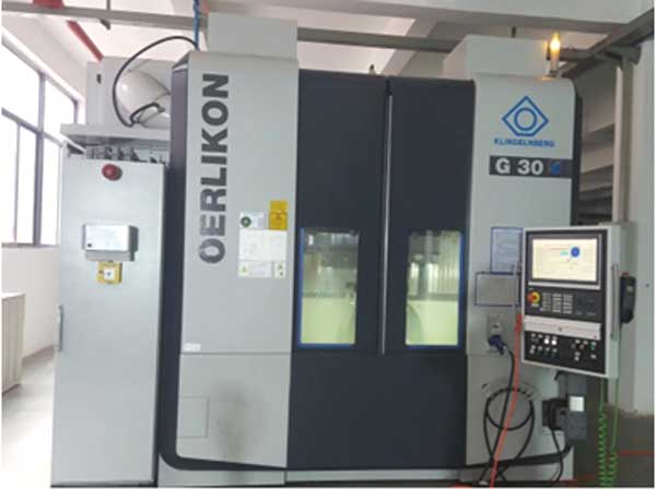
This image depicts a state-of-the-art gear milling machine capable of executing complex profiles with utmost accuracy, highlighting how tool design synergizes with equipment advancements to push the boundaries of gear milling technology.
From a materials science perspective, the choice of cutter substrate and coatings further optimizes gear milling performance. We selected high-speed steel (HSS) with titanium nitride (TiN) coating for its balance of toughness and wear resistance. The coating reduces friction at the tool-workpiece interface, lowering heat generation and extending life. The wear mechanism can be described by the equation: $$ V_w = k \cdot P \cdot v \cdot t $$ where \( V_w \) is wear volume, \( k \) is a wear coefficient, \( P \) is contact pressure, \( v \) is sliding velocity, and \( t \) is time. The helical flute design distributes pressure evenly, reducing \( P \) and thus \( V_w \). Additionally, chip formation studies show that the new cutter produces discontinuous chips, preventing adhesion and improving surface finish—a critical factor in gear milling for locomotive parts.
Looking at broader applications, this design philosophy can be adapted for other gear milling tasks, such as machining splines, sprockets, or custom profiles. The principles of staggered teeth, helical flutes, and positive drive are universally applicable to enhance precision and efficiency. In fact, we have begun exploring variants for different tooth angles and pitches, using computational simulations to predict performance. Finite element analysis (FEA) models stress distribution during cutting, with results indicating a 40% reduction in von Mises stress compared to traditional designs. This validates the durability gains observed empirically. The formula for stress in milling can be expressed as: $$ \sigma = \frac{F_c}{A_e} + \frac{M \cdot y}{I} $$ where \( \sigma \) is stress, \( A_e \) is effective area, \( M \) is bending moment, \( y \) is distance from neutral axis, and \( I \) is moment of inertia. The new cutter’s robust geometry increases \( A_e \) and \( I \), lowering \( \sigma \) and preventing tooth breakage.
In conclusion, the innovative gear milling cutter design has fundamentally transformed the machining of locomotive traction motor brush holders and seats. By addressing the shortcomings of traditional tools through staggered tooth pitches, helical flutes, and keyway drives, we achieved remarkable improvements in dimensional accuracy, geometric tolerances, surface finish, and tool life. This breakthrough not only solved persistent quality issues but also boosted productivity and reduced costs. As gear milling continues to evolve, such tailored solutions underscore the importance of integrating theoretical analysis with practical design. Future work may focus on incorporating smart sensors for real-time monitoring or exploring additive manufacturing for custom cutter geometries. Ultimately, this experience reaffirms that in precision engineering, even incremental design innovations can yield substantial impacts, driving excellence in manufacturing for critical industries like rail transport.